11.13.2.3
Testing the gas medium supervision for temperature alarm and
temperature lockout conditions
GUID-189AF20B-D0E3-453D-A787-68F25D0903D3 v2
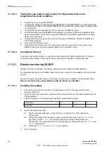
1.
Activate the binary input SENTEMPQ.
2.
Consider the analogue temperature input SENTEMP and set SENTEMP to a value higher than
TempAlarmLimit
, check that outputs TEMPALM and ALARM are activated after a set time delay
of
tTempAlarm
.
3.
Temperature lockout input SETTLO can be used to set TEMPLO signal.
4.
Ensure that binary input SENTEMPQ is activated and increase further the temperature input
above
TempLOLimit
, check that the outputs TEMPLO and LOCKOUT appear after a set time
delay of
tTempLockOut
.
5.
Activate BLOCK binary input and check that the outputs TEMPALM, TEMPLO, ALARM and
LOCKOUT disappear.
6.
Reset the BLOCK binary input.
7.
Ensure that temperature lockout condition exists and then activate the reset lockout input
RESETLO and check that the outputs TEMPLO and LOCKOUT reset.
11.13.2.4
Completing the test
GUID-1A0D8AF0-4C48-45E8-B31D-96734ED1A4D2 v2
Continue to test another function or end the test by changing the
TestMode
setting to
Off
. Restore
connections and settings to their original values, if they were changed for testing purposes.
11.13.3
Breaker monitoring SSCBR
GUID-10D26C82-79FF-4EAD-AE4A-2F2DBE965087 v3
Prepare the IED for verification of settings outlined in section “Testing the IED operation”.
The Signal Monitoring tool in PCM600 shows the service values that are available on the Local HMI
as well.
Values of the logical signals belong to the breaker monitoring are available on the local HMI under:
Main menu/Test/Function status/Monitoring/BreakerMonitoring /SSCBR:x
11.13.3.1
Verifying the settings
GUID-962A344D-5F8D-49A6-B3AC-29C7FEED0A3D v4
1.
Connect the test set for the injection of a three-phase current to the appropriate current
terminals of the IED.
2.
If current need to be injected for a particular test, it should be done in the phase selected by the
PhSel
parameter.
3.
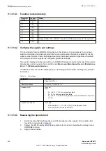
Follow the sequence for positioning the auxiliary contacts before testing:
POSCLOSE
0
1
0
POSOPEN
0
0
1
4.
Test of CB contact travel time
4.1. Test the set timing defined by
OpenTimeCorr
,
CloseTimeCorr
,
tTrOpenAlm
and
tTrCloseAlm
.
4.2. Change the status of the auxiliary contacts such that travel time to open
TTRVOP
and
travel time to close
TTRVCL
exceed the respective set values (
tTrOpenAlm
and
tTrCloseAlm
). The measured travel time for opening and closing is shown on
TTRVOP
and
TTRVCL
respectively.
4.3. Check that
TRVTOPAL
and
TRVTCLAL
are activated.
5.
Test of CB status
Section 11
1MRK 511 403-UEN Rev. L
Testing functionality by secondary injection
192
Bay control REC670
Commissioning manual
© 2017 - 2022 Hitachi Energy. All rights reserved
Summary of Contents for REC670
Page 1: ...Relion 670 SERIES Bay control REC670 Version 2 2 IEC Commissioning manual ...
Page 2: ......
Page 28: ...22 ...
Page 54: ...48 ...
Page 60: ...54 ...
Page 66: ...60 ...
Page 90: ...84 ...
Page 212: ...206 ...
Page 218: ...212 ...
Page 232: ...226 ...
Page 240: ...234 ...
Page 241: ...235 ...


