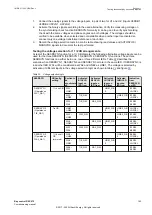
Step No.
OpMode
Changes after step 2
Expected output
3-a
Instantaneous 1
cycle or
Instantaneous 2
cycle
Change UL1 to 20V
STL1 , STLOW, START signal should be
TRUE for 100 ms
3-b
Instantaneous 1
cycle or
Instantaneous 2
cycle
Change UL1 back to 63.5V
STL1 , STRISE, START signal should be
TRUE for 100 ms
3-a
RMS or DFT Mag
Change UL1 to 20V
STL1, STLOW, START signal should be
TRUE for 100 ms
3-b
RMS or DFT Mag
Change UL1 back to 63.5V
STL1 , STRISE, START signal should be
TRUE for 100 ms
3-a
DFT Angle (vector
shift)
Change UL1 to 63.5V at
15° without changing
frequency
STL1, START signal will be TRUE for 100
ms.
3-b
DFT Angle (Vector
shift)
Change UL1 to 63.5V at 0°
without changing frequency
STL1, START signal will be TRUE for 100
ms
4.
Repeat Step
with UL2 changes for different mode.
11.9.4.2
Completing the test
GUID-2FE5E5F0-0E6C-499E-93D2-471C183B89BF v2
Continue to test another function or end the test by changing the
TestMode
setting to
Off
. Restore
connections and settings to their original values, if they were changed for testing purposes.
11.9.5
Current based delta supervision DELISPVC
GUID-9EAEFF02-62C2-4FA7-8F3D-E92391206F7F v2
Prepare the IED for verification of settings outlined in Section
"Preparing the IED to verify settings"
11.9.5.1
Verifying the signals and settings
GUID-86324E4D-E054-495F-9D64-29741FBD8CBE v2
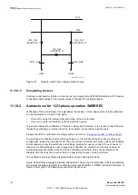
Make sure that the function is connected to SMAI function with I3P signal.
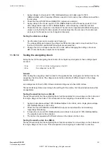
Delta supervision function has four different modes of operation. Proceed as follows to test the
function in a particular mode.
1.
Set the following parameters:
•
Operation
= ON
•
MeasMode
= Phase-to-ground
•
Imin
= 10% of
IBase
•
DelI>
= 80% of
IBase
•
DeltaT
= 2
•
tHold
= 100
2.
Set the constant current input of IL1 = 1A at 0° and IL2 = 1A at 120° and IL3 at -120°
secondary at rated frequency.
3.
Based on the mode of operation, carry out the following changes on input condition of Step
to
detect start condition.
Each mode is given for increase and decrease operation. (3-a and 3-b)
1MRK 511 403-UEN Rev. L
Section 11
Testing functionality by secondary injection
Bay control REC670
155
Commissioning manual
© 2017 - 2022 Hitachi Energy. All rights reserved
Summary of Contents for REC670
Page 1: ...Relion 670 SERIES Bay control REC670 Version 2 2 IEC Commissioning manual ...
Page 2: ......
Page 28: ...22 ...
Page 54: ...48 ...
Page 60: ...54 ...
Page 66: ...60 ...
Page 90: ...84 ...
Page 212: ...206 ...
Page 218: ...212 ...
Page 232: ...226 ...
Page 240: ...234 ...
Page 241: ...235 ...


