background image

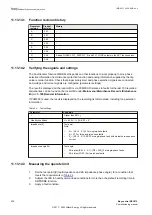
IEC13000252-1-en.vsd

7.

Manually execute Raise commands to step up the tap changer one step for all transformers in
the parallel group

8.

Check that the value of 

BUSVOLT

 is below overvoltage blocking level 

OVPartBK

 and above the

undervoltage blocking level 

UVPartBK

.

9.

Set the control mode to 

Auto

 for each transformer in the parallel control group

The Master in the parallel group will issue a Lower command after time delay t1, which will also
be repeated by the Follower transformers in the group.

10.

Set Transformer 2 to Master of the parallel group and T1 to Follower (in that order) and repeat
steps 7 to 10. Undertake this same test by setting each Transformer in turn to Master

11.

Note that voltage regulation will be mutually blocked if no transformer is set to Master in the
parallel group. To confirm this function, set T1 as Master and the other transformers in the
parallel grouper set as Follower. Without allocating a new Master, set T1 to Follower and note
the 

Automatic

 block state on the local HMI for all parallel transformers

12.

Restore T1 to Master of the parallel transformer group and ensure that control mode for each
transformer is 

Automatic

.

12.1.5 

Completing the test

SEMOD176327-287 v3

After the test is completed and relevant disturbance records are saved to document the test, go to

Main menu /Clear 

on the local HMI and clear all LEDs, the process eventlist and disturbances from

the IED.

1MRK 511 403-UEN Rev. L

Section 12

Primary injection testing

Bay control REC670

211

Commissioning manual

© 2017 - 2022 Hitachi Energy. All rights reserved

Summary of Contents for REC670

Page 1: ...Relion 670 SERIES Bay control REC670 Version 2 2 IEC Commissioning manual ...

Page 2: ......

Page 3: ...Document ID 1MRK 511 403 UEN Issued July 2022 Revision L Product version 2 2 2017 2022 Hitachi Energy All rights reserved ...

Page 4: ...is product includes software developed by the OpenSSL Project for use in the OpenSSL Toolkit https www openssl org This product includes cryptographic software written developed by Eric Young eay cryptsoft com and Tim Hudson tjh cryptsoft com Trademarks ABB is a registered trademark of ABB Asea Brown Boveri Ltd Manufactured by for a Hitachi Energy company All other brand or product names mentioned...

Page 5: ...lure would create a risk for harm to property or persons including but not limited to personal injuries or death shall be the sole responsibility of the person or entity applying the equipment and those so responsible are hereby requested to ensure that all measures are taken to exclude or mitigate such risks This document has been carefully checked by Hitachi Energy but deviations cannot be compl...

Page 6: ...cerning electrical equipment for use within specified voltage limits Low voltage directive 2006 95 EC This conformity is the result of tests conducted by Hitachi Energy in accordance with the product standard EN 60255 26 for the EMC directive and with the product standards EN 60255 1 and EN 60255 27 for the low voltage directive The product is designed in accordance with the international standard...

Page 7: ... 33 3 5 Basic IED functions 37 Section 4 Starting up 39 4 1 Factory and site acceptance testing 39 4 2 Commissioning checklist 39 4 3 Checking the power supply 39 4 4 Energizing the IED 40 4 4 1 Checking the IED operation 40 4 4 2 IED start up sequence 40 4 5 Setting up communication between PCM600 and the IED 41 4 5 1 When IED has blank front panel 41 4 5 2 When IED has front port with RJ 45 41 4...

Page 8: ... 1 Overview 59 8 2 Setting the station communication 59 8 3 Verifying the communication 59 Section 9 Establishing connection and verifying the IEEE C37 118 1344 communication 61 9 1 Overview 61 9 2 Setting the PMU station communication PMU Report 61 9 3 Setting the PMU station communication PMU configuration 61 9 4 Setting the TCP UDP client communication 62 9 5 Verifying the communication 65 9 5 ...

Page 9: ...2 Completing the test 87 11 4 Current protection 87 11 4 1 Instantaneous phase overcurrent protection 3 phase output PHPIOC 87 11 4 1 1 Measuring the operate limit of set values 87 11 4 1 2 Completing the test 88 11 4 2 Directional phase overcurrent protection four steps OC4PTOC 88 11 4 2 1 Function revision history 88 11 4 2 2 Verifying the settings 88 11 4 2 3 Completing the test 89 11 4 3 Insta...

Page 10: ...eased when STALARM is reset 103 11 4 9 13 Test of FollowStart Mode behaviour 103 11 4 9 14 Test of FollowStart behaviour 103 11 4 9 15 Completing the test 103 11 4 10 Stub protection STBPTOC 104 11 4 10 1 Function revision history 104 11 4 10 2 Measuring the operate limit of set values 104 11 4 10 3 Completing the test 104 11 4 11 Overcurrent protection with binary release BRPTOC 105 11 4 11 1 Fun...

Page 11: ...ential trip and alarm levels 126 11 5 4 4 Check of trip and trip reset timers 127 11 5 4 5 Final adjustment of compensation for VT ratio differences 128 11 5 4 6 Completing the test 128 11 5 5 Loss of voltage check LOVPTUV 128 11 5 5 1 Measuring the operate limit of set values 128 11 5 5 2 Completing the test 129 11 6 Unbalance protection 129 11 6 1 Shunt capacitor cascading failure protection SCC...

Page 12: ...ailure supervision FUFSPVC 150 11 9 2 1 Checking that the binary inputs and outputs operate as expected 150 11 9 2 2 Measuring the operate value for the negative sequence function 151 11 9 2 3 Measuring the operate value for the zero sequence function 152 11 9 2 4 Measuring the operate value for the dead line detection function 152 11 9 2 5 Checking the operation of the du dt and di dt based funct...

Page 13: ... 10 6 Single command 16 signals SINGLECMD 177 11 10 7 Interlocking 177 11 11 Scheme communication 178 11 11 1 Scheme communication logic for distance or overcurrent protection ZCPSCH 178 11 11 1 1 Function revision history 178 11 11 1 2 Testing permissive underreaching 178 11 11 1 3 Testing permissive overreaching 179 11 11 1 4 Testing blocking scheme 179 11 11 1 5 Testing delta blocking scheme 17...

Page 14: ...ng the liquid medium supervision for level alarm and level lockout conditions 191 11 13 2 3 Testing the gas medium supervision for temperature alarm and temperature lockout conditions 192 11 13 2 4 Completing the test 192 11 13 3 Breaker monitoring SSCBR 192 11 13 3 1 Verifying the settings 192 11 13 3 2 Completing the test 193 11 13 4 Event function EVENT 194 11 13 5 Limit counter L4UFCNT 194 11 ...

Page 15: ...andling SETGRPS 204 11 17 1 1 Verifying the settings 204 11 17 1 2 Completing the test 204 11 18 Exit test mode 205 Section 12 Primary injection testing 207 12 1 Transformer Voltage Control ATCC 207 12 1 1 Load drop compensation function LDC 207 12 1 2 Voltage control of Parallel Transformers 208 12 1 3 Minimum Circulating Current MCC method 209 12 1 4 Master Follower MF method 210 12 1 5 Completi...

Page 16: ...7 14 2 Fault tracing 218 14 2 1 Internal fault indications 218 14 2 2 Using front connected PC 219 14 2 3 Diagnosing the IED status via the LHMI hint menu 220 14 2 4 Hardware re configuration 223 14 3 Repair instruction 224 14 4 Repair support 225 14 5 Maintenance 225 Section 15 Glossary 227 Table of contents 1MRK 511 403 UEN Rev L 10 Bay control REC670 Commissioning manual 2017 2022 Hitachi Energ...

Page 17: ...organized in the chronological order in which the IED should be commissioned The relevant procedures may be followed also during the service and maintenance activities 1 2 Intended audience GUID C9B8127F 5748 4BEA 9E4F CC762FE28A3A v11 This manual addresses the personnel responsible for commissioning maintenance and taking the IED in and out of normal service The commissioning personnel must have ...

Page 18: ...ctrical installation The chapters are organized in the chronological order in which the IED should be installed The commissioning manual contains instructions on how to commission the IED The manual can also be used by system engineers and maintenance personnel for assistance during the testing phase The manual provides procedures for the checking of external circuitry and energizing the IED param...

Page 19: ...d commissioning phase and during normal service 1 3 2 Document revision history GUID 34B323E4 1319 4D42 80CE 29B0F2D36E2C v7 Document revision Date Product version History 2017 05 2 2 0 First release for product version 2 2 A 2017 10 2 2 1 Ethernet ports with RJ45 connector added enhancements updates made to ZMFPDIS and ZMFCPDIS B 2018 03 2 2 1 Document enhancements and corrections C 2018 06 2 2 2...

Page 20: ...11 396 UEN Point list manual DNP3 1MRK 511 397 UUS Accessories guide 1MRK 514 012 BEN Cyber security deployment guideline 1MRK 511 399 UEN Connection and Installation components 1MRK 513 003 BEN Test system COMBITEST 1MRK 512 001 BEN Application guide Communication set up 1MRK 505 382 UEN User guide RIA600 1MRK 511 619 UEN 1 4 Document symbols and conventions 1 4 1 Symbols GUID 2945B229 DAB0 4F15 ...

Page 21: ...messages are shown in Courier font For example to save the changes in non volatile memory select Yes and press Parameter names are shown in italics For example the function can be enabled and disabled with the Operation setting Each function block symbol shows the available input output signal the character in front of an input output signal name indicates that the signal name may be customized us...

Page 22: ... GF2PTUV GF2PVOC PH1PTRC GF2MMXN GF2PHAR GF2PTOV GF2PTUC GF2PTUV GF2PVOC PH1PTRC CVMMXN CVMMXN CVMMXN DPGAPC DPGGIO DPGAPC DRPRDRE DRPRDRE DRPRDRE ECPSCH ECPSCH ECPSCH ECRWPSCH ECRWPSCH ECRWPSCH EF4PTOC EF4LLN0 EF4PTRC EF4RDIR GEN4PHAR PH1PTOC EF4PTRC EF4RDIR GEN4PHAR PH1PTOC EFPIOC EFPIOC EFPIOC ETPMMTR ETPMMTR ETPMMTR FLTMMXU FTAQFVR FTAQFVR FTAQFVR FUFSPVC SDDRFUF FUFSPVC SDDSPVC GOPPDOP GOPPDO...

Page 23: ...PH3PTRC OV2PTOV GEN2LLN0 OV2PTOV PH1PTRC OV2PTOV PH1PTRC PCFCNT PCGGIO PCFCNT PHPIOC PHPIOC PHPIOC PTRSTHR PTRSTHR PTRSTHR QCBAY QCBAY BAY LLN0 QCRSV QCRSV QCRSV RCHLCCH RCHLCCH RCHLCCH ROV2PTOV GEN2LLN0 PH1PTRC ROV2PTOV PH1PTRC ROV2PTOV SAPFRC SAPFRC SAPFRC SAPTOF SAPTOF SAPTOF SAPTUF SAPTUF SAPTUF SCCFPVOC SCHLCCH SCHLCCH SCHLCCH SCILO SCILO SCILO SCUCPTOC SCPDPTOV SCUVPTOV SCSWI SCSWI SCSWI SDE...

Page 24: ...YLTC TEIGAPC TEIGGIO TEIGAPC TEIGGIO TEILGAPC TEILGGIO TEILGAPC TMAGAPC TMAGGIO TMAGAPC TR1ATCC TR1ATCC TR1ATCC TR8ATCC TR8ATCC TR8ATCC TRPTTR TRPTTR TRPTTR UV2PTUV GEN2LLN0 PH1PTRC UV2PTUV PH1PTRC UV2PTUV VDCPTOV VDCPTOV VDCPTOV VDSPVC VDRFUF VDSPVC VHMMHAI VMMXU VMMXU VMMXU VMSQI VMSQI VMSQI VNMMXU VNMMXU VNMMXU VRPVOC VRLLN0 PH1PTRC PH1PTUV VRPVOC PH1PTRC PH1PTUV VRPVOC VSGAPC VSGGIO VSGAPC WRN...

Page 25: ...are allowed to carry out the electrical installation M2366 2 v2 National and local electrical safety regulations must always be followed Working in a high voltage environment requires serious approach to avoid human injuries and damage to equipment M2362 2 v1 Do not touch circuitry during operation Potentially lethal voltages and currents are present M2364 2 v1 Always use suitable isolated test pi...

Page 26: ...uitry Potentially lethal voltages and currents are present SEMOD168311 3 v1 Take adequate measures to protect the eyes Never look into the laser beam GUID 11CCF92B E9E7 409C 84D0 DFDEA1DCBE85 v2 The IED with accessories should be mounted in a cubicle in a restricted access area within a power station substation or industrial or retail environment 2 3 Caution signs IP1503 1 v1 GUID 5D1412B8 8F9D 4D...

Page 27: ...oning M2693 2 v2 Changing the active setting group will inevitably change the IED s operation Be careful and check regulations before making the change 2 4 Note signs IP1497 1 v1 M19 2 v3 Observe the maximum allowed continuous current for the different current transformer inputs of the IED See technical data 1MRK 511 403 UEN Rev L Section 2 Safety information Bay control REC670 21 Commissioning ma...

Page 28: ...22 ...

Page 29: ...tial protection single phase 0 12 3 A02 3 A02 6 A07 3 A02 3 2 Back up protection functions GUID 06D023C0 3F72 4D89 A0A5 F4B452234B7B v1 IEC 61850 or function name ANSI Function description Bay control REC670 Customized REC670 A30 REC670 B30 REC670 C30 REC670 D30 Current protection PHPIOC 50 Instantaneous phase overcurrent protection 0 6 1 C51 2 C52 2 C53 1 C51 OC4PTOC 51_67 1 Directional phase ove...

Page 30: ...protection 0 3 VRPVOC 51V Voltage restrained overcurrent protection 0 3 1 C35 1 C35 1 C35 1 C35 APPTEF 67NT Average power transient earth fault protection 0 6 BRPTOC 50 Overcurrent protection with binary release 0 6 1 C51 2 C52 2 C53 1 C51 Voltage protection UV2PTUV 27 Two step undervoltage protection 0 4 2 D02 2 D02 2 D02 2 D02 OV2PTOV 59 Two step overvoltage protection 0 4 2 D02 2 D02 2 D02 2 D0...

Page 31: ...nction description Bay control REC670 Customized REC670 A30 REC670 B30 REC670 C30 REC670 D30 Control SESRSYN 25 Synchrocheck energizing check and synchronizing 0 6 1 2 3 1 SMBRREC 79 Autorecloser 0 6 1 H04 2 H05 3 H06 1 H04 APC10 3 Control functionality for a single bay max 10 objects 1CB including interlocking see Table 4 0 1 1 1 APC15 3 Control functionality for a single bay max 15 objects 2CB i...

Page 32: ... 8 8 I103CMD Function commands for IEC 60870 5 103 1 1 1 1 1 I103GENCMD Function commands generic for IEC 60870 5 103 50 50 50 50 50 I103POSCMD IED commands with position and select for IEC 60870 5 103 50 50 50 50 50 I103POSCMDV IED direct commands with position for IEC 60870 5 103 50 50 50 50 50 I103IEDCMD IED commands for IEC 60870 5 103 1 1 1 1 1 I103USRCMD Function commands user defined for IE...

Page 33: ... SRMEMORY TIMERSET VSGAPC XOR Extension logic package see Table 8 0 1 FXDSIGN Fixed signal function block 1 1 1 1 1 B16I Boolean to integer conversion 16 bit 18 18 18 18 18 BTIGAPC Boolean to integer conversion with logical node representation 16 bit 16 16 16 16 16 IB16 Integer to Boolean 16 conversion 24 24 24 24 24 ITBGAPC Integer to Boolean 16 conversion with Logic Node representation 16 16 16 ...

Page 34: ... Monitoring CVMMXN Power system measurement 6 6 6 6 6 CMMXU Current measurement 10 10 10 10 10 VMMXU Voltage measurement phase phase 6 6 6 6 6 CMSQI Current sequence measurement 6 6 6 6 6 VMSQI Voltage sequence measurement 6 6 6 6 6 VNMMXU Voltage measurement phase earth 6 6 6 6 6 AISVBAS General service value presentation of analog inputs 1 1 1 1 1 EVENT Event function 20 20 20 20 20 DRPRDRE A1RA...

Page 35: ... Function status fault protection for IEC 60870 5 103 1 1 1 1 1 I103IED IED status for IEC 60870 5 103 1 1 1 1 1 I103SUPERV Supervision status for IEC 60870 5 103 1 1 1 1 1 I103USRDEF Status for user defined signals for IEC 60870 5 103 20 20 20 20 20 L4UFCNT Event counter with limit supervision 30 30 30 30 30 TEILGAPC Running hour meter 6 6 6 6 6 PTRSTHR 51TF Through fault monitoring 0 2 2 M22 2 M...

Page 36: ...3 A1A2_BS 2 A1A2_DC 3 ABC_BC 1 BH_CONN 1 BH_LINE_A 1 BH_LINE_B 1 DB_BUS_A 1 DB_BUS_B 1 DB_LINE 1 ABC_LINE 1 AB_TRAFO 1 SCSWI Switch controller 10 SXSWI Circuit switch 9 QCRSV Reservation function block for apparatus control 2 RESIN1 1 RESIN2 59 POS_EVAL Evaluation of position indication 10 XLNPROXY Proxy for signals from switching device via GOOSE 12 GOOSEXLNRCV GOOSE function block to receive a s...

Page 37: ...ndication 15 XLNPROXY Proxy for signals from switching device via GOOSE 20 GOOSEXLNRCV GOOSE function block to receive a switching device 20 Table 6 Number of function instances in APC30 Function name Function description Total number of instances SCILO Interlocking 30 BB_ES 6 A1A2_BS 4 A1A2_DC 6 ABC_BC 2 BH_CONN 2 BH_LINE_A 2 BH_LINE_B 2 DB_BUS_A 3 DB_BUS_B 3 DB_LINE 3 ABC_LINE 6 AB_TRAFO 4 SCSWI...

Page 38: ...r configurable logic blocks Q T Configurable logic blocks Q T Total number of instances ANDQT 120 INDCOMBSPQT 20 INDEXTSPQT 20 INVALIDQT 22 INVERTERQT 120 ORQT 120 PULSETIMERQT 40 RSMEMORYQT 40 SRMEMORYQT 40 TIMERSETQT 40 XORQT 40 Table 8 Total number of instances for extended logic package Extended configurable logic block Total number of instances AND 220 GATE 49 INV 220 LLD 49 OR 220 PULSETIMER...

Page 39: ...485 communication protocol 1 1 1 1 1 MSTSER DNP3 0 serial master 1 1 1 1 1 MST1TCP MST2TCP MST3TCP MST4TCP DNP3 0 for TCP IP communication protocol 1 1 1 1 1 DNPFREC DNP3 0 fault records for TCP IP and EIA 485 communication protocol 1 1 1 1 1 IEC 61850 8 1 IEC 61850 1 1 1 1 1 GOOSEINTLKRCV Horizontal communication via GOOSE for interlocking 59 59 59 59 59 IEC 61850SIM IEC 61850 simulation mode 1 1...

Page 40: ...LN0 IEC 61850 SYS LLN0 1 1 1 1 1 LPHD Physical device information 1 1 1 1 1 PCMACCS IED configuration protocol 1 1 1 1 1 SECALARM Component for mapping security events on protocols such as DNP3 and IEC103 1 1 1 1 1 FSTACCSNA Field service tool access via SPA protocol over Ethernet communication 1 1 1 1 1 FSTACCS Field service tool access 1 1 1 1 1 IEC 61850 9 2 Process bus communication 8 merging ...

Page 41: ... access point 1 1 1 1 1 QUALEXP IEC 61850 quality expander 96 96 96 96 96 Remote communication BinSignRec1_1 BinSignRec1_2 BinSignReceive2 Binary signal transfer receive 3 3 6 3 3 6 3 3 6 3 3 6 3 3 6 BinSignTrans1_1 BinSignTrans1_2 BinSignTransm2 Binary signal transfer transmit 3 3 6 3 3 6 3 3 6 3 3 6 3 3 6 BSR2M_305 BSR2M_312 BSR2M_322 BSR2M_306 BSR2M_313 BSR2M_323 Binary signal transfer 2Mbit re...

Page 42: ...ECRWPSCH 85 Current reversal and weak end infeed logic for residual overcurrent protection 0 1 1 C51 1 C52 1 C53 1 C51 Table 9 Number of function instances in Synchrophasor report 8 phasors Function name Function description Total number of instances PMUCONF Configuration parameters for IEC IEEE 60255 118 C37 118 2011 and IEEE1344 protocol 1 PMUREPORT Protocol reporting via IEEE 1344 and IEC IEEE ...

Page 43: ...ID IED identifiers PRODINF Product information SYSTEMTIME System time LONGEN LON communication RUNTIME IED Runtime component SMBI Signal matrix for binary inputs SMBO Signal matrix for binary outputs SMMI Signal matrix for mA inputs SMAI1 SMAI12 Signal matrix for analog inputs 3PHSUM Summation block 3 phase ATHSTAT Authority status ATHCHCK Authority check AUTHMAN Authority management FTPACCS FTP a...

Page 44: ...Local human machine language SCREEN Local HMI Local human machine screen behavior FNKEYTY1 FNKEYTY5 FNKEYMD1 FNKEYMD5 Parameter setting function for HMI in PCM600 LEDGEN General LED indication part for LHMI OPENCLOSE_LED LHMI LEDs for open and close keys GRP1_LED1 GRP1_LED15 GRP2_LED1 GRP2_LED15 GRP3_LED1 GRP3_LED15 Basic part for CP HW LED indication module Section 3 1MRK 511 403 UEN Rev L Availa...

Page 45: ...tenance testing 4 2 Commissioning checklist GUID 93D14E4E 5DDE 4D37 84A6 2DF0656AB73D v4 Before starting up commissioning at site check that the following items are available Single line diagram Protection block diagram Circuit diagram Setting list and configuration RJ 45 Ethernet cable CAT 5 Three phase test kit or other test equipment depending on the complexity of the configuration and function...

Page 46: ... together with each IED the user should also after start up use the built in HMI to check the IED s Software version Main menu Diagnostics IED status Product identifiers Serial number Main menu Diagnostics IED status Product identifiers Installed modules and their ordering number Main menu Diagnostics IED status Installed HW Instead of the LHMI the Remote IED Access tool RIA600 can be used and per...

Page 47: ...o point link between PCM600 and the IED front port The front port can be seen as a service port A link via a station LAN or from remote via a network The physical connection and the IP address must be configured in both cases to enable communication The communication procedures are the same in both cases 1 If needed set the IP address for the IEDs 2 Set up the PC or workstation for a direct link p...

Page 48: ...le max 2 m length with RJ 45 connectors is needed to connect two physical Ethernet interfaces together without a hub router bridge or switch in between If an IED is equipped with optical LC interface a converter between RJ 45 and LC is needed 1 Select Search programs and files in the Start menu in Windows IEC13000057 1 en vsd IEC13000057 V1 EN US Figure 3 Select Search programs and files 2 Type Vi...

Page 49: ... vsd IEC13000059 V1 EN US Figure 5 Right click Local Area Connection and select Properties 4 Select the TCP IPv4 protocol from the list of configured components using this connection and click Properties 1MRK 511 403 UEN Rev L Section 4 Starting up Bay control REC670 43 Commissioning manual 2017 2022 Hitachi Energy All rights reserved ...

Page 50: ...ee Figure 7 The IP address must be different from the IP address chosen for the IED IEC13000062 1 en vsd IEC13000062 V1 EN US Figure 7 Select Use the following IP address 6 Use the ping command to verify connectivity with the IED 7 Close all open windows and start PCM600 The PC and IED must belong to the same subnetwork for this set up to work Section 4 1MRK 511 403 UEN Rev L Starting up 44 Bay co...

Page 51: ...ry current flow This is an essential test for the proper operation of the differential function and directional protection functions CT secondary loop resistance measurement to confirm that the current transformer secondary loop DC resistance is within the specification for the connected protection functions When the measured loop resistance is near the calculated value for maximum DC resistance p...

Page 52: ... first blocks the trip and alarm circuits then it short circuits the CT secondary circuit and opens the VT secondary circuits making the IED available for secondary injection When pulled out the test handle is mechanically stopped in half withdrawn position In this position the current and voltage enter the protection but the alarm and trip circuits are still isolated and the IED is in test mode B...

Page 53: ...l and polarity are in accordance with the IED specifications 4 10 2 Binary output circuits M11722 8 v3 Preferably disconnect the binary output connector from the binary output cards Check all connected signals so that both load and polarity are in accordance with IED specifications 4 11 Checking optical connections M16022 2 v8 Check that the Tx and Rx optical connections are correct An IED equippe...

Page 54: ...48 ...

Page 55: ...re that all data have been saved to FLASH it is necessary to leave the IED with auxiliary power connected after all the commissioning is done including setting the Local Remote switch to the desired position for at least one hour after the last commissioning action performed on the IED After that time has elapsed it will be safe to turn the IED off no data will be lost 5 2 Configuring analog CT in...

Page 56: ...For main CTs with 2A rated secondary current it is recommended to connect the secondary wiring to the 1A input Take the rated permissive overload values for the current inputs into consideration 5 3 Supervision of input output modules M11728 2 v3 I O modules configured with PCM600 BIM BOM or IOM are supervised I O modules that are not configured are not supervised Each logical I O module has an er...

Page 57: ... is set in the SMS system for the IED 6 1 2 Entering IEC settings M11735 32 v6 The SPA IEC port is located on the rear side of the IED Two types of interfaces can be used plastic fibers with connector type HFBR glass fibers with connector type ST When using the IEC protocol the rear SPA IEC port must be set for IEC use Procedure 1 Set the port for IEC use on the local HMI under Main menu Configura...

Page 58: ...analyzer s log that the IED answers the master messages 3 Generate one binary event by activating a function that is configured to an event block where the used input is set to generate events on IEC The configuration must be made with the PCM600 software Verify that the event is presented in the IEC master system During the following tests of the different functions in the IED verify that the eve...

Page 59: ...mm 4 dB Margins for installation aging and so on 5 dB 1 dB Losses in connection box two contacts 0 5 dB contact 1 dB Losses in connection box two contacts 1 dB contact 2 dB Margin for 2 repair splices 0 5 dB splice 1 dB Maximum total attenuation 11 dB 7 dB 1MRK 511 403 UEN Rev L Section 6 Establishing connection and verifying the SPA IEC communication Bay control REC670 53 Commissioning manual 201...

Page 60: ...54 ...

Page 61: ...tation automation system An optical network can be used within the substation automation system This enables communication with the IEDs through the LON bus from the operator s workplace from the control center and also from other IEDs via bay to bay horizontal communication For LON communication an SLM card should be ordered for the IEDs The fiber optic LON bus is implemented using either glass c...

Page 62: ...tion in MicroSCADA When using MicroSCADA Monitor Pro instead of the Classic Monitor SA LIB is used together with 670 series Object Type files The HV Control 670 software module and 670 series Object Type files are used with both 650 and 670 series IEDs Use the LON Network Tool LNT to set the LON communication This is a software tool applied as one node on the LON bus To communicate via LON the IED...

Page 63: ... 18 ADE Non group settings basic Name Values Range Unit Step Default Description Operation Off On Off Operation TimerClass Slow Normal Fast Slow Timer class LON commands are available on the local HMI under Main menu Configuration Communication Station communication Port configuration SLM optical LON pot Service Pin Messae Generate service pin message Table 19 LON commands Command Command descript...

Page 64: ...n connection box two contacts 1dB contact 2 dB Margin for repair splices 0 5 dB splice 0 5 dB Maximum total attenuation 11 dB 7 dB Section 7 1MRK 511 403 UEN Rev L Establishing connection and verifying the LON communication 58 Bay control REC670 Commissioning manual 2017 2022 Hitachi Energy All rights reserved ...

Page 65: ...ocess bus communication for Access point 3 by connecting it to a Merging unit in the Merging units tab in ECT There are no settings needed for the IEC UCA 61850 9 2LE communication in the local HMI branch Station communication Make sure that the optical fibers are connected correctly Communication is enabled whenever the merging unit starts sending data 8 3 Verifying the communication SEMOD172108 ...

Page 66: ...60 ...

Page 67: ...Main menu Configuration Communication Station communication phasor measurement PMU Report PMUREPORT 1 1 1 Make sure that the operation of at least one PMU instance e g PMU1 is On 1 2 Enable sending the frequency data by setting the parameter SendFreqInfo to On 2 Check the operation of the required phasor channels PHASORREPORT by navigating to Main menu Configuration Communication Station communica...

Page 68: ...bes setting parameters for the first UDP group 3 1 Enable the first UDP group by setting the parameter SendDataUDP1 to On 3 2 Set the UDP client IP address by setting the parameter UDPDestAddres1 to 192 168 1 99 For the purpose of the communication set up in this section the LAN IP address of the PC is used where the PDC client tool is installed 3 3 The default parameter settings can be used for t...

Page 69: ...1 en vsd IEC140000135 V1 EN US 2 1 Set Host IP to the PMU IP address configured for the port in use Here the LANAB 1 IPAddress 192 168 1 10 is set 2 2 Set Port to the IED s TCP port set in the PMU under parameter C37 118TCPport 4712 is default Alternatively in order to make an IEEE1344 communication the 1344TCPport parameter setting can be used 4713 is default 2 3 Set the Protocol as IEEE C37 118 ...

Page 70: ...rt to UDP destination port defined in the PMU under the parameter UDPDestPort1 Default value 8910 3 2 Click the Configure Alternate Command Channel to configure the TCP channel A new window will pop up A TCP channel needs to be configured in order to control the UDP data communicatiuon and transfer the header configuration and command frames IEC140000137 1 en vsd IEC140000137 V1 EN US 3 3 Set the ...

Page 71: ...n with the PMU 9 5 1 Verifying the IEEE C37 118 1344 TCP communication GUID 289E2E92 431E 45FE B586 A723588B98A1 v1 After setting both PMU configuration and the TCP client configuration As explained in sections Setting the PMU station communication PMU Report Setting the PMU station communication PMU configuration and Setting the TCP UDP client communication and making sure that the Ethernet commu...

Page 72: ...st of commands that can be sent from the client PMU Connection Tester to the PMU Try different commands and make sure that the PMU is receiving and responding to them Section 9 1MRK 511 403 UEN Rev L Establishing connection and verifying the IEEE C37 118 1344 communication 66 Bay control REC670 Commissioning manual 2017 2022 Hitachi Energy All rights reserved ...

Page 73: ...e seen If the HeaderFrame is not included ask the PMU to send the header frame via the Send Header Frame command Previous stage Open each message type and observe the content of each message 1MRK 511 403 UEN Rev L Section 9 Establishing connection and verifying the IEEE C37 118 1344 communication Bay control REC670 67 Commissioning manual 2017 2022 Hitachi Energy All rights reserved ...

Page 74: ...xcel file This is done by navigating to File Capture Start Stream Debug Capture The tool will ask to Set Stream Debug Capture File Name and path to save the capture file Section 9 1MRK 511 403 UEN Rev L Establishing connection and verifying the IEEE C37 118 1344 communication 68 Bay control REC670 Commissioning manual 2017 2022 Hitachi Energy All rights reserved ...

Page 75: ...ophasor data capturing process can be stopped at any point of time by navigating to File Capture Stop Stream Debug Capture 1MRK 511 403 UEN Rev L Section 9 Establishing connection and verifying the IEEE C37 118 1344 communication Bay control REC670 69 Commissioning manual 2017 2022 Hitachi Energy All rights reserved ...

Page 76: ...the Phasor names on top of each column See figure 16 the capture process should start before connecting the PMU Connection Tester to the PMU i e first start the capturing and then click Connect Section 9 1MRK 511 403 UEN Rev L Establishing connection and verifying the IEEE C37 118 1344 communication 70 Bay control REC670 Commissioning manual 2017 2022 Hitachi Energy All rights reserved ...

Page 77: ...tion and making sure that the Ethernet communication is set up click Connect on the PMU Connection Tester tool IEC140000145 1 en vsd IEC140000145 V1 EN US Figure 17 Verifying the UDP communication using PMU Connection Tester Now it should be possible to see the streaming synchrophasor data Verify the communication by following the same steps as in section Verifying the IEEE C37 118 1344 TCP commun...

Page 78: ...25 µm 50 125 µm OPB OPTICAL POWER BUDGET dB FIBER OPTIC CABLE LENGTH km IEC11000409_1_en vsd IEC11000409 V1 EN US Figure 18 Optical power budget for fiber optic cable lengths As shown in the graph if one uses a 62 5 125 µm fiber the value under the 62 5 125 µm curve represents the remaining optical budget at any link length which is available for overcoming non fiber cable related losses Losses in...

Page 79: ...of voltages and currents The magnitude of voltage and current as well as the phase angle between voltage and current must be variable The voltages and currents from the test equipment must be obtained from the same source and they must have minimal harmonic content If the test equipment cannot indicate the phase angle a separate phase angle measuring instrument is necessary Prepare the IED for tes...

Page 80: ...witch is included start preparation by making the necessary connections to the test switch This means connecting the test equipment according to a specific and designated IED terminal diagram Put the IED into the test mode to facilitate the test of individual functions and prevent unwanted operation caused by other functions The busbar differential protection is not included in the test mode and i...

Page 81: ...terpret these data as valid if it is not in test mode 1 Browse to the TESTMODE menu and press E The TESTMODE menu is found on the local HMI under Main menu Test IED test mode TESTMODE 2 Use the up and down arrows to choose On and press E 3 Press the left arrow to exit the menu The dialog box Save changes appears 4 Choose Yes press E and exit the menu The yellow startLED above the LCD will start fl...

Page 82: ... of input and output current terminals and the connection of the residual current conductor is correct Check that the input and output logical signals in the logic diagram for the function under test are connected to the corresponding binary inputs and outputs of the IED under test To ensure correct results make sure that the IED as well as the test equipment are properly earthed before testing IL...

Page 83: ...est modes menu is located in the local HMI under Main menu Test Function test modes 2 Browse to the function instance that needs to be released 3 Set parameter Blocked for the selected function to No 10 6 Verifying analog primary and secondary measurement M11745 2 v14 Verify that the connections are correct and that measuring and scaling is done correctly This is done by injecting current and volt...

Page 84: ...the event viewer tool in PCM600 to check that only expected events have occurred 10 8 Forcing of binary input output signals for testing 10 8 1 Forcing concept GUID 3FD8C676 10E5 432A 8CD5 4643299AD794 v2 Forcing of binary inputs and outputs is a convenient way to test wiring in substations as well as testing configuration logic in the IEDs Basically it means that all binary inputs and outputs on ...

Page 85: ...0 8 2 2 Enable forcing using TESTMODE function block GUID DD17B7D6 516F 4561 9D30 906B968EAFE0 v2 Use the TESTMODE function block appropriately configured in PCM600 ACT It may be convenient to control the input on mentioned component from for example an LHMI function key or similar during commissioning to quickly and easily enter IED test mode 10 8 3 How to change binary input output signals using...

Page 86: ...enu for an I O board the user is prompted to either leave the signals forced or to revert all of them back to the unforced state IEC15000022 V1 EN US It is possible to power cycle the IED in this state without losing the forcing states and values This means that once a signal is forced and the IED remains in IED test mode the input or output will appear frozen at the value selected by the user eve...

Page 87: ... Once the user is satisfied with the forcing setup then all the changes can be effectuated simultaneously towards the IED potentially changing inputs and outputs on multiple I O boards at the same time It is also possible to abort this operation described in step 6 below and to undo all forcing 1 Right click on the IED in the plant structure and select Signal Monitoring 2 Click on the List View ta...

Page 88: ...ng is still active To force more signals click the button Start editing signal value for forcing again 10 8 4 How to undo forcing changes and return the IED to normal operation GUID 00E2BAD8 A29E 4B9D 80E6 E12F59E019BD v1 Regardless of which input output signals have been forced all forced signals will return to their normal states immediately when the IED is taken out of test mode Section 10 1MRK...

Page 89: ...using the LHMI 1 Set IEDTestMode to Off in the LHMI menu 2 Exit from the menu and click Yes in the Save dialogue box This immediately undoes all forcing regardless of how it was accomplished and disabled 10 8 4 3 Undo forcing by using PCM600 GUID CE7FD186 99FC 41C8 910F 894A57037777 v2 1 Uncheck Forcing Session under the menu IED IEC15000031 V1 EN US 2 Click Yes in the confirmation dialogue box PC...

Page 90: ...84 ...

Page 91: ...corder DR M11750 2 v7 A Manual Trig can be started at any time This results in a recording of the actual values from all recorded channels The Manual Trig can be started in two ways 1 From the local HMI under Main menu Disturbance records 1 1 Enter on the row at the bottom of the HMI called Manual trig A new recording begins The view is updated if you leave the menu and return 1 2 Navigate to Gene...

Page 92: ...is launched When the IED is brought into normal service it is recommended to delete all events resulting from commissioning tests to avoid confusion in future fault analysis All events in the IED can be cleared in the local HMI under Main Menu Clear Clear internal event list or Main menu Clear Clear process event list It is not possible to clear the event lists from PCM600 When testing binary inpu...

Page 93: ...10 Finally check that start and alarm information is stored in the event menu and if a serial connection to the SA is available verify that the correct and only the required signals are presented on the local HMI and on the SCADA system Information on how to use the event menu is found in the operator s manual 11 3 1 2 Completing the test SEMOD55257 73 v4 Continue to test another function or end t...

Page 94: ...rification of settings outlined in Section Preparing the IED to verify settings Values of the logical signals for OC4PTOC are available on the local HMI under Main menu Tests Function status Current protection PhaseOverCurrent4Step 51_67 4 3I OC4PTOC 51_67 4 3I x where x instance number The Signal Monitoring in PCM600 shows the same signals that are available on the local HMI 11 4 2 1 Function rev...

Page 95: ...p of the function and compare it to the set value 3 3 Decrease the current slowly note the reset value and compare it to the reset ratio 95 4 If the test has been performed by injection of current in phase L1 repeat the test injecting current into phases L2 and L3 with polarizing voltage connected to phases L2 respectively L3 1 out of 3 currents for operation 5 If the test has been performed by in...

Page 96: ... the set value 11 4 3 2 Completing the test SEMOD52967 24 v5 Continue to test another function or end the test by changing the TESTMODE setting to Off Restore connections and settings to the original values if changed for testing purposes 11 4 4 Four step residual overcurrent protection Zero sequence or negative sequence directionality EF4PTOC SEMOD53296 3 v10 Prepare the IED for verification of s...

Page 97: ...ng voltage connected to terminals L2 respectively L3 6 Block lower set steps when testing higher set steps according to the instructions that follow 7 Connect a trip output contact to a timer 8 Set the injected current to 200 of the operate level of the tested step switch on the current and check the time delay For inverse time curves check the operate time at a current equal to 110 of the operate...

Page 98: ...cteristic angle 180 AngleRCA if the forward directional function is selected If reverse directional function is selected set the injection current to lag the polarizing voltage by an angle equal to RCA 4 Increase the injected current and note the value at which the studied step of the function operates 5 Decrease the current slowly and note the reset value 6 Block lower set steps when testing high...

Page 99: ...the set characteristic angle RCADir Note that the the current lagging the voltage Take setting RCAComp into consideration if not equal to 0 2 Inject current until the function picks up and make sure that the operate current of the set directional element is equal to the INcosPhi setting The I Dir 3I0 cosφ function activates the START and STDIRIN output 3 Assume that φ is the phase angle between in...

Page 100: ...he Application Configuration in PCM600 when the IED is in online mode Compare the voltage with the set value UNRel 8 Continue to test another function or complete the test by setting the test mode to Off Operate area ROADir IEC06000650_2_en vsd o 0 RCADir 0 3I j 0 3 j I cos 0 3 ref U U IEC06000650 V2 EN US Figure 24 Characteristic with ROADir restriction Section 11 1MRK 511 403 UEN Rev L Testing f...

Page 101: ...s 3 Assume that φ is the phase angle between injected voltage 3U0 and current 3I0 i e φ RCADir φ Change φ to for example 45 degrees Increase the injected current until the function operates 4 Compare the result with the set value and make sure that the new injected 3I0 3U0 cos φ is equal to the setting SN Take the set characteristic into consideration see figure 24 and figure 25 5 Measure the oper...

Page 102: ...ON2403 V1 EN US Equation 3 6 Compare the result with the expected value The expected value depends on whether definite or inverse time was selected 7 Continue to test another function or complete the test by setting the test mode to Off 3U0 Operate area 3I0 RCADir 0º ROADir 80º IEC06000652 3 en vsd IEC06000652 V3 EN US Figure 26 Example characteristic Non directional earth fault current protection...

Page 103: ...omp M14950 10 v10 1 Quickly set the measured current fault current in one phase to about 300 of IRef to minimise the trip time and switch the current off 2 Reset the thermal memory on the local HMI under Main menu Reset Reset temperature ThermalOverload1TimeConst PTTR 26 LFPTTR x Main menu Reset Reset temperature ThermalOverload1TimeConst PTTR 26 LCPTTR x 3 Switch the fault current on and take not...

Page 104: ... above for stage IBase1 7 Deactivate the input signal for stage IBase2 8 Set the time constant for IBase1 in accordance with the setting plan 9 Set the injection current for phase L1 to 1 50 IBase1 10 Connect a trip output contact to the timer and monitor the output of contacts ALARM1 and ALARM2 to digital inputs in test equipment Read the heat content in the thermal protection from the local HMI ...

Page 105: ...t checked in back up trip mode 1 out of 4 11 4 9 1 Function revision history GUID 3A043295 3AE3 437E BBE9 D7FD6F349892 v2 Document revision Product revision History A 2 2 1 I BlkCBPos setting functionality correction B 2 2 1 C 2 2 2 D 2 2 3 Setting StartMode is added to choose how retrip and backup trip timers are run The choices are to run the timers by external start signal which is latched to f...

Page 106: ...e below which corresponds to the actual case In the cases below it is assumed that FunctionMode Current is selected Checking the case without re trip RetripMode Off M12104 107 v8 1 Set RetripMode Off 2 Apply the fault condition including start of CCRBRF well above the set current value 3 Verify that no re trip but back up trip is achieved after set time Checking the re trip with current check Retr...

Page 107: ...Apply the fault condition including start of CCRBRF with one phase current above set IP and residual earth fault above set IN 3 Verify that back up trip is achieved after set time If selected re trip should also appear 4 Apply the fault condition including start of CCRBRF with at least one phase current below set IP and residual earth fault above set IN The current may be arranged by feeding three...

Page 108: ...tion shall be as in RetripMode UseFunctionMode 1 Set FunctionMode Current or CB Pos 2 Leave the inputs for CB close inactivated These signals should not influence 3 Apply the fault condition including the start of CCRBRF with the current above the set IP value 4 Check that the re trip if selected and back up trip commands are achieved Checking the case with fault current below set value I BlkCBPos...

Page 109: ...unctionMode 4 Use default value for tStartTimeout 1 0 s 5 Use default value for time delay backup trip t2 0 150 s 6 Use default value for time delay re trip t1 0 000 s 7 Leave the inputs for CB close inactivated These signals should not influence 8 Apply START signal and after 0 200 s apply the current above the set IPh value 9 Check that STALARM does not come and that re trip TRRET is instantly s...

Page 110: ...ng of the current circuits in the IED 4 Switch the fault current on and measure the operating time of STBPTOC Use the TRIP signal from the configured binary output to stop the timer The operation should be instantaneously 5 Activate the input BLOCK on the STBPTOC function block 6 Switch on the fault current 110 of the setting No TRIP signal should appear 7 Switch off the fault current 8 For a shor...

Page 111: ...110 of the set operating current I and switch the current off Observe to not exceed the maximum permitted overloading of the current circuits in the IED 5 Switch the fault current on and observe that STL1 and START appears Also measure the operating time of BRPTOC Use the TRIP signal from the configured binary output to stop the timer Repeat step 4 and step 5 by changing MeasType to Peak and Peak ...

Page 112: ... discordance logic and repeats step 2 to step 6 11 Unsymmetrical current detection with CB monitoring Set measured current in one phase to 110 of current release level Activate CLOSECMD and measure the operating time of the CCPDSC protection Use the TRIP signal from the configured binary output to stop the timer 12 Deactivate the CLOSECMD Set measured current in one phase to 90 of Current Release ...

Page 113: ...lication If a three phase test set is available this could be used for all the modes If a single phase current voltage test set is available the test set should be connected to a selected input for one phase current and voltage Table 21 Calculation modes Set value Mode Formula used for complex power calculation L1 L2 L3 1 1 2 2 3 3 L L L L L L S U I U I U I EQUATION1697 V1 EN US Equation 4 Arone 1...

Page 114: ...g to Off Restore connections and settings to the original values if changed for testing purposes 11 4 14 Directional overpower protection GOPPDOP SEMOD175058 3 v5 Prepare the IED for verification of settings as outlined in section Requirements and section Preparing for test in this chapter 11 4 14 1 Verifying the settings SEMOD175058 7 v6 The overpower protection shall be set to values according t...

Page 115: ... verification of settings as outlined in section Requirements and section Preparing for test in this chapter 11 4 15 1 Function revision history GUID 912F1AC6 6A15 49D7 8224 BC100CA1905A v1 Document revision Product revision History A 2 2 1 B 2 2 1 C 2 2 2 D 2 2 3 E 2 2 3 F 2 2 4 G 2 2 4 H 2 2 4 J 2 2 4 K 2 2 5 A fixed time delay of 50 ms is added before asserting START signal 11 4 15 2 Measuring ...

Page 116: ...he rated current of the protected SCB It will be also assumed that all other settings have values as shown in the setting example in the application manual for this SCB Test equipment Connect the secondary test set to the CT inputs on the IED dedicated for the SCB currents Single or three phase test equipment can be used but it may be required to have facility to vary the frequency of the injected...

Page 117: ...ime under parameter tUC for example 5s for this SCB has expired 5 If any of these signals are used for tripping signaling and or local remote indication check that all relevant contacts and LEDs have operated and that all relevant GOOSE messages have been sent 6 Check that service value from the function for current in phase L1 on the local HMI under Main menu Test is approximately 185A that is 0 ...

Page 118: ...ring this test Procedure to test inverse time delayed step The following points on the inverse curve are defined per relevant IEC ANSI standards for time multiplier value set to kHOLIDMT 1 0 UpeakRMS pu 1 15 1 2 1 3 1 4 1 7 2 0 2 2 Time s 1800 300 60 15 1 0 3 0 12 Note that operation of this feature is based on internally calculated voltage peak RMS value That means that this feature is also able ...

Page 119: ... that it is recommended to test IDMT operating times by injected current with the rated frequency Above procedure can also be used to test definite time step Pay attention that IDMT step can also operate during such injection Therefore make sure that appropriate settings are entered in order to insure correct test results for definite time step 11 4 16 2 Completing the test GUID 5AB7880E 629C 45E5...

Page 120: ...he magnitude of the minimum phase to phase voltage in secondary volts The set operate value in secondary amperes is calculated according to the following equations First part of the characteristic Restrain voltage 25 of UBase StartCurr IBase CT CTprim VDepFact 100 100 sec IECEQUATION2432 V1 EN US Equation 15 Second part of the characteristic 25 of UBase Restrain voltage UHighLimit 100 UBase valid ...

Page 121: ...esponding trip signals TROC and TRIP will be activated after the pre set time delay has expired 5 Decrease the current IL1 slowly and note the reset value 6 Repeat steps 4 and 5 applying voltages that are related to the second and the last section of the characteristic the function operates when IL1 is slightly higher than 0 5 A in the second section 1A in the last section 7 Connect the trip outpu...

Page 122: ...dervoltage seal in it is necessary to first inject sufficient current to activate the STOC signal before the under voltage step is allowed to operate In order to achieve that apply symmetric three phase voltages at their rated value and then inject a current IL1 that is 200 higher than the set operation level Then slowly decrease the voltage in two phases simultaneously until the STUV and START si...

Page 123: ...test Injected quantities provided below are only for the neutral current IN and the neutral voltage UN This assumes that these two quantities are connected to the IED on separate inputs and connected to the APPTEF function using two SMAI preprocessing function blocks Each of these two signals is connected as the fourth input on respective SMAI function block If the above is not the case for exampl...

Page 124: ...025A 0 015A when IMinForward 2 5 and CT rated secondary is 1A 5 The following signal is given from the APPTEF function Only STUN at the beginning of injection The function did not operate for this forward EF now because the injected current is below the set level Test of IMinReverse setting pickup value GUID 158772EA D4DA 415D A388 C2D9837414ED v1 1 Change the following settings from the default v...

Page 125: ...ry amperes and volts and wait for three seconds in order to obtain the trip output default delay for tTrip 2s IN Magnitude 75mA Angle 180 degrees UN1 Magnitude 45V Angle 0 degrees 1 Inject lower voltage than 50V for high ohmic EF test 3 The following signals shall be given from the APPTEF function STUN at the beginning of injection WRNFW and STFW after approximately 650ms TRIP after approximately ...

Page 126: ...IEDTestMode setting to Off Restore connections and settings to their original values if they were changed for testing purposes 11 5 Voltage protection SEMOD53540 1 v1 11 5 1 Two step undervoltage protection UV2PTUV M13796 2 v6 Prepare the IED for verification of settings as outlined in section Requirements and section Preparing for test in this chapter 11 5 1 1 Verifying the settings M13796 9 v3 V...

Page 127: ...tiplier k1 is set to 0 05 s default value then the TR1 and TRIP signals operate at a time equal to 0 250 s tolerance 10 The test above can be repeated to check the inverse time characteristic at different voltage levels 11 Repeat the above described steps for Step 2 of the function Extended testing M13796 35 v8 The tests above can be repeated for 2 out of 3 and for 3 out of 3 operation mode 11 5 1...

Page 128: ...stic at different over voltage levels 9 Repeat the above described steps for Step 2 of the function 11 5 2 2 Extended testing GUID BE4B4A36 CCEE 4020 B7DC 6A83A43D11F5 v2 1 The tests above can be repeated for 2 out of 3 and for 3 out of 3 operation mode 11 5 2 3 Completing the test M13806 43 v6 Continue to test another function or end the test by changing the TESTMODE setting to Off Restore connec...

Page 129: ...ected the trip signals TR1 and TRIP operate after a time corresponding to the equation t s k U U 1 1 1 IECEQUATION2429 V1 EN US Equation 25 where t s Operate time in seconds k1 Settable time multiplier of the function for step 1 U Measured voltage U1 Set start voltage for step 1 8 Repeat the test for Step 2 of the function 11 5 3 3 Completing the test SEMOD54358 38 v4 Continue to test another func...

Page 130: ...Check of U1Low SEMOD175258 75 v3 Procedure 1 Connect voltages to the IED according to valid connection diagram and figure 27 2 Apply voltage higher than the highest set value of UDTrip U1Low and U2Low to the U1 three phase inputs and to one phase of the U2 inputs according to figure 27 The voltage differential START signal is set Section 11 1MRK 511 403 UEN Rev L Testing functionality by secondary...

Page 131: ...Check U1 blocking level by comparing the voltage level at reset with the set undervoltage blocking U1Low 5 Repeat steps 2 to 4 to check U1Low for the other phases The connections to U1 must be shifted to test another phase UL1 to UL2 UL2 to UL3 UL3 to UL1 Check of U2Low SEMOD175258 91 v3 Procedure 1 Connect voltages to the IED according to valid connection diagram and figure 28 1MRK 511 403 UEN Re...

Page 132: ...ording to figure 28 The voltage differential START signal is set 3 Decrease slowly the voltage in phase UL3 of the test set until the START signal resets 4 Check U2 blocking level by comparing the voltage level at reset with the set undervoltage blocking U2Low 11 5 4 3 Check of voltage differential trip and alarm levels SEMOD175258 104 v3 Procedure 1 Connect voltages to the IED according to valid ...

Page 133: ...rip level UDTrip 7 Repeat steps 1 to 6 to check the other phases Observe that the connections to U1 must be shifted to test another phase UL1 to UL2 UL2 to UL3 UL3 to UL1 11 5 4 4 Check of trip and trip reset timers SEMOD175258 124 v2 Procedure 1 Connect voltages to the IED according to valid connection diagram and figure 29 2 Set Ur rated voltage to the U1 inputs and increase U2 voltage until the...

Page 134: ... 1 Measuring the operate limit of set values SEMOD175023 7 v7 1 Check that the input logical signals BLOCK CBOPEN and VTSU are logical zero 2 Supply a three phase rated voltage in all three phases and note on the local HMI that the TRIP logical signal is equal to the logical 0 3 Switch off the voltage in all three phases After set tTrip time a TRIP signal appears on the corresponding binary output...

Page 135: ...e definite timers 11 6 1 2 Verifying the signals and settings GUID E395E984 9995 4CE4 A13B 035F77BC035E v1 A shunt capacitor cascading failure protection SCCFPVOC function has the following modes of operation Two step negative sequence voltage restrained over current protection Two step zero sequence voltage restrained over current protection Verification of negative sequence based operation GUID ...

Page 136: ... in secondary at rated frequency ST1 and START signal should be TRUE Repeat Step 3 and Step 4 to reset ST1 and START 5 c Inject constant voltages of UL1 76 21 0 V UL2 76 21 120 V UL3 76 21 240 V and constant currents of IL1 1 26 0 A IL2 1 26 120 A IL3 1 26 240 A in secondary at rated frequency ST1 and START signal should be TRUE 6 Repeat Step 3 Step 4 and Step 5 for Step 2 operation by setting Ope...

Page 137: ...ation by setting Operation2 Step 2 ON new values of input currents as per slope characteristics and the VDepFact2 based on the I value check the output ST2 and START 11 6 1 3 Completing the test GUID 1F0146A2 2A0D 40D5 AC3C 2160810E9D06 v1 Continue to test another function or end the test by changing the TESTMODE setting to Off Restore connections and settings to their original values if they were...

Page 138: ... show 2 A 5 c Activate binary input TRIGCOMP for 1 s The output COMPEXED should become HIGH for 100 ms The output LASTCOMP should display the date and time of compensation The following outputs should show the mentioned values IMEML1 1000 A IMEMUNBL1 2 A IREFUNBL1 2 A IUNBCLCL1 0 A CT ratios of the phase currents 1000 1 A and unbalance currents 10 1 A The values of IB1 and IB2 are considered as 10...

Page 139: ...378 V1 EN US Equation 26 To calculate IUNBCLCL1 in Step 6 use the following equation IUNBCLCL1 IUNBL1 IREFUNBL1 IECEQUATION19377 V1 EN US Equation 27 The measured unbalance current is referred with respect to its reference current Refer Technical manual for more information about unbalance current calculation Testing with 3 Unbalance Curr option GUID C028CACA D487 4DD1 B7CA 92219F3A41F0 v1 1 Set t...

Page 140: ...IUNBL1 IUNBL2 and IUNBL3 refers to the unbalance current inputs This step should be done only during Factory Acceptance Test FAT At field the testing should be done with the stored field values 4 Check the respective operation of warning alarm and trip Step No Changes after step 3 Expected output WARNING TEST 4 a Retain constant currents of IL1 1 0 A IL2 1 240 A and IL3 1 120 A in secondary at rat...

Page 141: ... information about unbalance current calculation 11 6 2 2 Completing the test GUID 157C6A26 3126 4203 BEF9 4B816DD6EAA6 v1 Continue to test another function or end the test by changing the TESTMODE setting to Off Restore connections and settings to the original values if changed for testing purposes 11 6 3 Phase voltage differential based capacitor bank unbalanced protection SCPDPTOV GUID 6B483CCF...

Page 142: ...ath from the local HMI client Main menu Test Function status Unbalance protection CapBankPhaseVoltageDiff 87V Ud SCPDPTOV 87V Ud x Outputs where x instance number 4 Check the respective operation of warning alarm and trip Step no Changes after step 2 Expected output 4 a Inject constant bus voltages of UL1 63 51 V at 0 UL2 63 51 V at 240 and UL3 63 51 V at 120 in secondary at rated frequency UL1 UL...

Page 143: ...and Sub step 4 b 4 h Inject UTapL1 21 83 V in secondary at rated frequency STARTBFI_3P and STL1 signals should become HIGH after a time delay given by the setting tDefTrip TRIP and TRL1 signals should become HIGH if BlockTrip is set to Trip enabled PUDIFL1 should show 10 01 Steps 4 f 4 g and 4 h can also be done phase wise UBase is considered as 400 kV and VT ratio as 400 kV 110 V The voltage inpu...

Page 144: ...ted output 4 a Inject constant bus voltages of UL1 63 51 V at 0 UL2 63 51 V at 240 and UL3 63 51 V at 120 in secondary at rated UL1 UL2 and UL3 should show 230 94 kV 4 b Inject constant tap voltage of UTapL1 31 75 V in secondary at rated frequency UTAPL1 should show 115 47 kV 4 c Inject constant neutral voltage of UN 1 V in secondary at rated frequency UNSCB should show 36 63 kV RESETCOMP Test 4 d...

Page 145: ... UBase considered as 400 kV and VT ratio as 400kV 110V The voltage inputs UL1 UL2 and UL3 refer to the bus voltages and UTapL1 refers to the tap voltage of phase L1 This step should be done only during Factory Acceptance Test FAT At field the testing should be done with the stored field values To calculate PUDIFL1 in steps 4 g 4 h and 4 i use the following equations 1 1 1 1 1 L N TapL N UDIFL U U ...

Page 146: ...4 d Inject UTapL1 28 17 V in secondary at rated frequency DIFURATL1 should become HIGH URATIOL1 and USEDURATL1 should show 0 4 and 0 5 respectively 4 e Activate binary input TRIGCOMP for 1 s The output COMPEXED should become HIGH for 100 ms and LASTCOMP output should display the date and time of compensation URATIOL1 and USEDURATL1 should show 0 4 DIFURATL1 should become LOW WARNING Signal Test 4 ...

Page 147: ...ltage UTAPLx USEDURATLx goes below the UMin setting 11 6 3 2 Completing the test GUID FEA7B2D1 3F4A 43FD 98F8 EC3584E5B511 v1 Continue to test another function or end the test by navigating to Main menu Test IED test mode TESTMODE 1 and change the IEDTestMode setting to Off Restore connections and settings to their original values if they were changed for testing purposes 11 6 4 Voltage unbalance ...

Page 148: ... Change UN 2 0 V in secondary at rated frequency UL1 UL2 and UL3 230 909 kV UNSCB 7 273 kV UNUNBAL 7 273 kV PUNUNBAL 3 151 The following outputs should show the mentioned values K1USED 0 000 K2USED 0 000 K1MON 0 030 K2MON 0 030 4 c Activate binary input TRIGCOMP for 1 s UL1 UL2 and UL3 230 909 kV UNSCB 7 273 kV UNUNBAL 0 000 kV PUNUNBAL 0 000 The output COMPEXED should become HIGH for 100 ms The o...

Page 149: ...were changed for testing purposes 11 7 Frequency protection SEMOD53547 1 v1 11 7 1 Underfrequency protection SAPTUF M16289 2 v7 Prepare the IED for verification of settings outlined in Section Preparing the IED to verify settings 11 7 1 1 Verifying the settings M16289 15 v3 Verification of START value and time delay to operate M16289 17 v7 1 Check that the IED settings are appropriate for example ...

Page 150: ...nother function or end the test by changing the TESTMODE setting to Off Restore connections and settings to the original values if changed for testing purposes 11 7 2 Overfrequency protection SAPTOF M16290 2 v7 Prepare the IED for verification of settings outlined in Section Preparing the IED to verify settings 11 7 2 1 Verifying the settings M16290 12 v2 Verification of START value and time delay...

Page 151: ... the IED with three phase voltages at their rated values 3 Slowly decrease the frequency of the applied voltage with an increasing rate of change that finally exceeds the setting of StartFreqGrad and check that the START signal appears 4 Note the operate value and compare it with the set value 5 Increase the frequency to rated operating conditions and zero rate of change 6 Check that the START sig...

Page 152: ...rminals of the IED 2 Ensure that the settings in the IED are appropriate for the default settings especially the CurrStartLevel FreqHighLimit FreqLowLimit UHighLimit and ULowLimit setting 3 Supply the IED with three phase currents and voltages at their rated value 4 Slowly decrease the frequency of the applied voltage until it crosses the frequency high limit and the START signal appears 5 Continu...

Page 153: ... value 11 7 4 2 Completing the test GUID 83C3F041 9553 4804 9A39 B3E46A5C9AE6 v2 Continue to test another function or end the test by changing the Test mode setting to off Restore connections and settings to their original values if they were changed for testing purposes 11 8 Multipurpose protection SEMOD53552 1 v1 11 8 1 Function revision history GUID 74F9B9A9 91EB 45BA A883 6BA325C8B272 v1 Docum...

Page 154: ... CurrentInput is created from the test set Increase the current s until the low set stage operates and check against the set operate value 4 Decrease the current slowly and check the reset value 5 Block high set stage if the injection current will activate the high set stage when testing the low set stage according to below 6 Connect a TRIP output contact to the timer 7 Set the current to 200 of t...

Page 155: ...iate current and voltage terminals of the IED 2 Inject current s and voltage s in a way that relevant measured according to setting parameter CurrentInput and VoltageInput currents and voltages are created from the test set 3 Set the relevant measuring quantity current to lag or lead lag for negative RCA angle and lead for positive RCA angle the relevant polarizing quantity voltage by an angle equ...

Page 156: ...es 11 9 2 Fuse failure supervision FUFSPVC M1405 2 v8 Prepare the IED for verification of settings as outlined in section Requirements and section Preparing for test in this chapter The verification is divided in two main parts The first part is common to all fuse failure supervision options and checks that binary inputs and outputs operate as expected according to actual configuration In the seco...

Page 157: ... equal to their rated values 2 Slowly decrease the measured voltage in one phase until the BLKU signal appears 3 Record the measured voltage and calculate the corresponding negative sequence voltage according to the equation observe that the voltages in the equation are phasors 3 2 1 2 U U U U L L2 L3 a a EQUATION707 V2 EN US Equation 37 Where UL1 UL2 and UL3 IEC00000275 V1 EN US are the measured ...

Page 158: ...asured current and calculate the corresponding zero sequence current according to the equation observe that the currents in the equation are phasors 0 L1 L2 L3 3 I I I I IECEQUATION00019 V1 EN US Equation 40 Where 1 2 3 L L L I I and I IECEQUATION00020 V1 EN US are the measured phase currents 7 Compare the result with the set value of the zero sequence operate current Consider that the set value 3...

Page 159: ...e DU and DI 9 Check that the start output signals STDUL1 and STDIL1 and the general start signals STDU or STDI are activated 10 Check that the start output signals for the current and voltage phases 2 and 3 are activated by changing the magnitude of the voltage and current for phases 2 and 3 11 9 2 6 Completing the test M1405 130 v5 Continue to test another function or end the test by changing the...

Page 160: ...In 11 9 3 1 Completing the test GUID 38A57549 E6BF 46CB ADFB 79305684EB67 v1 Continue to test another function or end the test by changing the TESTMODE setting to Off Restore connections and settings to the original values if changed for testing purposes 11 9 4 Voltage based delta supervision DELVSPVC GUID FBFEC9C5 1B76 4688 A00D 9EEB33326966 v1 Prepare the IED for verification of settings outline...

Page 161: ...ions and settings to their original values if they were changed for testing purposes 11 9 5 Current based delta supervision DELISPVC GUID 9EAEFF02 62C2 4FA7 8F3D E92391206F7F v2 Prepare the IED for verification of settings outlined in Section Preparing the IED to verify settings 11 9 5 1 Verifying the signals and settings GUID 86324E4D E054 495F 9D64 29741FBD8CBE v2 Make sure that the function is ...

Page 162: ...rifying the signals and settings GUID 8337C76B A361 426E B936 763105D85588 v1 Make sure that the function is connected to any of the available real derived outputs for example the P output signal of the CMMXU function 1 Set the following parameters Operation ON MinStVal 10 DelSt 100 DeltaT 7 tHold 100 2 Set a constant voltage input of UL1 63 5 V at 0 and UL2 63 5 V at 180 secondary and a current s...

Page 163: ... testing before the final settings are specified After testing restore the equipment to the normal or desired settings A secondary injection test set with the possibility to alter the phase angle and amplitude of the voltage is needed The test set must also be able to generate different frequencies on different outputs The description below applies for a system with a nominal frequency of 50 Hz bu...

Page 164: ...05000481 5 en vsd N UMeasure Ph N Ph Ph U Bus2 U Line2 U3PBB2 U3PLN2 U3PLN1 N N Input Phase L1 L2 L3 L12 L23 L31 UMeasure Ph N Ph Ph Input Phase L1 L2 L3 L12 L23 L31 IEC05000481 V5 EN US Figure 31 General test connection for a 1 breaker diameter with one phase voltage connected to the line side 11 10 1 1 Testing the synchronizing function M2377 21 v8 The voltage inputs used are Section 11 1MRK 511...

Page 165: ...0 25 Hz to verify that the function does not operate when frequency difference is above limit 4 Verify that the closing command is not issued when the frequency difference is less than the set value FreqDiffMin 11 10 1 2 Testing the synchrocheck functionality M2377 132 v9 During the test of SESRSYN for a single bay arrangement these voltage inputs are used U Line UL1 UL2 or UL3 line 1 voltage inpu...

Page 166: ...e repeated with other phase difference values to verify that the function operates for values lower than the set ones PhaseDiffM and PhaseDiffA By changing the phase angle on the voltage connected to U Bus between dφ degrees the user can check that the two outputs are activated for a phase difference lower than the set value It should not operate for other values See figure 32 dj dj U Bus U Line o...

Page 167: ...271 v6 When testing the energizing check function for the applicable bus arrangement shall be done for the energizing check functions The voltage is selected by activation of different inputs in the voltage selection logic Live voltage level is fixed to 80 UBase and dead voltage level to fixed 40 UBase The test shall be performed according to the settings for the station Test the alternatives belo...

Page 168: ... Bus and a single phase voltage of 30 GblBaseSelLine to the U Line 4 Check that the MANENOK output is activated after set tManEnerg 5 Increase the U Bus to 80 GblBaseSelBus and keep the U Line equal to 30 GblBaseSelLine The outputs should not be activated 6 Repeat the test with ManEnerg set to DLLB with different values on the U Bus and the U Line voltage 11 10 1 4 Testing the voltage selection M2...

Page 169: ...cribes the scenario when SESRSYN 1 SESRSYN 2 and SESRSYN 3 all are in the same IED If SESRSYN 3 is in another IED WA1 will be considered as WA2 and LINE2 as LINE1 The voltage is selected by activation of different inputs in the voltage selection logic as shown in table 22 and figure 33 Table 22 Voltage selection logic SESRSYN CBConfig setting Section to be synchroniz ed Activated B1QCLD input on I...

Page 170: ...ED for verification of settings outlined in Section Preparing the IED to verify settings The purpose of verification before commissioning is to check that entered selections setting and configuration render the intended result The auto recloser is flexible with many options and facilities At commissioning only the selections and settings intended for use are verified If one chooses to reduce some ...

Page 171: ...ing start auto reclosing During tripping it goes low for a recharging time for example 10s It may thus be low at the instant of reclosing After each Open or Close operation it may need a recharging period before it goes high again In the example of CB simulation arrangement the CBREADY condition is simulated by a manual switch SRY Information and material for the verification Protection or control...

Page 172: ...he local HMI under Main menu Test Function status Control AutoRecloser79 5 0 1 SMBRREC 79 5 0 1 x Possibly reset the counters to Zero Counters are reset in the reset menu 4 Make arrangements for the simulation of the CB for example as in Figure 34 5 Make arrangements for indication recording and time measurements The signals for CBCLOSED START CLOSECB READY and other relevant signals should prefer...

Page 173: ...losing shot a new fault is applied If a single shot auto reclosing program is selected there shall be one reclosing operation and then blocking of the auto recloser for the set reclaim time Before a new reclosing sequence can be run the CBREADY and CBCLOSED must be set manually 7 Repeat the sequence by simulating a three phase transient and permanent faults and other applicable cases such as signa...

Page 174: ...rative for example by making a reclosing shot Set the autoreclosing operation to Off for example by external control The output READY shall be low and PREP3P shall be high 2 Apply a single phase fault and thereby a START signal 3 Check that a definitive three phase trip and no auto reclosing takes place Testing auto reclosing in a multi breaker arrangement M12400 185 v7 The usual arrangement is to...

Page 175: ...te to function while the IED is shut down this command will not be recognized after the start up thus the command that was sent prior to the shut down is used In such cases where there is a mismatch the user is advised to make a complete cycle of block unblock operations to align the statuses 11 10 4 Function revision history GUID CC62CA75 201A 4C5D 9FD4 89DBFD56F97C v2 Document revision Product r...

Page 176: ...0 U x TR8ATCC 90 U x Xr2 Confirm that the setting for TCMYLTC or TCLYLTC is in accordance with transformer data Tap change timeout duration effectively the maximum transformer tap change time tTCTimeout available on the local HMI under Main menu Settings IED Settings Control TransformerTapControl 84 TCMYLTC 84 x TCLYLTC 84 x tTCTimeout Load tap changer pulse duration required length of pulse from ...

Page 177: ...abled in settings Note that when LDC is disabled UB equals UL When the load voltage UL stays within the interval between U1 and U2 no action will be taken If UL U1 or UL U2 a command timer will start which is constant time or inverse time defined by setting t1 and t1Use The command timer will operate while the measured voltage stays outside the inner deadband defined by setting UDeadbandInner If U...

Page 178: ...applied voltage to USet nominal value 5 Raise the voltage 1 above the upper deadband limit U2 and wait for the issue of a lower command from the voltage control after the expiry of a constant or inverse time delay set by t1 Detection of this command will involve locating the allocated binary output for a low pulse command in the Signal Matrix in PCM600 and monitoring a positive from this output 6 ...

Page 179: ...use an alarm or total block of the voltage control function to be displayed on the local HMI 3 Inject a current higher than the Iblock setting and confirm the alarm or blocking condition is present on the local HMI If an automatic or total blocking condition occurs change the applied secondary voltage and confirm that no tap change commands are issued from the associated binary outputs This situat...

Page 180: ... the injected voltage for UB slightly below USet Rline jXLine IL and confirm that the calculated value for load voltage is below USet and a tap change command is issued from the IED 11 10 5 8 Parallel voltage regulation SEMOD175185 714 v2 Master follower voltage regulation SEMOD175185 716 v8 1 For the transformers connected in the parallel group confirm that OperationPAR is set to MF 2 For paralle...

Page 181: ...e transformers in the parallel group 2 For parallel operation it is also recommended that settings be confirmed for parallel group membership governed by setting TnRXOP in the local HMI under Main menu Settings IED Settings Control TransformerVoltageControl 90 U TR8ATCC 90 U x ParCtrl The general parallel arrangement of transformers are defined by setting TnRXOP to On or Off The following rules ar...

Page 182: ...EQUATION2092 V2 EN US Equation 47 EQUATION2094 V2 EN US Equation 48 for the purposes of this test procedure Therfore _ 2 Ci Icc i Xi U Uset EQUATION2096 V1 EN US Equation 49 2 _ U Uset Icc i Ci Xi EQUATION2098 V1 EN US Equation 50 10 Using the settings for USet UDeadband C Compensating factor and Xr2 transformer short circuit impedance calculate the magnitude of Icc_i necessary to cause a tap chan...

Page 183: ...rallel group 2 Review the setting for VTmismatch and tVTmismatch 3 Inject a voltage UB equal to USet for Transformer 1 and a voltage less than USet VTmismatch USet for Transformer 2 4 This condition should result in a VTmismatch which will mutually block the operation of the automatic voltage control for tap changer parallel control function TR8ATCC for all transformers connected in the parallel g...

Page 184: ...fferent zones verifies that the CS signal is issued from the intended zones The CS signal from the independent tripping zone must have a tSendMin minimum time Check the tripping function by activating the CR and CRG inputs with the overreaching zone used to achieve the CACC signal It is sufficient to activate the zones with only one type of fault with the secondary injection 11 11 1 1 Function rev...

Page 185: ...e IED 2 Apply healthy normal load conditions to the IED for at least two seconds 3 Apply a fault condition within the forward directed zone used for scheme communication tripping 4 Check that correct trip outputs and external signals are obtained for the type of fault generated and that the operate time complies with the tCoord timer plus relay measuring time 5 Check that the other zones operate a...

Page 186: ...Continue to test another function or end the test by changing the TESTMODE setting to Off Restore connections and settings to the original values if changed for testing purposes 11 11 2 Current reversal and Weak end infeed logic for distance protection 3 phase ZCRWPSCH M14947 2 v7 Prepare the IED for verification of settings as outlined in section Requirements and section Preparing for test in thi...

Page 187: ... the forward zone connected to WEIBLK2 4 Check that correct trip outputs and external signals are obtained for the type of fault generated The operation time should be about the tDelayRev setting longer than the carrier accelerated trip TRIP recorded for the permissive overreach scheme communication 5 Restore the forward and reverse zone timer to its original setting 11 11 2 3 Weak end infeed logi...

Page 188: ... in this chapter The logic is checked during the secondary injection test of the impedance measuring zones 11 11 3 1 Verifying the settings M11758 37 v5 1 Provide the IED with conditions equivalent to normal load for at least two seconds 2 Deactivate the conditions for accelerated function 3 Apply a phase to earth fault at 100 of line impedance 4 Check that the fault is tripped with the zone 2 tim...

Page 189: ...2 2 4 L 2 2 4 M 2 2 5 Added separate DOs for teleprotection permissive TxPrm RxPrm1 blocking TxBlk RxBlk1 and direct trip TxTr RxTr1 transmit and receive signals in accordance with 61850 Ed 2 0 11 11 4 2 Testing the directional comparison logic function M13926 7 v2 Blocking scheme M13926 9 v6 1 Inject the polarizing voltage 3U0 at 5 of UBase EF4PTOC where the current is lagging the voltage by 65 2...

Page 190: ...e the measured time with the setting for tCoord 8 Activate the BLOCK digital input 9 Switch the fault current on 110 of the set operating current and wait for a period longer than the set value tCoord No TRIP signal should appear 10 Switch the fault current and the polarizing voltage off 11 Reset the CR binary input and the BLOCK digital input 11 11 4 3 Completing the test M13926 71 v5 Continue to...

Page 191: ... M13936 25 v2 If setting WEI Echo M13936 27 v8 1 Inject the polarizing voltage 3U0 to 180 AngleRCA of UBase and the phase angle between voltage and current to 155 the current leads the voltage 2 Inject current 180 AngleRCA in one phase to about 110 of the setting operating current IN Dir 3 Activate the CRL binary input No ECHO and CS should appear 4 Abruptly reverse the current to the setting of A...

Page 192: ...r on the corresponding binary output during 200ms after resetting the directional element If EF4PTOC also operates in forward direction CS should be obtained 15 Switch the polarizing voltage off and reset the CRL binary input 11 11 5 3 Completing the test M13936 90 v5 Continue to test another function or end the test by changing the TESTMODE setting to Off Restore connections and settings to the o...

Page 193: ...an IED Procedure 1 Make sure that TripLockout and AutoLock are both set to Off 2 Initiate different single phase to earth faults one at a time Single phase tripping will only be allowed when an autoreclose attempt will follow The autorecloser function SMBRREC has the functionality such as the long trip time CB ready and so on which can prevent a proper single phase tripping and autoreclose To by p...

Page 194: ... be active at each fault No other outputs should be active 3 Initiate different phase to phase faults one at a time Take an adequate time interval between faults into consideration to overcome a reclaim time which is activated by SMBRREC Only a two phase trip should occur for each separate fault and only corresponding two trip outputs TRLn should be activated at a time Functional outputs TRIP and ...

Page 195: ... CLLKOUT should be set 8 Reset the lockout signal by activating the reset lockout RSTLKOUT signal 9 Activate the trip signal lockout function set TripLockout On and repeat All trip outputs TRL1 TRL2 TRL3 and functional outputs TRIP and TR3P must be active and stay active after each fault CLLKOUT should be set 10 Reset the lockout All functional outputs should reset 11 Deactivate the trip signal lo...

Page 196: ...nal appears after a set time delay of tPressureLO 6 Activate BLOCK binary input and check that the outputs PRESALM PRESLO ALARM and LOCKOUT disappears 7 Reset the BLOCK binary input 8 Ensure that pressure lockout condition exists and then activate the reset lockout input RESETLO and check that the outputs PRESLO and LOCKOUT reset 11 13 1 3 Testing the gas medium supervision for temperature alarm a...

Page 197: ... there is no sensor the quality of the binary input will be low If sensor quality is low then lockout and alarm signals will get reset H 2 2 5 11 13 2 2 Testing the liquid medium supervision for level alarm and level lockout conditions GUID C1F1E6CA 9512 4358 A4E7 84CC3698D156 v4 1 Connect the binary inputs to consider liquid level to initiate the alarms 2 Activate the binary input SENLEVELQ 3 Con...

Page 198: ...79FF 4EAD AE4A 2F2DBE965087 v3 Prepare the IED for verification of settings outlined in section Testing the IED operation The Signal Monitoring tool in PCM600 shows the service values that are available on the Local HMI as well Values of the logical signals belong to the breaker monitoring are available on the local HMI under Main menu Test Function status Monitoring BreakerMonitoring SSCBR x 11 1...

Page 199: ...pears when IPOWPH is greater than set AlmAccCurrPwr value 7 5 Lockout signal IPOWLOPH appears if IPOWPH exceeds further to the threshold value LOAccCurrPwr 7 6 Calculation of accumulated energy IPOWPH is stopped when injected current is lower than set AccStopCurr value 8 Test of CB operation cycles 8 1 Test the actual set values defined by OperAlmLevel and OperLOLevel 8 2 The operation counter NOO...

Page 200: ...34 43DD 9F39 54CD9FA45B5B v1 Prepare the IED for verification of settings outlined in Section Preparing the IED to verify settings 11 13 6 1 Verifying the signals and settings GUID 1B9A0E70 A40C 4C83 A314 26B4B33C2F97 v1 Time measurement and the injection of current and voltage can be done using common test equipment Verifying HPTMPMAX and TOTCALC outputs GUID 95D0A8EC 8901 4269 9FD3 7D7F386E6BB3 ...

Page 201: ...he rated current and take note of hot spot temperature 18 Check the warnings reset limit HystAbsHPT Monitor the WARNING1 and WARNING2 signals until they disappears on the corresponding binary outputs Take the HPTMPMAX readings and compare with the reset level settings Verifying LOLINDAY and LOLINYRS outputs GUID C1B747CC F961 4C6B BB72 5F32B3FB3F06 v1 1 Connect the test set for injection of three ...

Page 202: ...the I2TALM signal appears 6 Compute the time between the ALARM signal raise to I2TALM signal raise and multiply with the squared injected current 7 Compare the calculated value with the set MaxI2tWx value 8 Bring the injected three phase currents to the rated value 9 Ensure that the relevant settings for fault cumulative I2t alarm such as MaxI2tCmlW1 MaxI2tCmlW2 and MaxI2tCmlW3 are set correctly 1...

Page 203: ...t the numerical multiple of fundamental frequency along with the injected current signal 3 Slowly increase the harmonic amplitudes until the TDDWRN signal appears 4 Compare the harmonic amplitude level value with the set warning limit value 5 Continue to inject the same level of harmonics level until the TDDALM signal appears and note down the time from TDDWRN set to TDDALM set 6 Compare the noted...

Page 204: ...he same level of harmonics level until the THDALM signal appears and note down the time from THDWRN set to THDALM set 6 Compare the noted time value with the set time limit value of alarm Verifying the warning and alarm time limit of individual harmonic distortions IHD WrnLimit HD and tDelayAlm HD where 2nd 3rd 4th 9th GUID 17EC5D60 A748 46F4 8F13 A77E9CA3D17D v3 1 Supply the IED with voltage at r...

Page 205: ...inject three phase analog magnitude and phase angle values in current and voltage channels in such a way that PHPIOC function does not respond for such an input value 4 Then by ramping up the single phase or three phase input currents managed to get the TRIGFLTUI input signal as TRUE 5 Check that the FLTILxMAG FLTILxANG FLTINMAG FLTINANG FLTULxMAG FLTULxANG FLTUNMAG FLTUNANG IMAXMAG ILxMAXPK and I...

Page 206: ... Main menu Disturbance Records Disturbance n n 1 100 General Information If PCM600 is used the result is displayed on the recording list after upload including loop selection information Table 24 Test settings Parameter Condition I Higher than 30 Ir Healthy conditions U 63 5 V I 0 A ZF 0 Impedance Z Test point Note Zx X0 2 X1 3 For single phase faults Zx X1 For three and two phase faults Zx X0 2 X...

Page 207: ...settings to the original values if changed for testing purposes 11 14 Metering SEMOD53588 1 v1 11 14 1 Pulse counter logic PCFCNT M13405 2 v7 The test of the Pulse counter logic function PCFCNT requires the Parameter Setting tool in PCM600 or an appropriate connection to the local HMI with the necessary functionality A known number of pulses with different frequencies are connected to the pulse co...

Page 208: ...n of MAXPAFD MAXPRFD outputs 1 Repeat the above test steps 1 to 2 2 Set tEnergy setting as 1 minute and supply the IED with three phase currents and voltages at their rated value till 1 minute 3 Check the MAXPAFD and MAXPRFD outputs after 1 minute and compare it with last 1 minute average power values 4 Increase either three phase current or voltage above the last 1 minute value 5 After 1 minute c...

Page 209: ... to transfer must be configured as required by the application There are two types of internal self supervision of the binary signal transfer The I O circuit board is supervised as an I O module For example it generates FAIL if the board is not inserted I O modules not configured are not supervised The communication is supervised and the signal COMFAIL is generated if a communication error is dete...

Page 210: ... ActiveGroup 3 Connect the appropriate dc voltage to the corresponding binary input of the IED and observe the information presented on the local HMI The displayed information must always correspond to the activated input 4 Check that the corresponding output indicates the active group Operating procedures for the PC aided methods of changing the active setting groups are described in the correspo...

Page 211: ... MU is returned to normal mode 1 Navigate to the test mode folder 2 Change the On setting to Off Press the E key and the left arrow key 3 Answer YES press the E key and exit the menus 1MRK 511 403 UEN Rev L Section 11 Testing functionality by secondary injection Bay control REC670 205 Commissioning manual 2017 2022 Hitachi Energy All rights reserved ...

Page 212: ...206 ...

Page 213: ...the power transformer in service and loaded When the system is carrying load there is a difference between the busbar voltage UB and the voltage at the load point UL This difference is load dependent and can be compensated by the ATCC function The load current is fed into the ATCC function where parameters corresponding to the line data for resistance and inductance are set The voltage drop calcul...

Page 214: ...wiring or the current direction convention selected for the CT analogue input as part of the setting in the PST setting 12 1 2 Voltage control of Parallel Transformers SEMOD176327 186 v5 In parallel operation each transformer protection IED must be connected to the station communication bus for data exchange The following procedure assumes that the necessary pre configuration in the Parameter Sett...

Page 215: ...blocking OperCCBlock is set On and the check the correct settings for circulating current limit CircCurLimit in Main menu Settings IED Settings Control TransformerVoltageControl 90 U TR8ATCC 90 U x ParCtrl CircCurrLimit IEC13000252 1 en vsd 3 Connect all transformers in the parallel group to the same busbar on the secondary side 4 Open the test display for Transformer Voltage Control on the LHMI i...

Page 216: ...scribed procedure when the tap changer of one transformer is two steps above the others it shall automatically step down When there are only two transformers in the group either shall one step down or the other step up depending on the voltage level at the ATCC 12 1 4 Master Follower MF method SEMOD176327 244 v5 The Master Follower method requires a Master to be nominated in a parallel group It is...

Page 217: ...er 11 Note that voltage regulation will be mutually blocked if no transformer is set to Master in the parallel group To confirm this function set T1 as Master and the other transformers in the parallel grouper set as Follower Without allocating a new Master set T1 to Follower and note the Automatic block state on the local HMI for all parallel transformers 12 Restore T1 to Master of the parallel t...

Page 218: ...212 ...

Page 219: ...kers are involved each breaker must be checked individually and it must be verified that the other involved breakers are not tripped at the same time 13 2 Periodic maintenance tests SEMOD56517 1 v1 SEMOD56520 5 v5 The periodicity of all tests depends on several factors for example the importance of the installation environmental conditions simple or complex equipment static or electromechanical IE...

Page 220: ...from previous commissioning and maintenance tests List of valid settings Blank test records to fill in measured values 13 2 2 2 Recording SEMOD56528 14 v2 It is of utmost importance to carefully record the test results Special test sheets covering the frequency of test date of test and achieved test values should be used IED setting list and protocols from previous tests should be available and al...

Page 221: ...EDs to circuit breaker is often supervised by trip circuit supervision It can then be checked that a circuit is healthy by opening tripping output terminals in the cubicle When the terminal is opened an alarm shall be achieved on the signal system after a delay of some seconds Remember to close the circuit directly after the test and tighten the terminal carefully 13 2 2 7 Measurement of service c...

Page 222: ... removed fuse or open miniature circuit breaker with an open connection wrong setting and so on Thus a list should be prepared of all items disturbed during test so that all can be put back into service quickly and without overlooking something It should be put back into service item by item and signed by the responsible engineer Section 13 1MRK 511 403 UEN Rev L Commissioning and maintenance of t...

Page 223: ...e Indicated result Possible reason Proposed action Internal fail Off No problem detected None Internal fail On A failure has occurred Check the rest of the indicated results to find the fault Internal warning Off No problem detected None Internal warning On A warning has been issued Check the rest of the indicated results to find the fault Time synch Ready No problem detected None Time synch Fail ...

Page 224: ...any of the HW dependent signals INT Warning OFF ON This signal will be active if one or more of the following internal signals are active INT RTCERROR INT IEC61850ERROR INT TIMESYNCHERROR ADMnn READY FAIL Analog input module n failed Signal activation will reset the IED BIMnn READY FAIL BIM error Binary input module Error status Signal activation will reset the IED BOMn READY FAIL BOM error Binary...

Page 225: ...ntrol applications restart in order to take effect of the changes During restart internal events get generated and Runtime App error will be displayed These events are only indications and will be for short duration during the restart IED will not be operational during applications restart 14 2 2 Using front connected PC M11763 203 v6 When an internal fault has occurred extensive information about...

Page 226: ...s information on the Module that should be changed Sequence of faults if more than one unit is faulty Exact time when the fault occurred 14 2 3 Diagnosing the IED status via the LHMI hint menu GUID 7E8503E9 441B 487A 9CD7 B43463D1CAE5 v5 In order to help the user there is an LHMI page labeled Hints This page is located under Main menu Diagnostics IED status Hints For each activated hint there is a...

Page 227: ...3ph output of SMAI or 3PHSUM Invalid value set for PMU Parameters There are two possible error conditions Check if the following parameters are set correctly on PMUREPORT 1 ReportRate or SvcClass or parameter PRIMVAL 1 FrequencySel is not set as 50Hz 60Hz Check if the following parameters are set correctly on PMUREPORT 1 ReportRate or SvcClass or RptTimetag or parameter PRIMVAL 1 FrequencySel is n...

Page 228: ...ration FPGA version is not accepted FPGA version is not accepted If OEM or NUM FPGA code is of too low version then update Duplicate IP address detected Duplicate IP address detected Duplicate IP xxxx Access Point xxxx Access Point MAC xxxx IP duplicator s MAC xxxx High CPU Load Total 81 3 Core0 64 2 Core1 98 4 Tips to reduce the CPU load Configure minimum number of functional blocks Switch off fu...

Page 229: ... When adding removing or moving a hardware modules in an IED for example I O modules communication modules or time synchronization modules a set of procedures must be followed Adding a new module in to an IED Procedure 1 Switch the IED off and insert the new module 2 Switch the IED on wait for it to start and then perform a HW reconfig 3 Perform a license update in PCM600 The new module is now ava...

Page 230: ...cement modules Strictly follow the company and country safety regulations M11766 4 v3 Most electronic components are sensitive to electrostatic discharge and latent damage may occur Please observe usual procedures for handling electronics and also use an ESD wrist strap A semi conducting layer must be placed on the workbench and connected to earth Disassemble and reassemble the IED accordingly 1 S...

Page 231: ...Logistic Center e mail offer selog se Hitachi Power grids com 14 5 Maintenance M11769 3 v2 The IED is self supervised No special maintenance is required Instructions from the power network company and other maintenance directives valid for maintenance of the power system must be followed 1MRK 511 403 UEN Rev L Section 14 Troubleshooting Bay control REC670 225 Commissioning manual 2017 2022 Hitachi...

Page 232: ...226 ...

Page 233: ...Binary outputs status BR External bistable relay BS British Standards BSR Binary signal transfer function receiver blocks BST Binary signal transfer function transmit blocks C37 94 IEEE ANSI protocol used when sending binary signals between IEDs CAM Central Account Management CAN Controller Area Network ISO standard ISO 11898 for serial communication CB Circuit breaker CBM Combined backplane modul...

Page 234: ...sformer CU Communication unit CVT or CCVT Capacitive voltage transformer DAR Delayed autoreclosing DARPA Defense Advanced Research Projects Agency The US developer of the TCP IP protocol etc DBDL Dead bus dead line DBLL Dead bus live line DC Direct current DFC Data flow control DFT Discrete Fourier transform DHCP Dynamic Host Configuration Protocol DIP switch Small switch mounted on a printed circ...

Page 235: ...hin PCM600 GI General interrogation command GIS Gas insulated switchgear GOOSE Generic object oriented substation event GPS Global positioning system GSAL Generic security application GSE Generic substation event HDLC protocol High level data link control protocol based on the HDLC standard HFBR connector type Plastic fiber connector HLV circuit Hazardous Live Voltage according to IEC60255 27 HMI ...

Page 236: ...e of a type In the same way an instance of a function in the IED is representative of a type of function IP 1 Internet protocol The network layer for the TCP IP protocol suite widely used on Ethernet networks IP is a connectionless best effort packet switching protocol It provides packet routing fragmentation and reassembly through the data link layer 2 Ingression protection according to IEC 60529...

Page 237: ...ard standard PELV circuit Protected Extra Low Voltage circuit type according to IEC60255 27 PMC PCI Mezzanine card POR Permissive overreach POTT Permissive overreach transfer trip Process bus Bus or LAN used at the process level that is in near proximity to the measured and or controlled components PRP Parallel redundancy protocol PSM Power supply module PST Parameter setting tool within PCM600 PT...

Page 238: ... trip Starpoint Neutral point of transformer or generator SVC Static VAr compensation TC Trip coil TCS Trip circuit supervision TCP Transmission control protocol The most common transport layer protocol used on Ethernet and the Internet TCP IP Transmission control protocol over Internet Protocol The de facto standard Ethernet protocols incorporated into 4 2BSD Unix TCP IP was developed by DARPA fo...

Page 239: ...ersal Time 1 UT1 thus allowing for the eccentricity of the Earth s orbit the rotational axis tilt 23 5 degrees but still showing the Earth s irregular rotation on which UT1 is based The Coordinated Universal Time is expressed using a 24 hour clock and uses the Gregorian calendar It is used for aeroplane and ship navigation where it is also sometimes known by the military name Zulu time Zulu in the...

Page 240: ...234 ...

Page 241: ...235 ...

Page 242: ... AB Grid Automation Products SE 721 59 Västerås Sweden Phone 46 0 10 738 00 00 https hitachienergy com protection control Scan this QR code to visit our website 1MRK 511 403 UEN 2017 2022 Hitachi Energy All rights reserved ...

Reviews: