background image

Air to water 

Heat pump

RHUE-3AVHN

• 

RHUE-4AVHN

• 

RHUE-5A(V)HN

• 

RHUE-6A(V)HN

• 

YUTAKI SERIES

RHUE-A(V)HN

Summary of Contents for RHUE-3AVHN

Page 1: ...Air to water Heat pump RHUE 3AVHN RHUE 4AVHN RHUE 5A V HN RHUE 6A V HN YUTAKI SERIES RHUE A V HN ...

Page 2: ......

Page 3: ...hout notice in order that HITACHI may bring the latest innovations to their customers Whilst every effort is made to ensure that all specifications are correct printing errors are beyond Hitachi s control Hitachi cannot be held responsible for these errors ...

Page 4: ......

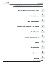
Page 5: ...4 5 6 7 8 9 C o n t e n t s C o n t e n t s Units installation Spare parts Water pipe installation Available optional functions Servicing Electrical wiring connections and diagram Test run Model codification and accessory codes Control system Troubleshooting ...

Page 6: ......

Page 7: ...nimum water volume description 35 2 2 2 Correction factor due to use of glycol 37 2 3 Water control 37 2 4 Water check valve 38 2 5 Accessories hydraulic installation 39 2 5 1 Pump kit 39 2 5 2 WEH Water Electric Heater 40 2 5 3 DHWT Domestic Hot Water Tank 42 2 5 4 Water drain discharge connection 44 3 Electrical wiring connections and diagram 45 3 1 General check 46 3 2 Electrical wiring connect...

Page 8: ...ation CONF 5 80 4 2 Supply setpoint calculation 81 4 3 Heating control functions 82 4 3 1 Heating Circuit General 82 4 3 2 Heating Characteristic Curve OTC Control 82 4 3 2 1 Room Setpoint Parallel Shift 83 4 3 2 2 Room Temperature Compensation 84 4 3 3 Heating Circuit Minimum Maximum Temperature Limits 84 4 3 4 Heating Circuit Secondary Pump 85 4 3 5 Automatic No Load Function 85 4 4 DHW control ...

Page 9: ... 4 8 3 Mixed Heating Circuit Maximum Temperature Limit Protection 102 4 8 4 Mixing Valve Opening Delay 102 4 9 General functions 103 4 9 1 System Frost Protection 103 4 9 2 Automatic Summer Switch Off 103 4 9 3 Pump and Valve Seizure Protection 104 4 9 4 Screed Function Drying for New Floors 104 4 10 Parameter tables 105 4 10 1 Installer Parameters 105 4 10 1 Engineering Parameters 106 4 11 Conver...

Page 10: ...MMI Pack Room unit and RF receiver 129 4 22 1 Room Unit installation guide 129 4 22 1 1 Description 129 4 22 1 2 Installation information 130 4 22 1 3 Installing the System MMI Pack 130 4 22 1 4 Installing the RF Receiver 131 4 22 2 Installing the Room Unit 132 4 22 2 1 Power up 132 4 22 2 2 RF Communication check test mode 132 4 22 2 3 Locating the Room Unit 133 4 22 3 Communication loss 133 4 22...

Page 11: ... procedure for Yutaki 158 6 2 1 System controller testing 160 7 Troubleshooting 165 7 1 Initial troubleshooting 166 7 1 1 Unit and System controller Power Supply failure 166 7 1 2 Abnormal operation of the devices 168 7 1 3 Incidents of operation 174 7 2 Troubleshooting procedure 175 7 2 1 Alarm code 177 7 3 Failure diagnosis method 216 7 4 Checking procedure for main parts 218 7 4 1 RHUE 3 6 AVHN...

Page 12: ...1 4 Removing the lower part of service panel and rear panel 240 9 1 5 Removing Yutaki fan motor 241 9 1 7 Removing the compressor 242 9 1 6 Mounting Yutaki fan motor 242 9 1 8 Removing high pressure switch 245 9 1 9 Opening electrical box P mounting plate 246 9 1 10 Removing the coils for the reversing and solenoid valves 247 9 1 11 Removing electronic expansion valve coils 248 9 1 12 Removing pre...

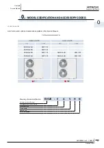
Page 13: ...TS AHN UNITS Unit Code Unit Code RHUE 3AVHN 9E311100 RHUE 4AVHN 9E411100 RHUE 5AVHN 9E511100 RHUE 5AHN 9E531100 RHUE 6AVHN 9E611100 RHUE 6AHN 9E631100 1 3N Meaning of model codification RHUE 5 A V H N Unit type made in Europe Compressor power HP 3 4 5 6 Air to water unit Single phase Heating only R410A Refrigerant 0 model codification and accessory codes Unit code list ...

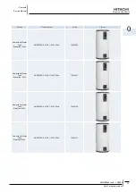
Page 14: ...on Code Figure STE1 Water temperature sensor 9E500004 RMPID1 Extension controller 9E500005 Pump Kit A Pump kit A TOP S 25 7 9E500006 Pump Kit B Pump Kit B TOP S 25 10 9E500007 EH61 Heater 6 kW EH61 BDHM1 Hydraulic separator BDHM1 VID3V1 3 way valve VID3V1 CDH2Z1 Disconnection vessel CDH2Z1 ASMSH1 Aquastat ASMSH1 ...

Page 15: ...e Domestic Hot Water Tank Enamelled 200L DHWT200E 2 5H1E 1 230V 50Hz 70544000 Domestic Hot Water Tank Enamelled 300L DHWT300E 2 5H1E 1 230V 50Hz 70544001 Domestic Hot Water Tank Stainless 200L DHWT200S 2 5H1E 1 230V 50Hz 70544100 Domestic Hot Water Tank Stainless 300L DHWT300S 2 5H1E 1 230V 50Hz 70544101 ...

Page 16: ......

Page 17: ...concerning the installation of Yutaki units Contents 1 1 RHUE 3 6 A V HN 17 1 1 1 Transportation 17 1 1 2 Center of gravity 18 1 1 3 Installation space 19 1 1 4 Place provision 20 1 1 5 Optional parts 22 1 2 Accessories Installation 27 1 2 1 Pump kit 27 1 2 2 WEH Water Electric Heater 28 1 2 3 DHWT Domestic Hot Water Tank 30 ...

Page 18: ...the stop of the unit before to start any cleaning or maintenance operation allowing the discharge of the condensers caution Malfunction Unit failure When installing more than one unit together keep clearance of more than 500 mm between units and avoid obstacles that could hamper air intake Malfunction Short circuit Keep cleareance of more than 3000 mm between the wall without vent holes and air in...

Page 19: ... shown in the figure below Over 60º 0 7 to 1 0 m Do not remove the plastic band or the corrugate paper frame Pass the wire ropes through each lifting hole in the wooden base as shown Wire rope warning Crush hazard Can cause seriour injury Lift the unit with 2 wire ropes and without removing its factory packaging Make sure that the unit is lifted smoothly and does not lean Do not attach lifting equ...

Page 20: ...to prevent its overturning Pay attention to the center of gravity shown in the below figure Center of gravity Unit model Operation weight kg Center of gravity position mm a b h RHUE 3AVHN 130 705 223 545 RHUE 4AVHN 130 705 223 545 RHUE 5AVHN 135 695 228 560 RHUE 5AHN 140 695 228 560 RHUE 6AVHN 139 695 228 560 RHUE 6AHN 144 695 228 560 Note It is recommended that at least two people participate whe...

Page 21: ... 1 2H A 350 1 2H L H A 450 H 1380 0 L 1 2H A 600 1 2H L H A 1200 H 1380 H 1380 0 L 1 2H A 600 1 2H L H A 1200 H 1380 Around sides are closed 500 500 50 500 Around sides are open with obstacles above Around sides are open Around sides are open with obstacles above 0 L 1 2H A 350 1 2H L H A 450 H 1380 0 L 1 2H A 600 1 2H L H A 1200 H 1380 Unit mm Note All measuring units are in milimetres mm ...

Page 22: ...me slippery Drain water 900 1250 1450 174 410 440 640 Drain water place Concrete base Foundation bolt Mortar charge The whole of the base of the Yutaki unit should be installed on a foundation When using vibration proof mat it should also be positioned the same way When installing the Yutaki unit on a fieldsupplied frame use metal plates to adjust the frame width for stable installation as shown i...

Page 23: ... product with a shallow depth It may also be able to fix on the wall as shown below when fixing only with the foundation bolt does not seem sufficiently stable depending on the conditions of the installation Metal fittings must be field supplied Fix unit to the wall 1 Fix the unit onto the wall as indicated in the figure Stay field supplied 2 The foundation shall be strong enough to avoid any defo...

Page 24: ...recommended to use the optional parts see section Optional parts and installation for RHUE 3 6 A V HN Adverse strong wind Air flow Adverse strong wind caution Strong wind Damage to fan motor Excessive strong wind against the unit outlet may cause inverse rotation and damage the fan motor 1 1 5 Optional parts Air flow guide wind guard and snow protection hood Optional parts HP Model Air flow guide ...

Page 25: ...ocated at 4 positions on the grille Screw tightening torque 2 4 3 1N m Do not remove the air discharge grille for air flow guide installation warning Rotating fan blades Risk of cut If the air guide is installed without discharge grille it may cause injury due to rotating fan Two windbreak covers installation Outdoor unit M5 fixing screw x4 M5 fixing screw x4 Accessories Accessories Air discharge ...

Page 26: ...ttaching example of air wind guard Attach the air flow guide to the air discharge grille with four 4 screws supplied The fixing holes are located at 4 positions on the grille Screw tightening torque 2 4 3 1N m Do not remove the air discharge grille for air flow guide installation caution Rotating fan blades Risk of cut If the air guide is installed without discharge grille it may cause injury due ...

Page 27: ... Fixing screw Accessories Hole for safety wire rope to prevent overturning Fixing screw Accessories Upper right side plate 1 Upper left side plate 1 Upper front panel Upside 1 Upper front panel Downside 1 Lower right side plate 1 Lower left side plate 1 Upper front panel Upside 1 Upper front panel Downside 1 Left suction hood No Part name Qty Fixing hole x 2 Fixing screw Accessories Enlarged view ...

Page 28: ... unit Material Bonderized steel sheet Iron Stainless SUS304 Bonderized steel sheet Iron Stainless SUS304 Bonderized steel sheet Iron Stainless SUS304 Color Gray 1 0Y8 5 0 5 or approximation Gray 1 0Y8 5 0 5 or approximation Gray 1 0Y8 5 0 5 or approximation Weight 3 kg 14 kg 8 kg Assembling Knockingdown parts assembled at field Components Hood For air discherge part x 1 For rear side air intake x ...

Page 29: ...n adverse effect on the functioning of the pump The flow direction of the pump must correspond to the directional arrow on the pump housing caution Crash damage Risk of damage to the O ring When turning the motor housing round ensure the O ring between the can pot and the pump housing does not become damaged The O ring must not be turned and must remain at the edge of the can pot pointing towards ...

Page 30: ...roducts as close as possible to the installation location before unpacking Check the contents of the package WEH 6E Installation and Operation Manual 2 M6x15 screw and 2 M6 washers Wall fixing support Selection procedure for YUTAKI units NOTE WEH appliance must be installed in an indoor place WEH installation must be done by professional installers Install the WEH with sufficient clearance around ...

Page 31: ...nce Place provision Drill 2 holes Ø 8mm on the wall for fixing WEH according to the dimensions of the Wall Support attached Fixed supplied support to the wall by using previous drill holes Use attached screws for fixing WEH to the supplied support Check that WEH are installed horizontally For cleaning use non flammable and non toxic cleaning liquid The use of flammable agents should cause explosio...

Page 32: ...ection aperture 1 HSW storage tank 1 External covering 1 Top cover 1 Thermal insulation 1 Control panel 1 Electrical Heater 1 Heating coil 1 Sensor probe DHWT 200 300 E 2 5H1E Ref Qty Name 1 Inspection aperture 1 HSW storage tank 1 External covering 1 Top cover 1 Thermal insulation 1 Control panel 1 Electrical Heater 1 Heating coil 1 Sensor probe 1 Cathodic protection anode ...

Page 33: ... install the WEH where there is a high level of oil mist salty air or sulphurous atmosphere When installing some device next to WEH keep clearance between WEH and any other obstacle of more than 500mm caution Insufficient ventilation Can cause oxygen deficiency Working with insufficient ventilation in an enclosed space can produce toxic gas especially when cleaning agent is heated to high temperat...

Page 34: ......

Page 35: ...or Yutaki units Contents 2 1 General notes 34 2 2 Piping work connection considerations 35 2 2 1 Minimum water volume description 35 2 2 2 Correction factor due to use of glycol 37 2 3 Water control 37 2 4 Water check valve 38 2 5 Accessories hydraulic installation 39 2 5 1 Pump kit 39 2 5 2 WEH Water Electric Heater 40 2 5 3 DHWT Domestic Hot Water Tank 42 2 5 4 Water drain discharge connection 4...

Page 36: ...ened under normal circumstances If this cock is opened during operation trouble will occur due to water blow off When necessary put insulation on the pipes in order to avoid heat losses 6 When the unit is stopped during shutdown periods and the ambient temperature is very low it is possible that the water 7 in the pipes and in the circulating pump freeze thus damaging the pipes and the water pump ...

Page 37: ...teristics and water equipment might be damaged When connecting several units to a common pipe its design should ensure that the water flow on each unit is the same see below figure Imbalance of water distribution may cause a serious damage like water freezing in the plate heat exchanger Yutaki unit Indoor installation heating elements Working condition Pressure range 0 MPa 1 0 MPa Water temp range...

Page 38: ...ansion tank Pump Yutaki unit Buffer tank Load system Note 2 Shortage Minimum water volume Water volume in circulation system The following part shows the minimum water volume in the system for product protection and temperature drop during defrost operation Protective water volume for product 1 Ensure that the water volume is equal or greater than those shown below in order to reduce ON OFF freque...

Page 39: ...he unit will be damaged by freezing water in the pipes and in the circulating pump during the shutdown periods In order to prevent this it is useful to empty the water from the installation or to maintain the supply to the installation as an electric cord can prevent the water from freezing in the circuit Additionally in cases where water drainage is difficult an antifreeze mixture of ethylene gly...

Page 40: ...than 1 0 Less than 0 1 Sulphur ion mg S2 I It shall not be detected Ammonium ion mg NH4 I Less than 1 0 Less than 0 1 Remaining chlorine mg CI I Less than 0 3 Less than 0 3 Floating carbonic acid mg CO2 I Less than 4 0 Less than 4 0 Index of stability 6 8 8 0 Note The mark in the table means the factor concerned with the tendency of corrosion or deposits of scales The value showed in are for refer...

Page 41: ...nstall in horizontal pipework with test plugs directed downwards This position ensures optimum protection efficiency and 3 is the best for testing the valve Shutt off valves should be fitted on each side of the check valve for easier and faster valve testing 4 The installation location should be protected against frost and be easily accessible 5 2 5 Accessories hydraulic installation 2 5 1 Pump ki...

Page 42: ...lectric Heater Hydraulic circuit General notes When Piping connections are performed Connect all pipes as close as possible to the unit so that disconnection can be easily performed when required 1 It is recommended to use flexible joints for the piping of water inlet and outlet so vibration will not be transmitted 2 Whenever possible sluice valves should be installed for water piping in order to ...

Page 43: ...1G Water OUT Water IN 1G 1 4G Inlet and outlet connection pipes must be 1G It must be kept the water flow direction indicated in previous drawing Note Check periodically Water flow and pressure Water leakages Fixing points tightening Minimum water volume description Necessity of water in system The following problems should occur when the quantity of water in the forced circulation system 1 on wat...

Page 44: ...ly performed when required 1 It is recommended to use flexible joints for the piping of water inlet and outlet so vibration will not be transmitted 2 Whenever possible sluice valves should be installed for water piping in order to minimise flow resistance and to 3 maintain sufficient water flow It is recommended to apply ball valves in both water pipe connections to make easier any maintenance wor...

Page 45: ...T installation The nominal pressure of the safety unit will be 8 bar When the main pressure is more than 6 bar a pressure reducer should be installed The water discharge during heating expansion is normal The volume of this discharge can be up to 3 of the storage tank s capacity The pressure regulator device must be working regularly depending on the quality of water in order to remove the lime s ...

Page 46: ...details Rubber cap Drain pipe Drain pipe Extruded portion Drain Boss Drain hole of Base Model Applicable Model DBS 26 RHUE 3 6 A V HN Connection procedure Insert the rubber cap into the drain boss up to the extruded portions 1 Insert the boss into the unit base and turn approximately 40 degree counterclockwise 2 The outer diameter section of the drain boss is 32 mm 3 A drain pipe should be field s...

Page 47: ...ck 46 3 2 Electrical wiring connection 47 3 2 1 Field minimum wire sizes for the power source 48 3 2 2 Main switches and fuses 49 3 3 Setting the DIP switches 49 3 4 LED indication 53 3 5 Accessories electrical installation 54 3 5 1 Pump kit 54 3 5 2 WEH Water Electric Heater 57 3 5 3 DHWT Domestic Hot Water Tank 59 3 6 Electrical wiring diagrams 65 3 6 1 Electrical wiring diagram for models RHUE ...

Page 48: ... protect the product from any condensed water and insects Tightly secure the wires with the cord clamp inside the unit Lead the wires through the knockout hole in the side cover when using conduit Secure the cable of the remote control switch with the cord clamp inside the electrical box Electrical wiring must comply with national and local codes Contact your local authority in regards to standard...

Page 49: ...ing with IEC 61000 3 12 RHUE 3AVHN RHUE 4AVHN RHUE 5AVHN RHUE 6AVHN Check that the power supply voltage is within 10 of the rated voltage And that power supply has an impedance low enough to avoid reducing the starting voltage more than 85 of the rated voltage 3 2 Electrical wiring connection Main controller Non voltage Power supply 1 230V 50 Hz 3N 400V 50 Hz for RHUE 5 6 AHN Earth wiring Power su...

Page 50: ...1 CN2 1 LED8 CN4 CN3 CN5 OSC IC7 C21 CN6 CN11 C8 C9 R107 C19 IC4 2 LED7 IC8 1 EF3 Z5 DSW6 PC10 IC2 R137 ZD9 R135 R143 R138 REG7 C20 C4 3 REG4 DSW2 DSW5 DSW1 IC3 IC5 PSW2 2 2 3 4 1 2 PSW1 3 4 1 REG3 4 4 1 2 DSW3 3 5 1 2 3 4 DSW4 REG6 R3 R2 REG8 REG9 DM1 DM6 C2 DM8 C5 C6 C1 REG2 REG1 DM5 CN10B C7 DM7 CN10A 7 8 Z2 PCN3B PCN3A Z3 PCN2 X P Tr 1 Y52CS RSW4 RSW2 YE1 YA Y20A YE2 Y20B Y20L CN13 CN12 R110 C...

Page 51: ... DIP switches location on the PCB Upper side shows unit status Lower side shows discharge and suction pressure value alternatively Status indication 1 Press the PSW2 more than 3 seconds to change the status display mode Alarm history 2 Press the PSW1 and PSW2 together more than 3 seconds to switch to alarm history mode Note The mark indicates the position of dips switches No mark or not available ...

Page 52: ...N DSW1 DSW2 DSW3 DSW4 1 2 3 4 5 7 6 8 1 2 3 4 5 7 6 8 1 2 3 4 5 7 6 8 1 2 3 4 5 7 6 8 1 2 3 4 5 7 6 8 1 2 3 4 5 7 6 8 DSW5 DSW6 1 2 1 2 1 2 1 2 1 2 1 2 DSW7 DSW8 DSW9 Rotary switches RSW1 RSW2 heating temperature setting RSW3 RSW4 SSW not used DSW1 optional functions Function Set PINs Factory setting PCB self checking Pump High cut test Optional functions setting mode Compressor enable ...

Page 53: ...oling mode Not available Heating only Not used Set temp by rotary switch Commissioning Set temp by system controller 4 to 20 mA DSW4 unit model confgurations Function Set PINs Not used 1 2 3 4 5 7 6 8 Not used 1 2 3 4 5 7 6 8 Heat pump 1 2 3 4 5 7 6 8 Yutaki heat pump 1 2 3 4 5 7 6 8 Not used 1 2 3 4 5 7 6 8 Not used 1 2 3 4 5 7 6 8 Not used 1 2 3 4 5 7 6 8 Not used 1 2 3 4 5 7 6 8 Function Set PI...

Page 54: ...t used DSW6 end resistance fuse recovery Function Set PINs Not used 1 2 Not used 1 2 DSW7 unit control configuration Function Set PINs Three phase Single phase Not used Inverter compresor Cancel zero reset expansion valve Liquid injection enable DSW8 Pd DSW9 Ps setting Pd Ps pressure sensor type Function Set PINs Not used Pressure sensor R410A ...

Page 55: ...ble If this function is Enable in case of power failure the unit will restart automatically once the power is recovered 1 Disable 3 4 LED indication LED1 LED2 and LED3 Power supply indication Status LED1 LED2 LED3 Power supply ON ON OFF OFF Power supply OFF OFF OFF OFF Not available for Yutaki LED4 Operation status indication Status LED4 Unit stopped OFF Unit running ON Alarm OFF LED5 Alarm indica...

Page 56: ...ssories electrical installation 3 5 1 Pump kit Yutaki is controlling the pump by itself The pump kits A or B must be always connected according to the wiring below Only for TOP S 25 10 To pump Model Protection type Cut out Connection terminals TOP S 25 7 Auto reset 1 230 V 50 Hz TOP S 25 10 Manual reset ...

Page 57: ...t Remove the front cover according to the procedures described in main parts caution Contamination Risk of poisoning The pumps must not be used for drinking water or food stuffs Electrical connection Danger Electrical hazard Can cause serious injuries or death All electrical connections must be completed by a qualified and licensed electrician in strict compliance with local regulations Before wor...

Page 58: ...TOP S 25 7 1 230V P1 max 245W Internal switch off of the motor main power supply Auto reset once the motor has cooled down the pump will automatically switch back on Speed adjustment switch 3 settings TOP S 25 10 1 230V 330W P1 max 400W WSK and external switch SK602 SK622 C SK or other control unit Manually at the external switch box once the motor has cooled down Speed adjustment switch 3 setting...

Page 59: ...s are switched OFF Check that the earth wire is securely connected tagged and locked in accordance with national and local codes Check and test to ensure that if there is more than one source of power supply that all are turned OFF Check to ensure that the screws of the terminal block are tightly tightened Crash hazard Can cause serious injuries Check to ensure that Yutaki fans are stopped before ...

Page 60: ...W Alimentation Supply 3N 400V 50 Hz 3N N Alimentation Supply 1 230V 50Hz 1 N System Controller Output 2 1 230V 50Hz System Controller Output 1 1 230V 50Hz Immersion heater System Controller System Controller Terminal Block A outputs System Controller Terminal Block A LPSW Ground wires note This connection is only for the electric heater EH 61 Wiring size Connection wiring The minimum thickness of ...

Page 61: ...eath Do not connect or adjust any wiring or connections unless the main power switch is OFF Make sure that all the power sources are switched OFF Check that the earth wire is securely connected tagged and locked in accordance with national and local codes Check and test to ensure that if there is more than one source of power supply that all are turned OFF Check to ensure that the screws of the te...

Page 62: ...mer connection Wire size Recommended minimum sizes for field provided Model Power Source Max Current Power source cable size Control cable size CB ELB Number of poles A mA EN60 335 1 EN60 335 1 DHWT 1 230V 50Hz 15A 2 5mm 1mm 20A 2 40 30 Notice Follow local codes and regulations when selecting field wires Circuit Breakers and Earth Leakage Breakers Use the wires which are not lighter than de ordina...

Page 63: ...r cable Control cable To system control unit Main switch Ref Name WT Regulating and Safety thermostat Re Auxiliary Relay SW1 Operating Mode switch R 123 Electrical Heater LD1 LED1 POWER ON LD2 LED2 AUTO MODE ON LD3 LED3 Electrical Heater Manual TB Terminal Board L N T Power supply 3 4 Control Heater Input 5 6 Electrical Heater Connection ...

Page 64: ...4 2 3 7 6 In order to protect the inside of the vessel from corrosion all the enamelled DHWT can be equipped whit a cathodic protection unit comprising magnesium sacrifice anodes charge gauges and wiring of connection It basically comprises a magnesium anode 1 mounted on the storage tank s connection plate 2 connected to the external anode load measured 3 which allow to know the anode consumption ...

Page 65: ...he button If the gauge is in the red zone the magnesium anode must be replaced Do not install the permanent cathode protection and the cathodic protection together Titan protection accessory 6 1 5 2 4 7 8 9 10 3 11 All the Hitachi DHWT can be equipped with the permanent cathode protection system which is totally automatic and maintenance free It basically comprises a titanium anode 1 mounted on th...

Page 66: ...ect the protection system during periods of absense holidays etc Occasionally check that the pilot light is working correctly 11 Electric heater The electric heater is made of Incoloy alloy 825 and complies with the European Low Voltage Directive 2006 95 EC It comprises a flange that holds three U Shaped heating elements for 2 5kw power resistances Replace electric heater The steps to be followed ...

Page 67: ...onvection flow safety device for liquids in circulation etc DHWT 200 300 S 2 5H1E Ref Name To terminal 5 and 6 of the control panel To the top flange To earth terminal of the control panel Flange Heater Seal Washers Screws Studs Nuts Metal protective casing Screws M6 Panel Screws M4 Wires Earth Wire DHWT 200 300 E 2 5H1E Ref Name Heater connection To terminal 5 and 6 of the control panel To the to...

Page 68: ...or Compressor Contactor for Compressor Motor for Fan Motor for Compressor 1 2 C2 NF DIP IPM 1 PF 52P P EF OFF BSR RL OL ON BSR E P X DC R 21 30 CE WH 20I R1 EF PWB1 1 2 3 4 OH 1 14 DCL C1 NF MV MVC 21 2 MF1 DS 1 10 CS ON BS OFF BS 1 2 Tr a THM ec s THM THM d eh THM THM 1 5 NK 52C 20G PS L PS H THM THM PWB2 Wo Wi 2 1 63H TB TB CE MC Earth Line Connection Line Connection Line Connection Line Connect...

Page 69: ...it DC R 21 30 CE WH 20I R1 EF 47C 1 2 R C1 1 2 CB PWB5 PWB3 4 PWB1 1 2 3 4 OH 1 18 ISPM DCL C1 NF MV MVC 21 1 2 C2 C3 NF 2 MF1 DS 1 10 CS ON BS OFF BS 1 2 Tr a THM ec s THM THM d eh THM THM 1 5 NK 52C 1 2 PF 20G PS L PS H THM THM PWB2 Wo Wi 2 1 63H TB TB CE MC Name of Parts Terminal Board for Power Supply H Link RL OL OFF BS E ON BS EF P X P Pilot Lamp Power Fuse for Pump Push Button Switch for St...

Page 70: ......

Page 71: ...point calculation 81 4 3 Heating control functions 82 4 3 1 Heating Circuit General 82 4 3 2 Heating Characteristic Curve OTC Control 82 4 3 2 1 Room Setpoint Parallel Shift 83 4 3 2 2 Room Temperature Compensation 84 4 3 3 Heating Circuit Minimum Maximum Temperature Limits 84 4 3 4 Heating Circuit Secondary Pump 85 4 3 5 Automatic No Load Function 85 4 4 DHW control functions 85 4 4 1 DHW Storage...

Page 72: ...2 4 8 3 Mixed Heating Circuit Maximum Temperature Limit Protection 102 4 8 4 Mixing Valve Opening Delay 102 4 9 General functions 103 4 9 1 System Frost Protection 103 4 9 2 Automatic Summer Switch Off 103 4 9 3 Pump and Valve Seizure Protection 104 4 9 4 Screed Function Drying for New Floors 104 4 10 Parameter tables 105 4 10 1 Installer Parameters 105 4 10 1 Engineering Parameters 106 4 11 Conve...

Page 73: ...r 129 4 22 System MMI Pack Room unit and RF receiver 129 4 22 1 Room Unit installation guide 129 4 22 1 1 Description 129 4 22 1 2 Installation information 130 4 22 1 3 Installing the System MMI Pack 130 4 22 1 4 Installing the RF Receiver 131 4 22 2 Installing the Room Unit 132 4 22 2 1 Power up 132 4 22 2 2 RF Communication check test mode 132 4 22 2 3 Locating the Room Unit 133 4 22 3 Communica...

Page 74: ...vice Manual 72 Contents SMGB0066 rev 0 12 2009 4 23 Device control system 143 4 24 Yutaki unit PCB 144 4 25 Safety and control device setting 145 4 25 1 Defrost operation control 147 4 25 2 Control of expansion valve 149 ...

Page 75: ...d The System Controller may only be installed and mounted by authorised and suitably trained personnel If the unit is modified in any way except by the manufacturer all warranties concerning operation and safety are invalidated Make sure that local standards and regulations are respected at all times Use only accessory equipment that comes from or has been approved by Honeywell or Hitachi caution ...

Page 76: ...3 x Water Temperature Sensors 1 x Outside Temperature Sensor Sensors connect directly to System Controller 4 1 4 Quick start installation steps Select which type of system you wish to install 1 Determine where the various system components should be installed 2 Mount the system components for System Controller and Sensors see installation instructions in the System MMI 3 Pack Connect the Sensors R...

Page 77: ...atus SSUP Overall system supply setpoint S1 Zone 1 supply setpoint SR1 Zone 1 room temperature setpoint S2 Zone 2 supply setpoint DSET DHW setpoint SDHW DHW supply setpoint 4 1 6 Application configurations The System Controller can be used for several different hydraulic system configurations including mono valent systems mono energetic systems with auxiliary electric heater and bi valent systems ...

Page 78: ...lance point A 0 5K control differential is applied to the switching between the operating modes Outdoor temperature TEXT Balance Point BP 0 5K the boiler or electric heater is not used Exception is that the boiler can be used for DHW loading Outdoor temperature TEXT Balance point BP 0 5K the system controller determines whether to switch on the boiler or electric heater depending on the heating re...

Page 79: ...ant Note P14 should never be set higher than P15 otherwise incorrect operation will result 4 1 8 Mono Valent Systems CONF 1 Summary In mono valent systems the heat pump is the sole provider of heating energy to the system The Heat Pump is sized to provide 100 of the heating requirements on the coldest day of the year It is recommended for low energy houses and for moderate climates without severe ...

Page 80: ...ons Important Parameter Settings CONF 2 P1 0 1 2 according to DHW system type P2 0 1 according to whether a buffer tank hydraulic separator and secondary pump is installed P4 heating curve according to building and system characteristics P33 5K electric heater return high limit offset The Electric Heater Return High Limit is an important check to help ensure that the heat pump operates as much as ...

Page 81: ...r hydraulic balancing This system is recommended for retrofit upgrade applications where an existing gas oil boiler will be retained to provide the full heating requirements on the coldest days of the year Important Parameter Settings CONF 3 P1 0 1 2 according to DHW system type P4 heating curve according to building and system characteristics It is also recommended to review all parameter setting...

Page 82: ...with DHW mixed heating loop Hydraulic separator or buffer tank CONF 4 Bi valent Parallel system 4 1 12 Bi Valent System Serial Operation CONF 5 Summary This is a bivalent system where the boiler is configured in series with the heat pump A hydraulic separator or buffer tank has to be used to ensure proper hydraulic balancing This system is also used for retrofit upgrade applications but operates l...

Page 83: ...ntrolled by the Extension Controller DHW zone The DHW storage tank loading loop Each zone can generate a demand to the heat pump and or boiler electric heater for a particular supply water temperature S1 The supply setpoint water temperature required by the zone 1 heating loop S2 The supply setpoint water temperature required by the zone 2 heating loop SDHW The supply setpoint water temperature re...

Page 84: ...lways try to provide the correct water temperature to maintain the desired comfort conditions based on the heating characteristic curve as described below However the heating circuit is disabled when DHW storage tank loading is required or the summer switch off condition is active or the no load condition is active 4 3 2 Heating Characteristic Curve OTC Control Function The System Controller is an...

Page 85: ...s the supply water temperature setpoint when the room setpoint 20 C and no room compensation is applied Outside Temperature ºC Supply water temperature ºC Example P4 1 1 TEXT outside temperature 0 C SR1 room setpoint 20 C From graph S1 supply setpoint 49 C 4 3 2 1 Room Setpoint Parallel Shift Function At different times of the day according to the time programme in the Room Unit the room temperatu...

Page 86: ...the end user on the Room Unit Please refer to the System MMI Pack Installation and Operation Manual for further details Note Room compensation should not be used when the room unit is located in a position unrepresentative of the desired temperature in the living spaces for example in a warm cupboard The room setpoint and room temperature values are sent from the Room Unit to the System Controller...

Page 87: ... pump CONF 3 4 5 Secondary pump control is always enabled CONF 4 5 If the mixed circuit maximum temperature limit is active then the secondary pump is switched off 4 3 5 Automatic No Load Function Function When the calculated supply temperature setpoint from OTC heating curve room setpoint shift room compensation shift is less than the room temperature then the heating circuit can be switched off ...

Page 88: ...ture drops below the DHW setpoint minus the DHW differential P11 this function switches on the DHW Pump or opens the DHW valve and sets a supply setpoint equal to DHW setpoint DHW supply offset P12 The DHW loading is complete when the DHW temperature rises above the DHW setpoint Supply Setpoint for DHW loading DHW setpoint DHW Supply Offset P12 DSET DHW setpoint P10 SDHW Supply Setpoint for DHW lo...

Page 89: ...HW setpoint may be set higher since the boiler will also be used to heat the DHW storage tank P11 DHW differential A small DHW differential will increase the frequency of the DHW loading periods while making them shorter A large DHW differential will reduce the frequency of the DHW loading periods while making each period longer and will cause larger swings in DHW temperatures P12 DHW supply offse...

Page 90: ...ric heater for situations when the heatpump is unable to fully load the DHW tank The Heat Pump is not able to heat the DHW tank to high temperatures by itself because its output is limited The maximum temperature to which the heat pump can raise the DHW tank is defined as DSET_HP the maximum temperature to which the heat pump can heat the DHW tank Heat Pump maximum supply temperature EP29 or EP33 ...

Page 91: ...e its own thermostat set to a higher value than the DHW setpoint of the System Controller Please take care about the type of DHW storage tank fitted and the position of the electric heater 4 4 4 2 Using the Boiler for DHW loading Configuration Specific Applies only to configurations CONF 3 5 Function The boiler may also be used to raise the temperature of the DHW tank if the Heat Pump is not able ...

Page 92: ...P35 When this time period expires the Supply Setpoint is set to the normal calculated DHW supply setpoint Parameter Setting EP35 Heat Pump Max Time High Setpoint default 180sec Note Engineering Parameters EP are only available for service engineers 4 4 7 DHW Time Program Function A DHW time program is not provided inside the controller An external timer can be used by itself or together with a tar...

Page 93: ...rcuit The Heat Pump on off output of the System Controller is connected to the Remote on off input of the heat pump The heat pump will start the water circulation pump primary pump when the remote on off input is switched on and enable its internal control of the compressor and heat pump system components The System Controller switches the heat pump off when the outdoor temperature TEXT 20 C adjus...

Page 94: ...at Pump Supply Setpoint at 4mA default 20 C EP7 Heat Pump Supply Setpoint at 20mA default 55 C These parameters should only be changed with the approval of the manufacturer Note Engineering Parameters EP are only available for service engineers 4 5 3 Heatpump Sensor Offset Function In practice there may be a difference between the heat pump outlet temperature measured by the Heat Pump and the supp...

Page 95: ...perature to the Heat Pump rises above 65 C it will generate a system fault excessively high water temperature To prevent this happening the System Controller will directly switch off the heat pump if the return temperature rises above a set limit Return water temperature TRET EP13 0 5K Heat Pump is switched off Return water temperature TRET EP13 0 5K Heat Pump may be switched on Parameter Settings...

Page 96: ...on Specific The tariff switch input heat pump blocking is only allowed for Bi Valent systems For mono valent or mono energetic systems the heat pump can never be blocked by this input Function This function allows an external tariff switch device to switch off the heat pump during times of peak electricity demand When the controller is working in bi valent mode the boiler will be switched on to pr...

Page 97: ...cked by the Tariff Timer input Boiler Setpoint Supply Setpoint Control Offset If the heat pump is switched off or has an internal fault the Boiler Setpoint Supply Setpoint SSUP If the heat pump is switched on the water setpoint used for the boiler control depends on the value of the Supply Setpoint When the supply setpoint is low the boiler will only be used if the actual supply temperature is muc...

Page 98: ...ter than the Supply Return Difference Limit P32 A 0 5K control differential is applied TSUP TRET P32 0 5K Boiler is allowed to switch on TSUP TRET P32 0 5K Boiler is not allowed to switch on When the boiler starts from cold the supply temperature can drop for a small time as the cold water in the heat exchanger is pumped into the system This function would then cause the boiler to be switched off ...

Page 99: ...e starts When the heat pump is switched on or When the boiler switches off but only also when the Supply Setpoint SSUP heat pump maximum temperature heat pump sensor offset This means that when the heatpump should normally be able to meet the heating demand on its own the boiler waiting time applies but when the supply setpoint is so high that the heat pump cannot meet the heating demand on its ow...

Page 100: ...ric heater has been manually released after a heat pump fault In addition two further checks are made before the electric heater is allowed to switch on The purpose of these checks are to help ensure that the electric heater only switches on when the heat pump is working at its maximum capacity the Supply Return Difference Check 1 the Electric Heater Return High Limit Check 2 These checks are not ...

Page 101: ...d Load Boiler Electric Heater Control default 6 K 100 EP20 Inter Stage Waiting Time default 10 sec EP31 supply Setpoint Control Offset default 4 K It is not normally recommended to change these parameters They have been selected during laboratory tests for best performance in most situations Correct positioning of the Supply Temperature Sensor close to the outlet of the Electric Heater should resu...

Page 102: ...wn the waiting time does not apply Parameter Settings P19 Waiting Time for Electric Heater default 30min A higher value of P19 will reduce the number of times that the electric heater is used at lower supply setpoints but the desired supply temperature may not be reached quickly if there is a high heating load slower response Conversely a lower value of P19 will increase the number of times the el...

Page 103: ...Valve Control Configuration Specific This function only applies to configuration 4 CONF 4 Function When heating is required the System Controller controls the mixing valve so that the mixed water temperature is close to the Supply Setpoint The mixing valve position is calculated with a proportional plus integral action P I control algorithm based on the difference between the Supply Setpoint and m...

Page 104: ...xing control continues to operate Parameter Setting P9 Mixing Valve Runtime default 120 sec EP3 Difference Supply water temperature default 1 5K The value for EP3 has been chosen based on laboratory tests and it is not recommended to change it Note Engineering Parameters EP are only available for service engineers 4 8 3 Mixed Heating Circuit Maximum Temperature Limit Protection Configuration Speci...

Page 105: ... falls below the parameter P22 the supply water temperature will be maintained at least at the parameter value P21 A switching differential of 1K is applied Outside temperature TEXT P22 Supply Setpoint SSUP determined by heating or DHW demand but always P21 Outside temperature TEXT P22 1K Supply Setpoint SSUP determined by heating or DHW demand Parameter Settings P21 Frost Protection minimum Suppl...

Page 106: ... on floor heating systems The process is based on EN 1264 part 4 When the screed function is activated The flow temperature is kept constant at 25 C for 3 days 1 Heating is set at the maximum supply setpoint P6 for 4 days 2 water temperature is always limited to 55 C On completion of the screed function the controller returns to normal operation To Activate The function is activated by setting par...

Page 107: ... Influences how quickly the hot water tank is heated 1 30 1 10 K P15 Maximum Outdoor Temperature for Boiler Electric Operation 2345 Boiler Electric heater will be disabled above this temperature Heat Pump works on its own OFF means the boiler electric heater is always enabled 20 20 then OFF 1 0 C P14 Heat Pump Minimum Outdoor Temperature Config 3 4 5 only 345 Heat Pump Operating Limits Defines the...

Page 108: ...offset for Heat Pump maximum supply temperature 12345 The maximum DHW temperature able to be supplied by the heat pump is the Heat Pump maximum supply temperature minus this EP37 value 0 20 1 7 K CONF Only parameters that are allowed in a particular configuration are shown on the display 4 10 1 Engineering Parameters Function Engineering Parameters EP are provided for service engineers or the manu...

Page 109: ...t pump 25 20 then OFF 1 20 C EP16 P band Required Load 2345 Electric Heater or Boiler Control the proportional band of the P I control algorithm 0 2 20 0 0 2 6 0K EP20 Inter Stage Waiting Time 2 Electric Heater Control The minimum time between switching stages of the electric heater 10 250 10 10sec EP28 Heat Pump Minimum Supply Temperature 12345 Heat Pump Operating Limits minimum supply temperatur...

Page 110: ...1 0 2989 111 0 793 7 49 0 1541379 8 0 109189 32 0 14511 72 0 2882 112 0 770 3 48 0 1432919 7 0 103194 33 0 13875 73 0 2779 113 0 747 7 47 0 1332091 6 0 97564 34 0 13270 74 0 2681 114 0 725 8 46 0 1238358 5 0 92274 35 0 12695 75 0 2587 115 0 704 7 45 0 1153525 4 0 87303 36 0 12148 76 0 2496 116 0 684 2 44 0 1073429 3 0 82628 37 0 11627 77 0 2409 117 0 664 5 43 0 999894 2 0 78232 38 0 11131 78 0 232...

Page 111: ...DHW electric heater enable output relay Potential free contacts 230Vac 1A All other output relays 230Vac 1A 3A total Tariff Timer Input Input for potential free contact rated 5Vdc switching current 1mA Heat Pump Fault Input Input for potential free contact rated 5Vdc switching current 100mA RF Receiver connection Serial communications according to OpenTherm technical specification v2 3 max 18V 23m...

Page 112: ...etaining screws 1 Pull the front cover off the mounting base 2 caution Crash hazard Wire damage Make sure that all connector pins and blocks are correctly located before pushing the front cover onto the base otherwise damage may occur To fit the front cover onto the mounting base Line up the mounting base and front cover 1 Push the front cover firmly onto the mounting base 2 Secure the front cover...

Page 113: ...ounting the Sensors 4 15 1 Water Temperature Sensor The water temperature sensor can be inserted into a suitable immersion well or strapped on to a pipe using the supplied metal clip Note For strap on mounting the metal clip must be used and tightened firmly to provide a good thermal connection A badly mounted sensor can cause control problems The best location for measuring the temperature and th...

Page 114: ...re Sensor s protective housing prevents the sun s rays from affecting the sensor If the sensor has been mounted on the south side of a house with large windows facing in this direction it is recommended that you remove the sun guard Do not mount the Outdoor Temperature Sensor in a protected area such as a wall niche or under the balcony It should be put on an open façade so that it can detect all ...

Page 115: ...mpartments of the mounting base On the left side the signal wiring is laid out inputs mainly sensors On the right side the power source and earth wiring are situated power and output relay contacts Note It is important that power supply lines are kept separate from signal data communications lines This is to minimise the risk of electrical interference 4 16 1 Wiring access ports Wiring holes for w...

Page 116: ...d are suitable for wires from 0 3 to 1 6mm2 The earth connector block D is suitable for wires from 0 3 to 2 7mm2 note In some applications there may be several input and output cables that cannot be connected directly within the system controller terminal blocks In such cases it is recommended that a separate wiring centre is used with an appropriate cover as necessary Mains power supply Terminal ...

Page 117: ...itive Connect the wires as shown Please refer to heat pump installation manual for terminal connections Three stage electric heater In a mono energetic system CONF 2 the electric heater is used if required to increase the supply water temperature P19 Waiting time for boiler electric heater 9 8 7 TERMINAL BLOCK A Output 1 Electric Heater N Output 2 Boiler In a Bi Valent System CONF 3 4 5 the boiler...

Page 118: ...system P2 Secondary Pump Selection CONF 1 2 P3 Pump Overrun Time TERMINAL BLOCK A Secondary Pump 4 3 Domestic Hot Water DHW The System Controller can use the heat pump and boiler bi valent systems to maintain the DHW storage tank at the DHW setpoint P10 P10 DHW setpoint P11 DHW control differential P12 DHW supply offset TERMINAL BLOCK A DHW Valve Pump 6 5 RF receiver box The RF Receiver is connect...

Page 119: ...ent systems only The input can be configured so that the heat pump is blocked disabled on either an open circuit or closed circuit condition P24 Configuration of Tariff Timer Input Note that the Tariff Timer input terminals 10 11 can be used for DHW Time Switching OR Tariff Switching not both P24 Open Circuit on terminals 10 11 Closed Circuit on terminals 10 11 0 Tariff Timer Input is ignored 1 He...

Page 120: ...s configuration is suitable for low temperature radiators and underfloor heating systems Important settings Set installer parameter CONF to value 1 Set installer parameter P1 to 0 no DHW 1 DHW valve or 2 DHW pump Set P4 OTC heating curve according to building system Additional settings Set installer parameter P2 to 0 no secondary pump 1 secondary pump9 if buffer tank or hydraulic separator is used...

Page 121: ...uirements on the coldest day of the year and will typically provide 90 95 of the heating requirements over the whole heating season An electric auxiliary heater is used to provide the additional heating required on cold days additional capacity and or higher temperature Used in new builds or in boiler replacement applications Direct OTC Controlled Heating Loop Optional DHW storage with diverting v...

Page 122: ... 14 13 Bi Valent parallel systems direct conf 3 This system is recommended for retrofit upgrade applications where an existing gas oil boiler will be retained to provide the full heating requirements on the coldest days of the year Direct OTC Controlled Heating Loop Sequence control of boiler and heat pump Optional DHW storage with diverting valve or pump Important settings Set installer parameter...

Page 123: ...ontrol of boiler and heat pump Important settings Set installer parameter CONF to value 4 Set P4 OTC heating curve according to building system Additional settings Boiler control parameters Mixing valve control parameters Minimum and maximum supply temperatures Room temperature compensation Frost Protection parameters Summer switch off setting Tariff Timer input configuration To select alternative...

Page 124: ...4 OTC heating curve according to building system Additional settings Boiler control parameters Mixing valve control parameters DHW setpoint and control parameters Minimum and maximum supply temperatures Room temperature compensation Frost Protection parameters Summer switch off setting Tariff Timer input configuration Heat Pump Boiler Secondary pump Bypass Mixing valve Optional DHW pump valve Term...

Page 125: ...heating Tariff Timer Symbol Displayed when external tariff timer blocking function is activated DHW Symbol Displayed when the system is heating the DHW storage tank Pump I Symbol Displayed when the primary boiler pump bi valent systems is running Pump II Symbol Displayed when the secondary pump if connected is running Fault Symbol Displayed in case of a fault The display will show the text FAUL an...

Page 126: ...ameters to allow a quick start up procedure The factory default settings are shown in the table on the next page Should it be necessary to adjust any of these parameter settings please refer to the table and follow the instructions below To enter Parameter Display mode from the Normal Operation mode press and buttons together for at least one second The display will show CONF to indicate that the ...

Page 127: ...er electric heater is always enabled 20 20 then OFF 1 0 C P17 Boiler minimum on time 345 Sets the minimum ON time of the boiler to reduce inefficient short cycling 1 30 1 2 min P18 Boiler minimum OFF time 345 Sets the minimum OFF time of the boiler to reduce inefficient short cycling 1 30 1 5 min P19 Waiting time for boiler electric heater 2345 Sets the minimum time the controller will wait after ...

Page 128: ...stem testing 4 20 1 System start up After the installation of sensors and outputs the System Controller controller can be started for the first time Switch on the mains power supply The controller will be initialised with the default configuration stored in the internal memory A test procedure is performed to check the validity of the data in the internal memory and the various inputs are tested A...

Page 129: ...o test the electrical connections To enter Output Display mode from Normal Operating mode press the SEL and SET buttons together for at least one second The display will show HPS to indicate that the controller is in Output Display mode and shows the first output HPS and its current status Use the 1 and buttons to move up or down the output list according to the table To change an output use the 2...

Page 130: ...f P1 0 0 1 12 PO1 Boiler pump 0 1 34 BLR Boiler on off 0 1 345 V Mixing valve position 0 99 45 Operational data shown depends on the system configuration CONF setting 4 21 Expanding the system 4 21 1 Additional mixing zone The system controller is designed so that it can be expanded when necessary to control heating systems with an additional mixed heating zone The extension controller will contro...

Page 131: ...it the System Controller display will show a flashing ZONE 1 meaning that the system will bind to the first heating zone by default Zone 1 is the zone controlled directly by the System Controller To bind Zone 2 the extension system press the button on the System Controller ZONE 2 will be displayed and the RF system will be bound to that zone The bound zone can be changed by following the re bindin...

Page 132: ...mmunicate reliably within a 30m range It is important to take into consideration that walls and ceilings will reduce the RF signal The strength of the RF signal reaching the RF Receiver depends on the number of walls and ceilings separating it from the Room Unit as well as the building construction the diagram below illustrates an example of typical signal strength reduction Walls and ceilings rei...

Page 133: ...only caution Static electricity Malfunction Do not touch the circuit board max 30m 2 x 0 5mm2 2 x 0 8mm2 RF Receiver System Controller 7 8 System Controller The RF Receiver can be connected to other Open therm appliances For the correct wiring connections refer to the installation manual of the Open therm device Note All wiring must be in accordance with IEE regulations Observe ambient temperature...

Page 134: ... or buttons to set the current year e g yr 07 2007 then press the green button to confirm The date is now stored and the Day Indicator will be displayed under the current day of the week e g 1 Monday 2 Tue sday etc Use the d or buttons to set the correct time then press the green button to confirm Each press of the buttons will change the time by one minute and holding them down will change the ti...

Page 135: ...boxes It is recommended that the RF Receiver is fully installed 4 22 3 Communication loss In the event of an RF communications loss the LED on the RF Receiver will indicate which type of fault has occurred If there is a communications fault between the RF Receiver and the Room Unit then the LED on the RF Receiver will flash red for 0 1 sec ON every three seconds If there is a fault in communicatio...

Page 136: ...staller parameter group category 1 from Parameter n 1 to n 19 as shown Press the or to change factory setting The display will flash indicating that a change has been made Press the green button to confirm the change The display will stop flashing Continues in the next page Press button to go to the next parameter Press the button to go to Installer parameter group category 2 from Parameter nº 4 t...

Page 137: ...umstances the system will operate with no input from the Room Unit and may not therefore provide adequate temperature control 4 22 4 4 Using the special features of the Room Unit Special feature Description Enable Disable Heating operation This feature is not available with the system This product can be used for heating applications You can independently modify the profile To enable Set parameter...

Page 138: ... Temp Limit 6 uL 35 35 C Upper Temp Limit 21 to 34 21 C to 34 C adjustment in 1 C steps Lower Temp Limit 7 LL 5 5 C Lower Temp Limit 5 to 21 6 C to 21 C adjustment in 1 C steps Optimisation Note This parameter will not function with the System Controller 8 OP 0 Optimisation Disabled 1 Optimisation Enabled DO NOT CHANGE Temperature Offset 12 tO 0 No temperature offset 3 to 3 3 C to 3 C adjustment i...

Page 139: ...mp 0 to 99 0 C to 99 C adjustment in 1 C steps Minimum Flow Setpoint extension systems only 12 LF 15 15 C Minimum Flow Temp 0 to 50 0 C to 50 C adjustment in 1 C steps Mixing Value Run Time extension systems only 13 Ar 150 150 seconds 0 to 240 0 to 240 sec adjustment in 1sec steps Pump Overrun Run Time extension systems only 14 Pr 15 15 minutes 0 to 99 0 to 99 mins adjustment in 1min steps Note Re...

Page 140: ... green every 10 seconds to indicate that the device is live 8 Now go to Section 2 Installing the System MMI Pack to setup the system 9 4 22 7 Room Unit user guide Description The Hitachi programmable wireless room unit is designed to control your heating system efficiently providing comfortable temperatures when you are at home and energy savings when you are away The following instructions explai...

Page 141: ...EP 1 Installing the batteries Note Please follow the instructions in this section only if the Hitachi room unit screen is blank no symbols or digits are displayed If the room temperature is already displayed move on to Step 2 Setting the date and time To install the batteries Lift up the front cover of the Hitachi room unit to reveal the battery cover and product controls a Remove the battery cove...

Page 142: ...tachi room unit is now ready for operation Press the button and the built in heating program will start running Note The built in heating program has been designed to provide normal comfort requirements but if you want to customise the settings please see the next section Programming the Hitachi room unit 4 22 7 2 Programming The built in heating program The built in heating program has 6 temperat...

Page 143: ... will now be flashing To adjust this press the d or buttons and confirm the setting again by pressing the green button The next time and temperature period will now be active Adjust this by repeating steps b d above until all 6 periods e are set for Monday or press the button to run the program as set at any time You now have a choice of how to set the program for the next day i Press the button f...

Page 144: ...o follow the built in temperature program default or personalised Operating the Hitachi room unit in this mode is the best way to maintain a high level of temperature comfort whilst maximising your energy savings MANUAL mode sets the Hitachi room unit to act as a simple thermostat with a fixed setpoint throughout the day The setpoint can be adjusted from 5 C to 35 C by using the or buttons The Hit...

Page 145: ... unit will then return to normal operation as set by the AUTO or MAN mode To cancel the HOLIDAY function or to exit the function at any time press the button a second time Adjusting the time To adjust only the time during normal operation use the or buttons to adjust the time and press the green button again to confirm any changes 4 23 Device control system Control subject Purpose Heating operatio...

Page 146: ... Setting Ps Pressure Sensor Type Rotatory switch RSW1 RSW2 Heating setting temperature RSW3 RSW4 Not used SSW UP Temp DOWN Temp Jumper setting JP2 Cut Re Start after power failure NOTE The mark indicates position of dips switches Figures show setting before shipment or after selection Not mark indicates pin position is not affecting NOTE Before setting dips switches firstly turn off power source a...

Page 147: ...r each fan Cut Out ºC For control circuit Fuse on PCBw1 A 5 5 5 5 Fuse on PCBw3 A 5 5 5 5 Fuse on PCBw4 A 5 5 5 5 For water pump circuit Fuse A 3 15 3 15 3 15 3 15 Compressor protection The following devices and their combinations protect the compressor Device Protection High Pressure switch This switch cuts out the operation of the compressor when the discharge pressure exceeds the setting Oil he...

Page 148: ...n valve drive circuit Transver circuit Thermistor for water inlet Thermistor for water outlet Thermistor for outdoor temperature Thermistor for evaporation in heating Thermistor for evaporation in bolig Disharge gas thermistor Suction gas thermistor Suction gas pressue sensor Discharge gas pressure sensor 2xSVA 4xCH1 WH RVR WP MOF MOF MV MV CT1 MC Multiple signals Single signals Operation signals ...

Page 149: ... Retention Fan 1 step operation start Defrosting Conditions Fulfilled Compressor Real Frequency 40 Hz Tr 2ºC Tr 2ºC Ps 1 0 MPa 1 min passed from defrosting start 3 min passed from defrosting start Tr 10ºC Fan in operation Pd 3 0 MPa Yes Yes Yes Yes Yes Yes Yes Yes Yes Yes Yes No Start Defrosting Anti Defrosting at Liquefaction At operation start 6 step operation for 10 seconds and 1 step operation...

Page 150: ...nsion Valve Startup Control I Cold Start Opening Shift to Expansion Valve Startup Control II Shift to Fan Revolution Control Release Defrosting Control 4 way valve switching YDEF OFF Fan 25 step Operation Full speed 10 Sec Count 50 Sec Count Defrosting Finish Conditions Fulfilled Pd 2 3 MPa 10 sec passed from fan 25 step Yes Yes No No Defrosting Finish ...

Page 151: ...II TdSH Control Operation 6 Zero Point Control 4 Normal Control TsSH Control Operation Fo 0 F 0 F 0 7 Forced Opening Control to Protect Product 4 25 2 Control of expansion valve Abasic flow for the expansion valve drive assuming long compressor operation time See sections from the next page for details in each procedure Details of Performance Shifting Conditions F INV Compressor Real Operation Fre...

Page 152: ... Control II TdSH control operation This is a drive control to prioritize the closing operation in order to ensure the discharge super heat TdSH calculated From discharge pressure Pd and discharge gas temperature Td after compressor startup Normal control TsSH control Controls the expansion valve opening to achieeve the target TsSH SH set by performig Pl calculation based on the inlet gas super hea...

Page 153: ...Available Optional functions Service Manual 5 5 available optional functions Contents 5 1 Freeze protection 152 5 2 Restart after power failure 152 5 3 Compressor ON OFF control 153 5 4 3 Minutes guard control 154 5 5 Power save mode 154 ...

Page 154: ...r five minutes and 88 when at stop for 55 minutes This control is released when the outdoor temperature becomes 4 ºC or higher Winter antifreezing control pump intermittent operation becomes inactive when OFF is selected in the setting mode When run operation is performed during this control release the control and run the pump The winter antifreezing control is not performed in any abnormality su...

Page 155: ...tart automatically once the power is recovered 1 Disable 5 3 Compressor ON OFF control ON OFF Temperature Differential Thermo ON OFF Difference is configurable by 1 ºC i e 1 2 3 4 by setting mode operation The factory setting default is 4 ºC This mode is activated by turning pin 3 of DSW1 ON Pressing PSW2 and PSW1 for more than three seconds at the same time allows changing from each item displaye...

Page 156: ...N Pressing PSW2 and PSW1 for more than three seconds at the same time allows changing from each item displayed To finish changing to predetermined setting The chart of setting operation is shown below PSW1 PSW1 PSW1 PSW1 PSW1 PSW1 PSW2 PSW2 PSW2 PSW2 PSW2 PSW2 PSW1 PSW2 PSW1 Valve up PSW2 Valve down 5 5 Power save mode When power save mode is selected with DSW4 6 ON the frequency upper limit for e...

Page 157: ...155 Contents SMGB0066 rev 0 12 2009 Test run Service Manual 6 Contents 6 1 Checking procedure before the test run 156 6 2 Test run procedure for Yutaki 158 6 2 1 System controller testing 160 6 Test run ...

Page 158: ...ssor oil by the oil heater The operation is not available within 4 hours after turning ON the power supply Pay attention to the following items while the system is running Do not touch any of the parts at the discharge gas side with your hands because the compressor chamber and the pipes at the discharge gas side are hot at a temperature that is higher than 90 C Do not touch any electrical compone...

Page 159: ... and that the purge of the circuit is correct Check that the protections and electrical connections are in line with the electrical patterns and this leaflet Turning on the heat pump YUTAKI Turning on the electric heater EH 6 1 If necessary The power relays for heater are controlled by the Yutaki controller Set the temperature for water on YUTAKI to a value of 55ºC to ensure the engagement of the ...

Page 160: ...ED6 SEG1 SEG2 Show code for Test Run Mode details Show operation status After shifting this mode codes of the names of selectable items appear in SEG1 2 The number of items depends on the product used Items on the display change each time PSW 2 or 1 is pressed Pressing PSW 1 and 2 together for three seconds or longer activates operation of the displayed item The SET display of the item changes fro...

Page 161: ...perature Ps Ts Chilled water setting temperature Exp V pulse Chilled water setting temperature 2 Compressor Hz Hot water setting temperature Fan stop Hot water setting temperature 2 Manual defrost ON if PSW1 PSW2 pushed together for 3 sec Water inlet ROM No Water outet Model identification Ambient temperature Optional Function selection status Td Pump single operation PSW1 PSW2 PSW1 PSW2 PSW1 PSW2...

Page 162: ...on by Pd are disabled 2 6 2 1 System controller testing 6 2 1 1 System start up After the installation of sensors and outputs the System Controller can be started for the first time Switch on the mains power supply The controller will be initialised with the default configuration stored in the internal memory A test procedure is performed to check the validity of the data in the internal memory an...

Page 163: ...Room Unit to the maximum or minimum value and check that the heat pump reacts appropriately 6 2 1 3 Reviewing the operational data The table below shows the values that are available to be viewed during Normal Operation mode These can be shown by pressing the button Abbr Operational Data Units CONF Sensor Temperatures TEXT Outdoor temperature C 12345 TSUP Supply water temperature C 12345 TMIX Zone...

Page 164: ...value use the and buttons To save the output setting press the 3 SET button The flashing will stop to show the value has been saved and the letter F Fixed will appear to show that the output is being overridden Note that the value must be saved before it takes effect Instead to cancel the change and retain the previously stored value press the SEL button To cancel the manual override of an output ...

Page 165: ...st run Service Manual 6 ID Output Min Max CONF DHWE DHW electric heater enable not shown if P1 0 0 1 12 PO1 Boiler pump 0 1 34 BLR Boiler on off 0 1 345 V Mixing valve position 0 99 45 Note Operational data shown depends on the system configuration CONF setting ...

Page 166: ......

Page 167: ...m code 177 7 3 Failure diagnosis method 216 7 4 Checking procedure for main parts 218 7 4 1 RHUE 3 6 AVHN Procedure for checking the DIP IPM 218 7 4 2 RHUE 5 6 AHN Procedure for checking the ISPM 220 7 4 3 Checking capacitors CB1 CB2 222 7 4 4 Fault diagnosis of DC fan motor 223 7 5 Troubleshooting of control system 225 7 5 1 System controller 225 7 5 2 System MMI Pack 226 7 6 Troubleshooting of a...

Page 168: ...hort circuit and replace the fuse Short circuit of the control circuit to earth Measure the insulation resistance Remove the cause of the short circuit and replace the fuse Failure of the magnetothermic switch for the compressor Insufficient contact Check for magnetothermic switch to activate correctly Replace magnetothermic switch and fuse Coil failure Measure coil resistance Failure of the magne...

Page 169: ...ote or replace switch Deficient contact at terminal controller connectors Insufficient connection or incorrect connection of the Yutaki unit PCB Check the connectors and terminals Remove rust dust or any contaminants check the correct tightening of the terminals Insufficient connection or incorrect connection of the terminal in remote controller Failure of the system controller Refer to Troublesho...

Page 170: ...the cycle Check each temperature and each pressure Charge the refrigerant after the vacuum pumping Discharge pipe clogged Check the clogging Remove the clogging Clogging of the strainer Check for clogging Symptom You can appreciate a temperature gradient between strainer inlet and outlet Clean or replace the strainer Clogging of the heat exchanger Check for clogging Remove the clogging Failure or ...

Page 171: ...ng or clogging Removes the clogging Over current of the pump Check pump current Replace the pump Freeze protection control activated Insufficient water flow Check inlet and outlet water temperature difference Increase the water flow Pump reverse rotation Check pump running direction Connect correctly the pump wiring Air mixed in the water Check air purger Empty the air contained Water inlet and ou...

Page 172: ...discharge gas temperature too much super heat Malfunction of the 4 way valve and also internal leakage Check gas leakage or shortage of refrigerant Replace the 4 way valve Malfunction of check valve Replace check valve Clogging of the expansion valve Remove the clogging Clogging of the refrigerant side strainer Replace or clean the strainer Failure discharge gas temperature thermistor Measure the ...

Page 173: ... water Chemical cleaning of the foreign particle Failure of the magnetic contact of the pump Check the magnetic contact replace the magnetic contact A lot of ice is attached on the airside heating mode heat exchanger Automatic defrost is de activated Failure of the thermistor Measure the resistance of the thermistor Replace the thermistor Failure of the 4 way valve Check the activation 4 way valve...

Page 174: ...check valve Shortage air flow in the air side heat exchanger Excessively dust in airside heat exchanger Remove it Clogging of the inlet outlet at the air side heat exchanger is clock Shortage the service space for Yutake unit Secure service space Device rotation fan motor Correct wiring of the fan motor Air temperature through heat exchanger air flow Check the air short circuit Repair short circui...

Page 175: ...et outlet of the 4 way valve Replace the 4 way valve Wiring failure of the 4 way valve Check the electrical continuity at the termilnals Repair wiring or replace 4 way valve Failure compressor Check pressure cycle temperature running current Replace the compressor Unit is running but does not make any sound Unit propeller fan is hitting the shroud Visually inspect it Adjust the position of the pro...

Page 176: ...pump function That fuse protection heater in a state That the water pressure is at least 1 bar That the water flow is assured permanently If the above checks are correct Turn off the heater isolating fuses Open the hood of connecting the heater Check the good son tightening supply and command Press firmly on the push rearmament security heat between the 2 relays electrical power to rearm security ...

Page 177: ...ssure difference forced up Heating operation Activation of forced compressor frequency control due to high pressure difference forced down Heating operation Activation of forced compressor frequency control due to excessively high discharge pressure forced down Heating operation Activation of forced compressor frequency control due to excessively high current forced down Heating operation Activati...

Page 178: ...ing 21 Failure of refrigerant evaporating temperature thermistor Open Short 22 Failure of ambient temperature thermistor Open Short 23 Failure of discharge gas temperature thermistor Open Short 24 Failure of refrigerant liquid temperature thermistor Open Short 26 Failure of suction gas temperature thermistor Open Short 27 Failure of discharge gas pressure sensor Open Short 28 Failure of suction ga...

Page 179: ...larm code Alarm code Description Activation of high pressure switch The alarm code is displayed on the PCB s display This alarm code is displayed when the high pressure Pd is incresed to more than 4 15 MPa and high pressure switch 63H is activated PCB monitoring position PCB1 PCN5 See next page ...

Page 180: ... switch 63H activated Is Pd reached activated value No Replace High Pressure Switch 63H Yes Is securely connected CN202 on PCB3 4 and CN15 CN14 on PCB1 No Wiring Check and Repair Disconnecting Wiring Error Yes Is securely connected CN4 on PCB1 and High Pressure sensor No Wiring Check and Repair Disconnecting Wiring Error Yes Are High Pressure and Low Presure shown in segment as Pd and Ps coinciden...

Page 181: ...ow pressure is higher than 2 2 MPa segment shows 2 2 MPa In this case connect a pressure gauge to high pressure check joint check the pressure shown in the gauge Are connector CN4 on the Printed circuit Board PCB1 and High Pressure Sensor correctly connected Wiring Check and Repair No Yes No Yes Is DIP switch DSW8 on the Printed Circuit Board PCB1 correctly set See Test run procedure for Yutaki fo...

Page 182: ...igh pressure value Pd shown in segment is higher than 1 0 MPa Is connector CN3 on the Printed circuit Board PCB1 correctly connected Wiring Check Breaking of wire wrong wiring No Yes Is High Pressure and Low Presure shown in segment as Pd and Ps coincident during compressor Stop Yes Shortage of Refrigerant Gas leakage No Clogging of expansion valve Clogging of low pressure side piping Not enough a...

Page 183: ... 7 MPa 1 6 0 1 0 7 0 1 2 13 Pressure Ratio Are connectors CN3 CN4 on the Printed Circuit Board PCB1 Low pressure Sensor and High Pressure Sensor correctly connected Wiring Check and Repair No Yes No Yes Are DIP switch DSW8 and DSW9 on PCB1 correctly connected See setting of DIP switch for correct setting Check DIP switch setting and set it correctly Are High Pressure and Low Pressure shown in segm...

Page 184: ...nd repair wiring No Yes Measure the temperature of the position where the discharge gas thermistor attached by surface thermometer Is the temperature measured and shown in segment proper Yes Shortage of Refrigerant Gas leakage No Check valve malfunction Clogging of expansion valve Expansion valve opening check Expansion valve malfunction Are the connectors between PCB1 and PCB2 correctly connected...

Page 185: ... code P 06 Is the connector CN14 on the PCB2 correctly connected Plug correctly and repair wiring No Yes Measure the temperature of the position where the water side heat enchanger refrigerant inlet thermistor attached by surface thermometer Is the temperature measured and shown in segment proper Yes Check the water flow rate Check temperature of inlet and outlet No Clogging of water strainer Chec...

Page 186: ...nd repair No Yes Measure the temperature of the position where the suction gas thermistor attached by surface thermometer Is the temperature measured and shown in segment proper Yes Check the water flow rate Check temperature of inlet and outlet No Clogging of water strainer Pump reverse rotating check Check the air mixing Are the connectors between PCB1 and PCB2 correctly connected PCB1 CN9 CN1 P...

Page 187: ...M correctly connected Wiring check and Repair Breaking of wire wrong wiring No Yes Check the wiring again PCB1 Inverter PCB DIP IPM ISPM are normal Power Supply ON after disconnecting CN8 on PCB1 Is LED 7 Green on PCB1 flashing No Yes Reconnect CN8 on PCB1 No Failure of Inverter PCB DIP IPM ISPM Disconnecting of the wiring between inverter PCB DIP IPM ISPM and PCB1 Does LED 7 Green flashing speed ...

Page 188: ...CB1 PCN1 Reverse phase connection Only 3 phases model Yes No Failure of PCB1 or the power source voltage too much low Connect correctly each phase of the power source Is there any phase unconnected Yes No Connect correctly each phase of the power source PCB1 is normal PCB1 is normal RHUE 5 6 AHN Three phase RHUE 3 6 AHN Single phase Voltage for unit to be suspended Running voltage 342 to 456V Sett...

Page 189: ... has a high voltage perform the high voltage discharge pocedure Refer to section RHUE 3 6 AVHN Procedure for checking the DIP IPM 2 Checking procedures of the diode module are displayed in item RHUE 3 6 AVHN Procedure for checking the DIP IPM Restart the operation Is the voltage over 187V during operation Yes Does the voltage fall during the operation because of the operation of other apparatus Ye...

Page 190: ... voltage measuring position ISPM P terminal to terminal of tester N terminal to terminal of tester measuring position DC 1000V Is the Power Supply voltage 400V 10 No Yes No Yes Is connection correctly between ISPM and reactor PCL with capacitors CB1 2 or CMC No No Yes Is the LED201 on ISPM ON Restart the operation Is the voltage over 340V during operation Yes Does the voltage fall during the opera...

Page 191: ...and PCB2 correctly connected PCB1 CN9 CN1 PCB2 CN5 CN2 CN6 CN3 CN2 CN4 No Yes Pull out connector and measure thermistor resistance Is resistance correct No Replace thermistor Yes Is connector CN9 on PCB2 correctly connected No Yes Wiring check Repair Breaking of wire wrong wiring Wiring check Repair Breaking of wire wrong wiring Check PCB1 and PCB2 Measuring the thermistor resistance value Thermis...

Page 192: ...and PCB2 correctly connected PCB1 CN9 CN1 PCB2 CN5 CN2 CN6 CN3 CN2 CN4 No Yes Pull out connector and measure thermistor resistance Is resistance correct No Replace thermistor Yes Is connector CN13 on PCB2 correctly connected No Yes Wiring check Repair Breaking of wire wrong wiring Wiring check Repair Breaking of wire wrong wiring Check PCB1 and PCB2 Measuring the thermistor resistance value Thermi...

Page 193: ...nnected Wiring Check Breaking of wire wrong wiring No Yes Is the actual water temperature and the temperature shown in segment proper Yes No Check pump reverse rotation Check water strainer clogging Check air mixing Are the connectors between PCB1 and PCB2 correctly connected PCB1 CN9 CN1 PCB2 CN5 CN2 CN6 CN3 CN2 CN4 No Wiring check Repair Breaking of wire wrong wiring Yes Pull out connector and m...

Page 194: ...nnected Wiring Check Breaking of wire wrong wiring No Yes Is the actual water temperature and the temperature shown in segment proper Yes No Check pump reverse rotation Check water strainer clogging Check air mixing Are the connectors between PCB1 and PCB2 correctly connected PCB1 CN9 CN1 PCB2 CN5 CN2 CN6 CN3 CN2 CN4 No Wiring check Repair Breaking of wire wrong wiring Yes Pull out connector and m...

Page 195: ...tly connected Wiring Check Breaking of wire wrong wiring No Yes Is the actual water temperature and the temperature shown in segment proper Yes No Check pump reverse rotation Check water strainer clogging Check air mixing Are the connectors between PCB1 and PCB2 correctly connected PCB1 CN9 CN1 PCB2 CN5 CN2 CN6 CN3 CN2 CN4 No Wiring check Repair Breaking of wire wrong wiring Yes Pull out connector...

Page 196: ...PCB2 correctly connected PCB1 CN9 CN1 PCB2 CN5 CN2 CN6 CN3 CN2 CN4 No Yes Pull out connector and measure thermistor resistance Is resistance correct No Replace thermistor Yes Is connector CN14 on PCB2 correctly connected No Yes Wiring check Repair Breaking of wire wrong wiring Wiring check Repair Breaking of wire wrong wiring Check PCB1 and PCB2 Measuring the thermistor resistance value Thermistor...

Page 197: ... correctly connected PCB1 CN9 CN1 PCB2 CN5 CN2 CN6 CN3 CN2 CN4 No Yes Pull out connector and measure thermistor resistance Is resistance correct No Replace thermistor Yes Is connector CN10 on PCB2 correctly connected No Yes Wiring check Repair Breaking of wire wrong wiring Wiring check Repair Breaking of wire wrong wiring Check PCB1 and PCB2 Measuring the thermistor resistance value Thermistor cha...

Page 198: ...B2 correctly connected PCB1 CN9 CN1 PCB2 CN5 CN2 CN6 CN3 CN2 CN4 No Yes Pull out connector and measure thermistor resistance Is resistance correct No Replace thermistor Yes Is connector CN15 on PCB2 correctly connected No Yes Wiring check Repair Breaking of wire wrong wiring Wiring check Repair Breaking of wire wrong wiring Check PCB1 and PCB2 Measuring the thermistor resistance value Thermistor c...

Page 199: ...and PCB2 correctly connected PCB1 CN9 CN1 PCB2 CN5 CN2 CN6 CN3 CN2 CN4 No Yes Pull out connector and measure thermistor resistance Is resistance correct No Replace thermistor Yes Is connector CN12 on PCB2 correctly connected No Yes Wiring check Repair Breaking of wire wrong wiring Wiring check Repair Breaking of wire wrong wiring Check PCB1 and PCB2 Measuring the thermistor resistance value Thermi...

Page 200: ...2 correctly connected PCB1 CN9 CN1 PCB2 CN5 CN2 CN6 CN3 CN2 CN4 No Yes Pull out connector and measure thermistor resistance Is resistance correct No Replace thermistor Yes Is connector CN11 on PCB2 correctly connected No Yes Wiring check Repair Breaking of wire wrong wiring Wiring check Repair Breaking of wire wrong wiring Check PCB1 and PCB2 Measuring the thermistor resistance value Thermistor ch...

Page 201: ...oper during compressor stop See table about sensor characteristics Is the voltage between VCC05T and GND1 on PCB1 5V Refer to voltage test position Yes No Failure of power supply circuit on PCB1 Replace PCB1 Wiring check Repair Breaking of wire wrong wiring Failure of high pressure sensor Replace high pressure sensor Failure of component on PCB1 Replace PCB1 Characteristics of high pressure sensor...

Page 202: ... sensor display value Pd proper during compressor stop See table about sensor characteristics Is the voltage between VCC05T and GND1 on PCB1 5V Refer to voltage test position Yes No Failure of power supply circuit on PCB1 Replace PCB1 Wiring check Repair Breaking of wire wrong wiring Failure of low pressure sensor Replace low pressure sensor Failure of component on PCB1 Replace PCB1 Is the low pre...

Page 203: ...ect PCB Setting The alarm code is displayed on the PCB s display This alarm code is displayed when wrong settings are performed in DIP switches on PCB Are the DIP switches on PCB1 correctly set Refer to Setting the Dip Switches No Turn OFF the power and set the DIP switches correctly Yes Failure of PCB1 Replace PCB1 ...

Page 204: ...tion Transmission error between Main PCBs this alarm code is not available in this unit The alarm code is displayed on the PCB s display No Turn OFF the power and set the DIP switches correctly Yes Failure of PCB1 Replace PCB1 Are the DIP switches on PCB1 correctly set Refer to Setting the Dip Switches ...

Page 205: ... and unit stopped during operation Turn OFF the power and set the DIP switches correctly Yes Due to incorrect operation the unit gets stopped by the alarm action Do not perform it No It is changed to setting mode during operation Unit is normal Do not change to setting mode during operation Failure of PCB1 Yes Is the setting of DIP switches correct Failure of DIP switch on PCB1 Is the alarm activa...

Page 206: ...U V and V is less than 1 5A including 1 5A Retry code P 17 warning Electrical hazard Risk of electrical shock Before checking and replacing the inverter parts perform the high voltage discharge procedure by referring to section Checking procedure for main parts How is the compressor operation when you restart the compressor No Are the outputs of the ISPM and or DIP IPM correct No Yes Is the coil r...

Page 207: ...P 17 Replace ISPM or Dip IPM No Yes Is the current value which activating more than setting value 47 2A Yes Inverter components are normal No Lower than setting value Is discharge pressure excessively high Check discharge suction pressure and refrigerant cycle status Check clogging of air side heat exchanger Check Fan Install ISPM or Dip IPM correctly No Yes Replace ISPM or Dip IPM Restart the ope...

Page 208: ...d wiring capacity Check compressor Replace ISPM or Dip IPM Yes No No No Yes No Check ISPM Yes No Check power supply Is the current value which activating more than setting value 70 5A Is there any factor which instantaneous voltage drop happened Is the input current of each phase almost same in all 3 phase No Trip after while No Yes Check power supply and wiring capacity No Yes Replace ISPM or Dip...

Page 209: ...e 1 Yes Yes Yes Replace ISPM or DIP IPM Check ISPM or DIP IPM Has been there any instantaneous drop of voltage No No No Check compressor Check power supply and wiring capacity Replace ISPM or DIP IPM A 1 Turn ON the No 1 switch of the DIP switch on ISPM when restarting with disconnecting the terminals of the compressor After troubleshooting turn OFF the No 1 switch of the DIP switch on ISPM ...

Page 210: ...dip switch DSW1 on Inverter PCB when restarting with disconnecting the terminals of the compressor After troubleshooting turn OFF the No 1 switch of the dip switch DSW1 on Inverter PCB 3 Use the silicon grease provided as accessory Service parts No P22760 NOTE When alarm code 53 is indicated the fan motor DC motor ensure that DC fan motor is checked according to the section Fault diagnosis of DC f...

Page 211: ...appears after 3 retries during 30 minutes Retry code P 17 1 Perform the high voltage discharge work by referring to the section Checking procedure for main parts before checking and replacing the inverter components No Replace the dipIPM or ISPM 1 Restart the operation Does it trip soon Yes Remove the clogging Is the air side heat exchanger of the outdoor unit clogged Faulty Dip IPM or ISPM or the...

Page 212: ...overcurrent by the contrary wind This is normal Does the motor run Remove the foreign matter Does the fan stop by the foreign matter Check the connector connection of CN14 and CN15 on PCB1 and CN201 CN202 PCN201 PCN203 on PCB3 4 Faulty Restart operation No Alarm code is not indicated Yes No Are the connectors abnormal Connect it correctly Restart operation Does the motor run This is normal Replace...

Page 213: ...alarm code is displayed when the Pump operation feedback signal terminals 1 2 is OFF during pump interlock CMp ON terminals 3 4 PCB monitoring position PCB1 PCN4 Is thermal relay for pump TRP activated If used a field supplied pump Yes No Is 220 240V the voltage between connector PCN4 PIN1 and PIN3 on PCB1 No Yes Check Printed Circuit Board PCB1 Check the Pump Lock Check thermal relay for pump Che...

Page 214: ...tly connected PCB1 CN9 CN1 PCB2 CN5 CN2 CN6 CN3 CN2 CN4 No Yes Is the voltage between VCC24N and GND2 on PCB1 24V refer to voltage test position Yes Replace PCB1 Is the connector CN6 on PCB1 correctly connected No Yes Wiring check Repair Breaking of wire wrong wiring Wiring check Repair Breaking of wire wrong wiring Replace transformer Yes No Check wiring and connector Is the wiring of transformer...

Page 215: ...rectly connected PCB1 CN9 CN1 PCB2 CN5 CN2 CN7 CN3 CN2 CN4 No Yes Is the voltage between VCC24N and GND2 on PCB1 24V refer to voltage test position Yes Replace PCB2 Is the connector CN7 on PCB1 correctly connected No Yes Wiring check repair Breaking of wire wrong wiring Wiring check Repair Breaking of wire wrong wiring Replace transformer Yes No Check wiring and connector Is the wiring of transfor...

Page 216: ...ck the water system first If any cause can not be detected check the unit according to the following procedure NOTE Measure the resistance at least in 2 different points which is different more than 10 ºC Are the connectors between PCB1 and PCB2 correctly connected PWB1 CN9 CN1 PWB2 CN5 CN2 CN6 CN3 CN2 CN4 No Yes Pull out connector and measure thermistor resistance Is resistance correct No Replace...

Page 217: ... according to the section Fault diagnosis of DC fan motor In the case that the fan motor does not run even the PCB1 is replaced replace fan inverter PCB PCB4 5 Yes This alarm is indicated due to detected overcurrent by the contrary wind This is normal Does the motor run Check the connector connection of CN14 and CN15 on PCB1 and CN201 CN202 PCN201 PCN203 on PCB3 4 Faulty Restart operation No Alarm...

Page 218: ...eck Yes No Check the power source switch Replace transformer Wiring check Connector check Is 28 3V in PIN 1 PIN2 17 6V in PIN3 PIN4 17 6V in PIN5 PIN6 of the printed circuit board for CPU PCB connector CN10A B No Power Source Circuit Malfunction Replace Printed Circuit Board for CPU PDBc No Yes Is DIP switch PSW1 PIN4 OFF Compressor Manual Stop PSW1 PIN 4 SET ON Yes No Yes Is voltage 5V in Test Pi...

Page 219: ...C62 C68 C7 R81 D6 D7 D1 L1 C20 C2 C1 REG2 REG4 REG1 REG5 REG7 VCC24N GND2 GND1 VCC24 VCC05T VCC12 VCC12T Inicialization procedure Power Supply OFF and set DSW1 1 DSW5 2 3 ON and DSW 5 1 4 OFF on PCB Record original DIP switch setting Power Supply ON and confirm segment shows as follows Initialization successfully done If segment shows as follows Power Supply OFF once and Power ON again Initializat...

Page 220: ... between terminal P and N Wait for 2 or 3 minutes and measure the voltage once 4 again Check to ensure that no voltage is charged Inverter module checking procedure Internal circuit of rectified part of DIP IPM Non faulty if 1 8 are checked and satisfied Measure with 1 kΩ range of a tester Note DO NOT use a digital tester Touch of the tester to DIP IPM 52C terminal and 1 to DIP IPM R S terminals t...

Page 221: ...nal circuit of ACT part of inverter module Non faulty if 9 13 are checked and satisfied Measure with 1 kΩ range of a tester Note DO NOT use a digital tester Check items 1 8 9 Touch of the tester to DIP IPM DCL2 terminal and 10 to P of ISPM DIP IPM soldered part to measure the resistance Normal if all three terminals have 100 kΩ or greater Contrary to 10 touch of the tester to DIP IPM 11 DCL2 termi...

Page 222: ...ide of the tester to the N 3 terminal of ISPM and the side of the tester to R and S of ISPM measure the resistance If all the resistances are more than 1 kΩ it is normal By touching the side of the tester to the N 4 terminal of ISPM and the side of the tester to R and S of ISPM measure the resistance If all the resistances are more than 100 kΩ it is normal Remove all the terminals of the ISPM befo...

Page 223: ...tance If all the resistances are more than 100 kΩ it is normal By touching the side of the tester to the N 4 terminal of ISPM and the side of the tester to U V and W of ISPM measure the resistance If all the resistances are more than 1 kΩ it is normal Procedure using a digital tester Note The digital tester must be able to check semiconductors and continuity Based on the folowing scheme of ISPM wi...

Page 224: ...unit For safety reasons be sure that the fan is stopped Prevent from touching the capacitors terminals High voltage should be present before discharging them Turn off the unit and wait for the LED 201 to be off before touching the components If it s possible check the capacitance of each capacitor 4700μF 20 between 3760μF to 5640μF A visual check of the pressure valve of capacitors must be done to...

Page 225: ...M DIP IPM is faulty and Alarm 53 appears the fan motor may also be damaged To prevent ISPM DIP IPM damage which may result from operation combined with a faulty fan motor check also if the fan motor is not damaged when ISPM DIP IPM is replaced note Turn OFF main power before start working Working and checking with the power ON may disturb correct diagnosis and may result in failure DC motor s incl...

Page 226: ...n motor including short circuit and breakage can be checked Model Motor model Wire color for checking Normal value Ω Red black White black Yellow black Blue black RHUE 3 6 A V HN SIC 68FV D851 7 8 1 MΩ or greater 42 78 KΩ 168 312 KΩ 1 MΩ or greater Values are shown for referenctial purpose While actual values may vary depending on the type of the tester any tester can be used to determine any shor...

Page 227: ... will be disabled Check control wiring to heat pump FAUL 8 Water temperature goes above maximum mixing system only The mixing valve will close to prevent overheating of underfloor system If problem persists check system sensors and valve operation FAUL 9 Fault notified by the heat pump Heat Pump and Electric Heater will be disabled Refer to the heat pump installation guide To allow the electric he...

Page 228: ...unit back on the wall bracket or replace the Hitachi room unit on the table stand in the position where RF communication was reliable RF communication fault Call installer The RF Receiver does not react to setpoint changes on the Room Unit The Room Unit and RF Receiver are not bound or the installer parameter 8 Su has not been set correctly Make sure that the 8 Su parameter value is set correctly ...

Page 229: ... fails to run Elektrical fuse faulty has switched off Change fuse switch on electrical connection Should the fuse blow several times in a row Check the pump for electrical faults Check the pump mains cable and electrical connection Residual current operated circuit breaker has tiggered Switch residual current operated circuit breakes back on Should the circuit breaker trip several times in arow Ch...

Page 230: ...Thermostat Cut Out activated Excesive water temperature 85ºC Check Water Temperature and Thermostat state Push reset button for thermostat re start 7 6 3 DHWT Domestic Hot Water Tank Troubleshooting DHWT 200 300E S 2 5H1E Observed failure Cause Check item Action Electric power supply problems in DHWT Control signals from Systems Controls miss connected or wrongly connected Check connections betwee...

Page 231: ...ts Service Manual 8 8 sPARE PARTS Contents 8 1 Spare parts of Yutaki 230 8 1 1 Cycle and estructural parts 230 8 1 2 Electrical parts 231 8 2 Spare parts of accessories 233 8 2 1 WEH Water Electric Heater 233 8 2 2 DHWT Domestic Hot Water Tank 234 ...

Page 232: ...1 1 1 1 U21C Expansion Valve 1 1 1 1 1 1 Main line U21D EXPV Coil 1 1 1 1 1 1 U21E Capillary Assy 1 1 1 1 1 1 U28 Check JA 3 3 3 3 3 3 U30A Strainer 1 1 1 1 1 1 U30B Strainer 2 2 2 2 2 2 U30C Silencer 1 1 1 1 1 1 U32A VP RUBBER 2 2 2 2 2 2 2 U32B VP RUBBER 1 4 4 4 4 4 4 U34A Front Protector Net 2 2 2 2 2 2 Outlet for Fan U34B Protector Net L Assy 1 1 1 1 1 1 Inlet for Condenser U38A Wpipe in 1 1 1...

Page 233: ...0 JP9 1 C16 D14 1 1 CN201 PCN202 1 1 C208 Z2 C105 C109 LED202 R14 C101 C102 C53 R15 C54 CP15 C21 ZD3 JP10 C47 C6 R20 C2 21 ZD4 V R23 R24 C11 C10 D5 D6 22 U D7 R25 C12 W NF C2 PCN201 1 1 CB1 CB2 17B35740A S R86 C40 CN4 PC207 Q201 1 CN207 PC209 R303 RD 1 PC208 1 PCN401 1 CP28 JP14 D25 BK 1 CP24 CP29 R304 1 IC8 8 61 IC1 5 4 R211 CP5 CP26 CP25 41 5 8 60 R93 1 CN1 WH 4 WH D19 1 CP27 R110 D13 IC9 PV051 ...

Page 234: ...12 PCN8 PCN2 PCN1 PCN10 PCN4 PCN5 PCN6 PCN7 PCN9 PCN11 CN13 CN12 CN11 CN5 CN4 CN3 CN8 CN1 CN2 CN9 CN7 R S T 8 7 B A 1 L3 N L1 2 L2 NF C3 NF C2 W V U U V W PCN203 PCN203 RHUE 5 6 AHN Model Name RHUE3AVHN 1 230V 50Hz RHUE4AVHN 1 230V 50Hz RHUE5AVHN 1 230V 50Hz RHUE5AHN 3 400V 50Hz RHUE6AVHN 1 230V 50Hz RHUE6AHN 3 400V 50Hz No DESCRIPTION Qty Qty Qty Qty Qty Qty REMARKS U00A Terminal Board 1 1 1 1 U0...

Page 235: ...H Water Electric Heater LOCATION OF ELECTRICAL EQUIPMENT IN THE ELECTRICAL BOX LOCATION OF SPARE PARTS IN THE UNIT FOR MODEL WEH 6E 1 1 2 3 3 4 MODEL NAME WEH 6E No DESCRIPTION Qty REMARKS 1 CONTACTOR 2 AS09 30 10 26M 20A AC1 2 PRESSURE SWITCH 1 XP600 1 bar set 3 THERMOSTAT 1 85 C Cut Out 4 RESISTOR 1 2000W 5 10 230V ...

Page 236: ...Spare parts Service Manual 234 Spare parts of Yutaki SMGB0066 rev 0 12 2009 8 2 2 DHWT Domestic Hot Water Tank ...

Page 237: ... ON 5 Red LED 1 1 1 1 Manual ON 6 Relay 1 1 1 1 220 240 VAC 7 Bipolar Switch 1 1 1 1 Switch Auto Manual 8 Thermostat 1 1 1 1 9 External Covering 1 1 10 External Covering 1 1 11 Side Mouth Seal 1 1 1 1 12 Upper Mouth Seal 1 1 1 1 13 Anode Load Meter 1 1 14 Panel Control KIT 1 1 1 1 E Box Assembly 15 Upper Side KIT 1 Assembly 16 Upper Side KIT 1 Assembly 17 Upper Side KIT 1 Assembly 18 Upper Side KI...

Page 238: ......

Page 239: ...Removing high pressure switch 245 9 1 9 Opening electrical box P mounting plate 246 9 1 10 Removing the coils for the reversing and solenoid valves 247 9 1 11 Removing electronic expansion valve coils 248 9 1 12 Removing pressure switches 249 9 1 13 Removing reversing valve 250 9 1 14 Removing expansion valves 250 9 1 15 Removing solenoid valve 251 9 1 16 Removing electrical components 252 9 1 17 ...

Page 240: ...ious electrical shock Do not open the service cover or access the unit without disconnecting the main power supply In case of fire turn OFF the main switch put out the fire at once and contact your service contractor Flamable liquids and objects Fire risk Check to ensure whether there are flammable things around or not when using a burner for pipe connections if not oil existing pipe inside may ig...

Page 241: ...oreign particles do not expose open pipes to atmosphere for long periods If necessary seal pipe ends using caps or tape Remove the nine 9 fixing screws of the upper cover 1 Remove the fourteen 14 fixing screws of the front 2 cover Slide the service cover downward and remove it 3 Pay attention of not falling off the service cover 4 9 1 2 Removing air outlet grille Remove the eight 8 fixing screws 1...

Page 242: ...ar panel Remove the four 4 fixing screws at the lower part 1 of the service panel and remove the lower part of the service panel by pulling towards the front side Remove the fixing screws of the rear panel and remove the rear panel Note The length of fixing scews for the Yutaki temperature thermistor is different than all other screws in the machine as an assembly poka yoke Upper cover The lower p...

Page 243: ...emoving upper cover in this chapter Disassembly the fan blade by removing the cap nuts 4 and washers fixing the fan blade onto the motor shaft Fan components and technical features Power supply 380 415V 50Hz Fan motor comp No DC fan motor PCB5 PCN203 1 3 CN201 2 3 4 AC fan motor PCB3 PCN404 White Screw for motor fixing DC Fan Motor M6 Screw with spacer x 4 AC Fan Motor M8 Screw x 4 Motor clamp and...

Page 244: ...aki is installed close to a wall closely sepparate first the Yutaki from the wall Collect the refrigerant from the liquid stop valve the 2 gas stop valve and the check joint at the piping Open the sound insulation cover wrapped around the 3 compressor and remove the terminal box cover at the compressor fixed by one 1 screw Disconnect the compressor wires in the terminal box and remove the sound in...

Page 245: ... into the refrigerant cycle After removing the compressor replace it quickly If it is exposed to the ambiance for a long period seal both suction and discharge pipes Remove the cap for the compressor just before replacing the compressor Before assembling the compressor seal the suction pipe and discharge pipe with tape to protect the compressor interior from foreign particles Remove the tape when ...

Page 246: ...wet cloth Then brazing material will not enter into the compressor If the brazing material enters the compressor it will cause compressor failures Fixation of the compressor to the bottom plate Compressor position 1 2 3 4 Vibration proof rubber 1 Vibration proof rubber 2 Nut Reassemble the parts in the reverse order of the 9 indicated removing procedures Tighten the screws U V and W for compressor...

Page 247: ...apter Disconnect the faston terminals from the pressure 3 switch Cut the high pressure switch from the brazing neck using a burner warning High pressures Explosion risk Do not change the high pressure switch locally or change the high pressure cut out set value locally If changed it will cause serious injury or death due to explosion Do not attempt to turn service valve rod beyond its stop High pr...

Page 248: ...the five 5 screws fixing the electrical box Open the P mounting plate by rotating it 90 degrees to the left danger Electrical hazard Risk of death Check that the LED201 red located on the inverter module is OFF when opening the P mounting plate Do not touch the electrical components when LED201 Red located on the inverter module is ON in order to avoid an electrical shock 2 screws 1 screw 2 screws...

Page 249: ...ove the reversing and solenoids valve coils by 2 removing the screw fixing the coil warning Electrical hazard Risk of electrical shock Do not touch the electrical components when the LED201 Red located on the inverter module is ON in order to avoid electrical shock Remove the connector on the control PCB of the 3 electrical box Note Remove the connectors on the control PCB of the electrical box Re...

Page 250: ...ing the P mounting plate Do not touch the electrical components when LED201 Red located on the inverter module is ON in order to avoid an electrical shock Remove the connector on the control PCB of the 2 electrical box Hold the electronic expansion valve coil and slightly 3 rotate then pull it up Refer to the figure below to replace the electrical valve The lock mechanism is equipped with the expa...

Page 251: ...one black high pressure Remove the pressure switches 3 warning Electrical hazard Risk of electrical shock Do not touch the electrical components when the LED201 Red located on the inverter module is ON in order to avoid electrical shock Remove the connector on the control PCB of the 4 electrical box Note Remove the connectors on the control PCB of the electrical box Pressure switch Black high pres...

Page 252: ...azed parts Cover by wet cloth Reversing valve 9 1 14 Removing expansion valves Remove the service cover and rear service panel 1 according to the section Removing Service Cover and the section Removing Lower Part of Service Panel and Rear Service Panel Collect the refrigerant from the check joint according to 2 the section Removing Compressor Remove the coils according to the section Removing 3 El...

Page 253: ...lve and solenoid valve SVA1 SVA2 and SVF in this chapter Remove the brazing and flare nuts as shown in the 4 figure below Using a blowtorch and previously cooling the pipe side with wet cloth in order to avoid brazing material entering the reversing valve Solenoid Valve SVA1 2 brazing parts Solenoid Valve SVA2 2 brazing parts Perform the brazing to remove and reassemble the 5 solenoid valve Protec...

Page 254: ...ve the service cover according to section 1 Removing service cover in this chapter Disconnect all the connectors in the PCB Remove the PCB by sliding four 4 holders in the arrow direction Remove the PCB for power distribution of the compressor and the motor Removing the relay PCB 2 Transformers Control Terminal board for power supply wires Relay PCB Terminal board for power signal wires Main PCB R...

Page 255: ...zards Risk of malfunction Identify the terminal numbers with mark band When reassembling the terminals have to be connected to the correct numbers If incorrectly connected malfunctions or damages will occur For safety reason remove the connectors on the control PCB of the electrical box Correctly insert two wires of U and V phases for the power cable of inverter compressor into the current sensor ...

Page 256: ...hown below Disconnect the wirings of connector CN2 CN206 and CN207 Disconnect the wirings from P N U V W on the transistor module Remove the four 4 fixing screws on the ISPM module to remove it Note Several hazards Risk of malfunction Identify the terminal numbers with mark band When reassembling the terminals have to be connected to the correct numbers If incorrectly connected malfunctions or dam...

Page 257: ... U V W Disconnect all the wirings connected to the module 2 Remove the four 4 fixing screws on the DIP IPM module to remove it Note Several hazards Risk of malfunction Identify the terminal numbers with mark band When reassembling the terminals have to be connected to the correct numbers If incorrectly connected malfunctions or damages will occur Check to ensure that the electrical wires will not ...

Page 258: ... the inverter module is OFF when opening the P mounting plate Do not touch the electrical components when LED201 Red located on the inverter module is ON in order to avoid an electrical shock Disconnect all the wirings 9 in total connected to the 1 electrical noise filter Remove the six 6 holders from the PCB When 2 reassembling the components pass those holders again through the holes of the PCB ...

Page 259: ...ated on the inverter module is ON in order to avoid an electrical shock Disconnect all the wires connected with the smoothing capacitor CB CB1 CB2 CA If the wire has polar characters Identify the wire mark band and the indication on the smoothing capacitor when wire connecting Remove the two 2 screws fixing the smoothing capacitor and remove the smoothing capacitor Disconnect all the wires connect...

Page 260: ......

Page 261: ......

Page 262: ...SMGB0066 rev 0 12 2009 Printed in Spain ...

Reviews: