Controller pack
Service Manual
116
Electrical wiring
SMGB0066 rev.0 - 12/2009
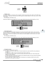
Mixing valve
•
In a mixing system (CONF 4,5), the mixing valve is controlled to maintain the required supply temperature. Set the
parameter (P9) according to the running time of the actuator used.
P9 Actuator Run Time for Mixing Valve
9
8
7
TERMINAL
BLOCK A
Close
Mixing Valve
N
Open
Secondary pump
•
The secondary pump is the circulating pump for the main heating loop. In mono-valent and mono-energetic systems (CONF
1, 2), a secondary pump is only required if a hydraulic separator or buffer tank is used and in this case it is necessary to set
the parameter (P2) to 1. Before the heating is switched off, the pump continues to run for a short time - pump overrun time
(P3) – to distribute the energy through the system.
P2 Secondary Pump Selection (CONF 1,2)
P3 Pump Overrun Time
TERMINAL
BLOCK A
Secondary Pump
4
3
domestic Hot Water (dHW)
•
The System Controller can use the heat pump and boiler (bi-valent systems) to maintain the DHW storage tank at the DHW
setpoint (P10).
P10 DHW setpoint
P11 DHW control differential
P12 DHW supply offset
TERMINAL
BLOCK A
DHW Valve/Pump
6
5
rf receiver box
•
The RF Receiver is connected to the polarity-free terminals 7 and 8. The Room Unit and RF Receiver are already configured
to communicate with each other. If the Room Unit or RF Receiver is replaced, it is necessary to use the RF Binding
procedure.
TERMINAL
BLOCK C
RF Receiver
8
7
dHW electric heater
•
(CONF 1 and 2 only)
If the DHW storage tank contains a thermostatic electric heater, the System Controller can enable it if the heat pump cannot
achieve the required DHW temperature by itself. The system controller waits for a time (P34) after DHW storage heating is
required before enabling this output.


