Test run
Service Manual
158
Test run procedure for Yutaki
SMGB0066 rev.0 - 12/2009
6.2. TEST rUn ProCEdUrE for yUTAKI
Overview
1.
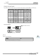
Turning DSW1-2 ON sets the operation mode to be used during a test run.
DIP switch can be set while the power source is ON.
Details
2.
Behavior during Mode Setting
1.
Shifts to this mode when DSW1-2 is turned ON during unit stop.
LED6 turns ON to show that this mode is selected. Note that when DSW1-2 is turned ON when in operation, "40" is
displayed as an incorrect operation and alarm-stop the unit. Recovery from this stop is automatic when DSW1-2 is
turned OFF. Note also that Test Run Mode cannot be performde at the remote controller mode.
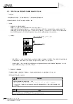
Setting
2.
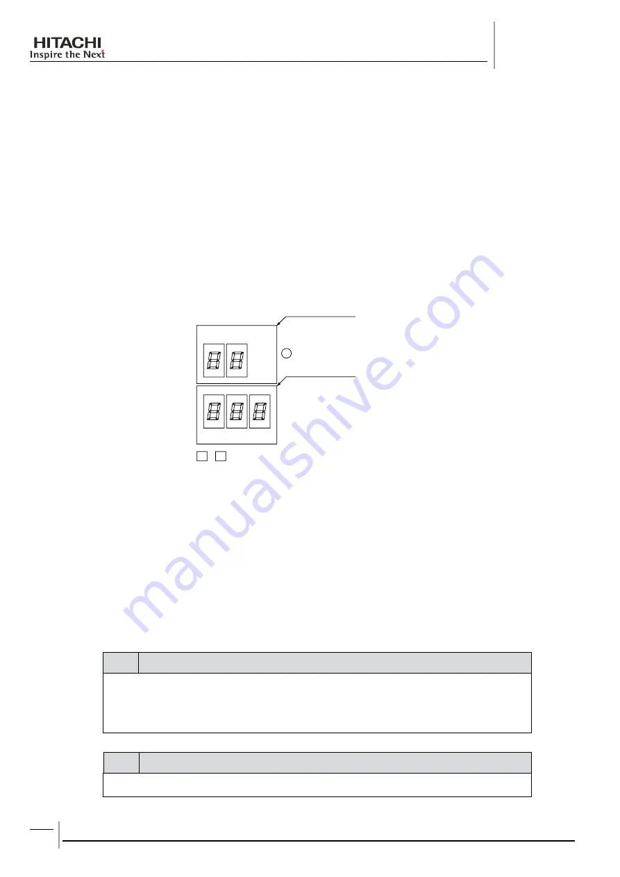
SEG3 SEG4 SEG5
PSW2 PSW1
LED6
SEG1 SEG2
Show code for Test Run Mode details
Show operation status
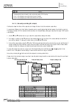
- After shifting this mode, codes of the names of selectable items appear in SEG1.2. The number of items depends
on the product used. Items on the display change each time PSW 2 or 1 is pressed.
- Pressing PSW 1 and 2 together for three seconds or longer activates operation of the displayed item. The SET
display of the item changes from ON --> Flash.
Behaviors in operation
3.
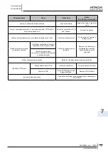
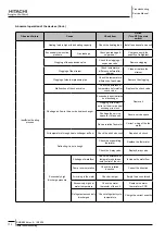
The status display and details of behaviors in each operation mode are described in this section.
LED4 turns ON during operation.
warning
Electrical hazard. Can cause serious injuries.
-
Do not touch any other electrical components while you are setting the switches on the PCB.
-
Do not attach or detach the service access panel when the power source for the unit is ON and the unit is
-
operating.
note
Set all the DIP switches of DSW1 to OFF after completing the test run.
-


