Troubleshooting
Service Manual
180
Troubleshooting procedure
SMGB0066 rev.0 - 12/2009
Alarm code
description
↔
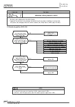
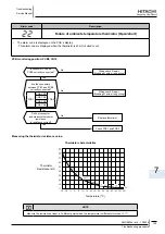
Activation of low pressure control
• The alarm code is displayed on the PCB´s display.
• It appears The electronic control displays the alarm during the operation in heathing or cooling mode.
– This alarm code is displayed when the suction pressure (Ps) is less than 0.1 MPa during 3 seconds.
PCB monitoring position: PCB1, Cn3
note
In case that the low pressure is higher than 2.0 MPa, segment shows 2.0 MPa.
-
In this case, check if the high pressure value "Pd" shown in segment is higher than 1.0 MPa.
-
Is connector CN3 on the
Printed circuit Board (PCB1)
correctly connected?
Wiring Check
(Breaking of wire, wrong
wiring)
No
Yes
Is High Pressure and Low
Presure shown in segment
as "Pd" and "Ps" coincident,
during compressor Stop?
Yes
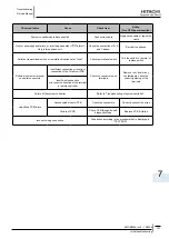
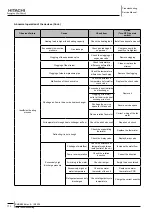
Shortage of Refrigerant/ Gas leakage
No
Clogging of expansion valve
Clogging of low pressure side piping
Not enough air going through heat exchanger
Malfunction of check valve
Air flow is not suficient
Defrost incomplete
Is Low Pressure Sensor
Output character and
High Pressure Sensor display
value "Pd" proper during
compressor Stop?
Yes
Replace PCB
Is the voltage between
VCC12 and GND1 12V on
PCB1?.
Yes
Replace Low Pressure sensor
No
No
Replace PCB


