185
Troubleshooting procedure
SMGB0066 rev.0 - 12/2009
Troubleshooting
Service Manual
7
Alarm code
description
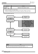
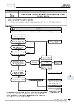
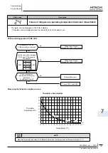
Abnormal transmission between Inverter PCB and Main PCB
• The alarm code is displayed on the PCB´s display.
– This alarm code is displayed when the communication between Main PCB (PCB1) and Inverter (DIP- IPM/ISPM) is
not performed correctly during 30 seconds.
PCB monitoring position: PCB1, Cn8
Is wiring between CN8 of
the PCB1 and CN2,6 on the
Inverter PCB (DIP-IPM/ISPM)
correctly connected?
Wiring check and Repair
(Breaking of wire, wrong wiring)
No
Yes
Check the wiring again ,
PCB1, Inverter PCB (DIP-
IPM/ISPM) are normal.
Power Supply ON after
disconnecting CN8 on PCB1
Is LED 7 (Green) on PCB1
flashing?
No
Yes
Reconnect CN8 on PCB1
No
Failure of Inverter PCB (DIP-IPM/ISPM)
Disconnecting of the wiring between inverter
PCB (DIP-IPM/ISPM) and PCB1
Does LED 7 (Green) flashing
speed become faster than
before?
No
Failure of Inverter PCB (DIP-IPM/ISPM)
Failure of the DC Fan Motor
Yes
Yes
Failure of transmission circuit
on PCB1
Is LED 7 (Green) on PCB1
flashing?
Disconnecting or insufficient contact of the
wiring between Inverter PCB(DIP-IPM/ISPM)
and PCB1


