189
Troubleshooting procedure
SMGB0066 rev.0 - 12/2009
Troubleshooting
Service Manual
7
Alarm code
description
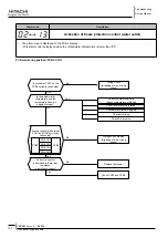
11
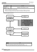
failure of water inlet temperature thermistor
• The alarm code is displayed on the PCB´s display.
– This alarm code is displayed when the water inlet temperature thermistor is short circuited or cut.
PCB monitoring position: PCB2, Cn9
Are the connectors between
PCB1 and PCB2 correctly
connected?
PCB1
CN9-CN1
PCB2
CN5-CN2
CN6-CN3
CN2-CN4
No
Yes
Pull out connector
and measure thermistor
resistance.
Is resistance correct?
No
Replace thermistor
Yes
Is connector CN9 on PCB2
correctly connected?
No
Yes
Wiring check, Repair.
(Breaking of wire, wrong wiring)
Wiring check, Repair.
(Breaking of wire, wrong wiring)
Check PCB1 and PCB2
Measuring the thermistor resistance value:
Thermistor characteristics
Temperature (ºC)
Thermistor
Resistance (k
Ω
)
note
Measure the resistance at least in 2 different points which the temperature is different more than 10 ºC.
-


