Troubleshooting
Service Manual
216
Failure diagnosis method
SMGB0066 rev.0 - 12/2009
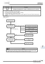
7.3. fAIlUrE dIAGnoSIS METHod
● General check of failure diagnosis.
In the case of no segment indication, unit can not operate.
Is 380-415V (3N~) or 220-
240V (1~) supplied
to the unit?
Check the power
source switch
Yes
No
Is fuse broken?
No
Yes
No
Yes
Is 220-240V supplied to
transformer primary side?
Replace fuse
Yes
No
Is R phase or S
phase failure?
Wiring check
and repair
Wiring check
Connector check
Yes
No
Check the power
source switch
Replace
transformer
Wiring check
Connector check
Is 28.3V in PIN 1-PIN2,
17.6V in PIN3-PIN4,
17.6V in PIN5-PIN6 of the
printed circuit board for
CPU (PCB) connector
CN10A,B?
No
Power Source Circuit
Malfunction
Replace Printed Circuit
Board for CPU (PDB
c
)
No
Yes
Is DIP switch PSW1 PIN4
OFF?
(Compressor Manual Stop)
PSW1 PIN 4 SET ON
Yes
No
Yes
Is voltage 5V in Test
Pins VCC05-GND1 and
VCC05T-GND1 on PCB1?
Is voltage 12V in Test Pins
VCC12-GND1 and
VCC12T-GND1 on PCB1?
Is voltage 24V in Test Pins
VCC24-GND1 and
VCC24N-GND2 on PCB1?
Initialize PCB
If initialization can not
proceed, or segment shows
nothing after initialization,
replace PCB


