Troubleshooting
Service Manual
222
Checking procedure for main parts
SMGB0066 rev.0 - 12/2009
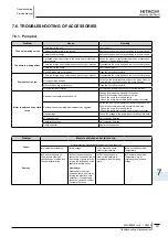
● Checking the transistor module
1. By bP to -UVW or -N to +UVW, no continuity and no variation on voltage drop should appear.
2. By bonding -P to +UVW or +N to -UVW: continuity and variation on voltage drop (nearly 0,405) should be displayed,
and the same value in all cases. Not the same value means that the diode module is damaged.
7.4.3. Checking capacitors CB1 & CB2.
danger
Electrical hazard. Risk of serious injuries or death.
-
Before installing the electrical wiring or before performing a periodical check, turn OFF the main switch of the
-
unit. For safety reasons, be sure that the fan is stopped.
Prevent from touching the capacitors’ terminals. High voltage should be present before discharging them.
-
Turn off the unit and wait for the LED 201 to be off before touching the components.
-
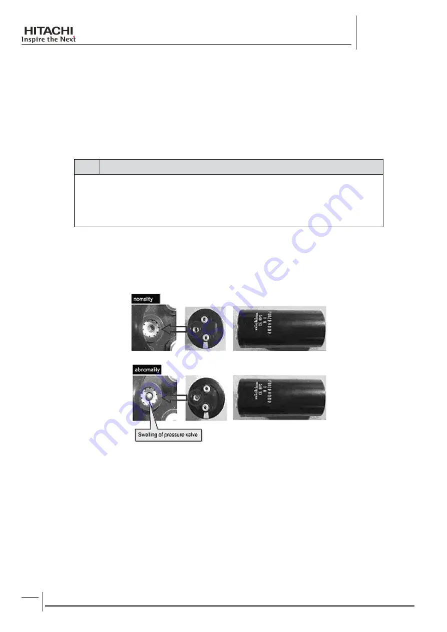
If it’s possible, check the capacitance of each capacitor : 4700μF ± 20% (between 3760μF to 5640μF).
A visual check of the pressure valve of capacitors must be done to ensure it’s integrity:
It is not recommended to check tension.
PN = Power source x √2, PC=CN is nearly equal to PN/2.
R1 & R2:
1) If the value is different:
- Capacitor could be damaged by overload.
- 04 alarm could be displayed if low supply voltage (CN) for ISPM control part is present.
2) R1 = 9.5Ω & R2 = 14.0Ω. If these values are different, the capacitors will be not properly charged.
Resistance between P1 & TB3 = 2kΩ (white resistance in the ISPM).


