Servicing
Service Manual
242
RHUE-(3~6)A(V)HN
SMGB0066 rev.0 - 12/2009
9.1.6. Mounting yutaki fan motor
Remove the service cover according to the section
1.
“Removing service cover” in this chapter.
Remove the air outlet grille according to the section
2.
“Removing air outlet grille” in this chapter.
Remove the upper cover according to the section
3.
“Removing upper cover” in this chapter.
Disassembly the fan blade by removing the cap nuts
4.
and washers fixing the fan blade onto the motor shaft.
If the fan blade get stuck when trying to remove it, use
a puller to disassembly the fan.
Remove the fan motor connector from the PCB3 and
5.
PCB5 at the electrical box.
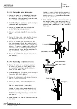
Cut off the cable tie that fixes the lead wire of the
-
fan motor.
Remove the four (4) screws that fix the motor to the
-
motor clamp.
Fix the motor wire with the cable tie or the cord clamp.
6.
If not, it may cause the disconnection of the fan
motor’s lead wire.
In order to avoid cutting edges, mount the rubber bush
7.
at the partition plate when inserting the motor wire
through it. If not, it may cause the disconnection to the
fan motor’s lead wire.
9.1.7. removing the compressor
Remove the service cover and the lower part of the
1.
service panel according to the section “Removing
service cover” and the section “Removing lower part of
service panel and rear panel”. In case that the Yutaki
is installed close to a wall closely, sepparate first the
Yutaki from the wall.
Collect the refrigerant from the liquid stop valve, the
2.
gas stop valve and the check joint at the piping.
Open the sound insulation cover wrapped around the
3.
compressor and remove the terminal box cover at the
compressor fixed by one (1) screw. Disconnect the
compressor wires in the terminal box and remove the
sound insulation cover.
note
Check and take note of each terminal number and
-
indications for its correct connection at the reasembling
process. If wires are connected in incorrect order, it will
lead to a compressor failure.
Remove the rubber cap and the thermistor on the top
4.
of the compressor.
note
When assembling the motor, ensure the cables section
-
directly downwards. Fix the protection tube edge end
downwards to ensure water from keeping inside it
Fix the motor wires onto the motor clamp with a cable tie to
-
prevent them from collisioning the fan blades.
Assembling the fan blade: Insert the skidding protection
-
part of fan boss in accordance with the cutting part of
the motor shaft, and fix the screw after dismounting the
screwed part of the shaft. (Tightening Torque of 20 N.m)
When connecting the motor wire, check to ensure that
-
the colors of the connectors on the PCB3 and PCB5 are
matched with the wires.
Fix the air outlet grille firmly to the shroud.
-
Direction to remove the cover
Sound-proof cover
Cut part
Oil heater
Rubber bush
Partition plate Cord holder
or cable tie
Install DC motor to this
position facing down the trap


