23
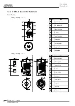
RHUE-(3~6)A(V)HN
SMGB0066 rev.0 - 12/2009
Unit installation
Service Manual
1
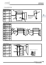
• Air flow guide
Specifications
Model
AG-335A
View from A
Air flow guide
Mounting dimension
Mounting dimension
Quantity
2 per unit
Air discharge direction
Upward (downward), left &
right
Material
Weather proof polypropylene
resin
Color
Gray
Weight
1.9 kg
Accessories
Fixing screw x 4 [M5 (SUS)
x 20]
Installation manual
Installation restriction
“Wind Guard” or “Snow
protection hood” is not
available to install with air
flow guide. (“Guard net”
is available to be installed
together.)
•
Attaching example of air flow guide
- Attach the air flow guide to the air discharge grille with four (4) screws (supplied).
- The fixing holes are located at 4 positions on the grille. (Screw tightening torque 2.4~3.1N.m)
- Do not remove the air discharge grille for air flow guide installation.
warning
Rotating fan blades. Risk of cut. If the air guide is installed without discharge grille, it may cause injury due to
-
rotating fan.
Two windbreak covers installation
Outdoor unit
M5 fixing screw x4
M5 fixing screw x4
(Accessories)
(Accessories)
Air discharge grille
Air flow
Air flow
Air flow guide (*)
Air flow guide (*)
(*) Air flow direction of both air flow guides should be the same
Service space (In case of upward air discharge)
- In case of right and left sides air discharge, enough
space for air discharge is required.
- The downward air discharge is also available. In
such case, install the base under the unit to secure
enough space for air discharge.
- In case of serial units installation, air discharge
should be upward.
Unit
Air flow guide
Passage side

