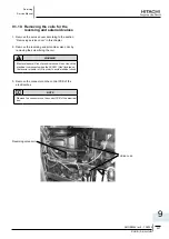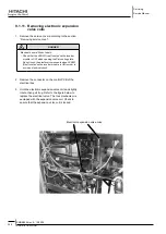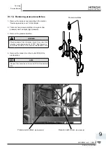
Servicing
Service Manual
252
RHUE-(3~6)A(V)HN
SMGB0066 rev.0 - 12/2009
9.1.16. removing electrical components
danger
Electrical hazard. Risk of death.
-
Check that the LED201 (red) located on the inverter
-
module is OFF when opening the P-mounting plate.
Do not touch the electrical components when LED201
-
(Red) located on the inverter module is ON in order to
avoid an electrical shock.
Remove the service cover according to section
1.
“Removing service cover” in this chapter.
Disconnect all the connectors in the PCB.
-
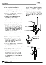
Remove the PCB by sliding four (4) holders in the
-
arrow direction.
Remove the PCB for power distribution of the
-
compressor and the motor.
Removing the relay PCB
2.
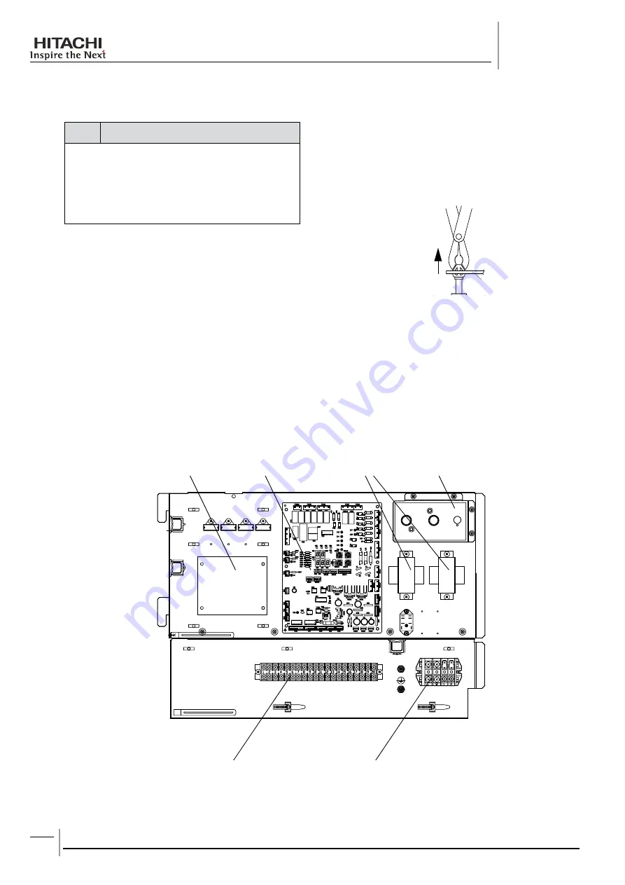
Transformers
Control
Terminal board for power
supply wires
Relay PCB
Terminal board for power
signal wires
Main PCB
Remove the service cover according to the section
-
“Removing Service Cover” in this chapter.
Disconnect all the wires connected to the relay
-
PCB.
Extraction of the PCB from the holders


