43
Accessories hydraulic installation
SMGB0066 rev.0 - 12/2009
Water pipe
installation
Service Manual
2
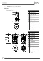
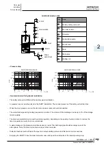
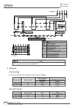
dHWT(200/300)(E/S)-2.5H1E
Return
Input
Mains
water input
Recirculation
H.S.W.
Ref.
Name
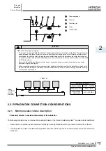
Sanitary safety valve unit
Non-return valve
Circulator
Recirculation pump
Shutoff cock
Drain
Drain valve
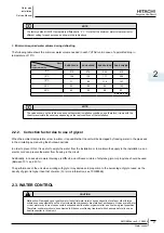
Heating coil
Pressure drop
•
DHWT(200/300)E-2.5H1E
DHWT(200/300)S-2.5H1E
0
1
0.2
0.5
10
100
20
50
200
500
5
10
2
5
C
p
=
m
3
/h
mbar
0
1
0.2
0.5
10
100
20
50
200
500
5
10
2
5
C
p
=
m
3
/h
mbar
General standard for hydraulic installation
•
The safety valve unit will fitted at the sanitary water installation.
-
A pressure reducer must be placed in the DHWT installation. The nominal pressure of the safety unit will be 8 bar.
-
When the main pressure is more than 6 bar a pressure reducer should be installed.
-
The water discharge during heating (expansion) is normal. The volume of this discharge can be up to 3% of the storage
-
tank’s capacity.
The pressure regulator device must be working regularly , depending on the quality of water, in order to remove the
-
lime’s deposits and verify that it is not blockade.
A water leakage in the pressure protection device can exist. The discharge pipe should be always open to the
-
atmosphere, free of frost and in continuous slope to the down side.
Dielectric bushes must be fitted at the input and output sanitary water and at the tank circuit connections.
-
Emptying the DHWT: Close the main inlet water valve and open the relief valve of the security water group.
-


