Electrical wiring
Service Manual
56
Accessories electrical installation
SMGB0066 rev.0 - 12/2009
note
The motor may become damaged by overvoltage.
-
Before applying voltage to the motor, double-check the voltage.
-
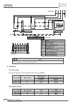
Connect to the mains and connect the SK 602/ SK 622 and SK-C2 tripping unit (observe rating plate data) in
-
accordance with the switching diagrams (Fig. 1).
ToP-S
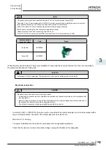
To guarantee protection against dripping water and to ensure strain relief of the cable gland (PG 13.5), a connecting
-
cable with an external diameter of 10 - 12 mm is to be used and assembled as shown in Fig. 2. In addition, the cables
in the vicinity of the cable gland are to be bent into a run-off loop to drain off any dripping water.
Motor protection
¡
Pump
Max. power
consumption
P
1
max
(see rating plate data)
Tripping
reset
Speed switching
TOP-S 25/7
1~230V
P
1
max ≤ 245W
Internal switch off of the motor
main power supply
Auto-reset-once the motor
has cooled down the pump
will automatically switch
back on
Speed adjustment
switch, 3 settings
TOP-S 25/10
1~230V
330W ≤ P
1
max ≤ 400W
WSK and external switch
(SK602/ SK622, C-SK or other
control unit)
Manually at the external
switch box once the motor
has cooled down
Speed adjustment
switch, 3 settings
operation
¡
The system must be filled and vented properly. The pump rotor chamber will vent automatically after a short running period.
Brief dry running will not damage the pump. The pumps wich are equipped with vent screws can be ventilated as follows if
necessary.
Switch off the pump.
1.
Close the shut-off valve on the discharge side.
2.
caution
Risk of scalding.
-
Depending on the fluid temperature and the system presssure, if the vent screw is completely loosened hot
-
liquid or gas should escape or even shoot out at high pressure. Protect all electrical parts against the water
released from the unit.


