81
Supply setpoint calculation
SMGB0066 rev.0 - 12/2009
Controller pack
Service Manual
4
• Example
Bi-Valent System with DHW.
Serial operation with bypass/mixing valve.
DHW controlled by separate pump.
Hydraulic separator or buffer tank.
CONF=5
Bi-Valent Parallel system
P1=2
DHW pump
4.2. SUPPly SETPoInT CAlCUlATIon
Calculation
•
The System Controller uses the “zone of greatest demand” strategy for calculating the supply water temperature required
from the Heat Pump (and/or 3-stage electric heater or boiler).
The system controller recognises three “zones”:
Zone 1:
The normal heating loop controlled directly by the System Controller (direct or mixed depending on the
system configuration).
Zone 2:
The mixed heating loop controlled by the Extension Controller.
DHW zone: The DHW storage tank loading loop.
Each zone can generate a demand to the heat pump (and/or boiler/electric heater) for a particular supply water
temperature
S1:
The supply setpoint water temperature required by the “zone 1” heating loop.
S2:
The supply setpoint water temperature required by the “zone 2” heating loop.
SDHW:
The supply setpoint water temperature required by the DHW loop.
The actual supply setpoint used at any time is the maximum of the three zone supply setpoints.
SSUP = maximum (S1, S2, SDHW)
It is the objective of the system controller to manage the Heat Pump, 3-stage electric heater and boiler appropriately to
control the supply water temperature (TSUP) to this setpoint (SSUP).
Illustration
•
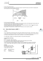
The diagram below shows the three possible “zones” and illustrates the required water temperatures (S1, S2, SDHW) for
each zone, and the resulting overall supply setpoint (SSUP).


