5 WIRING
- 46 -
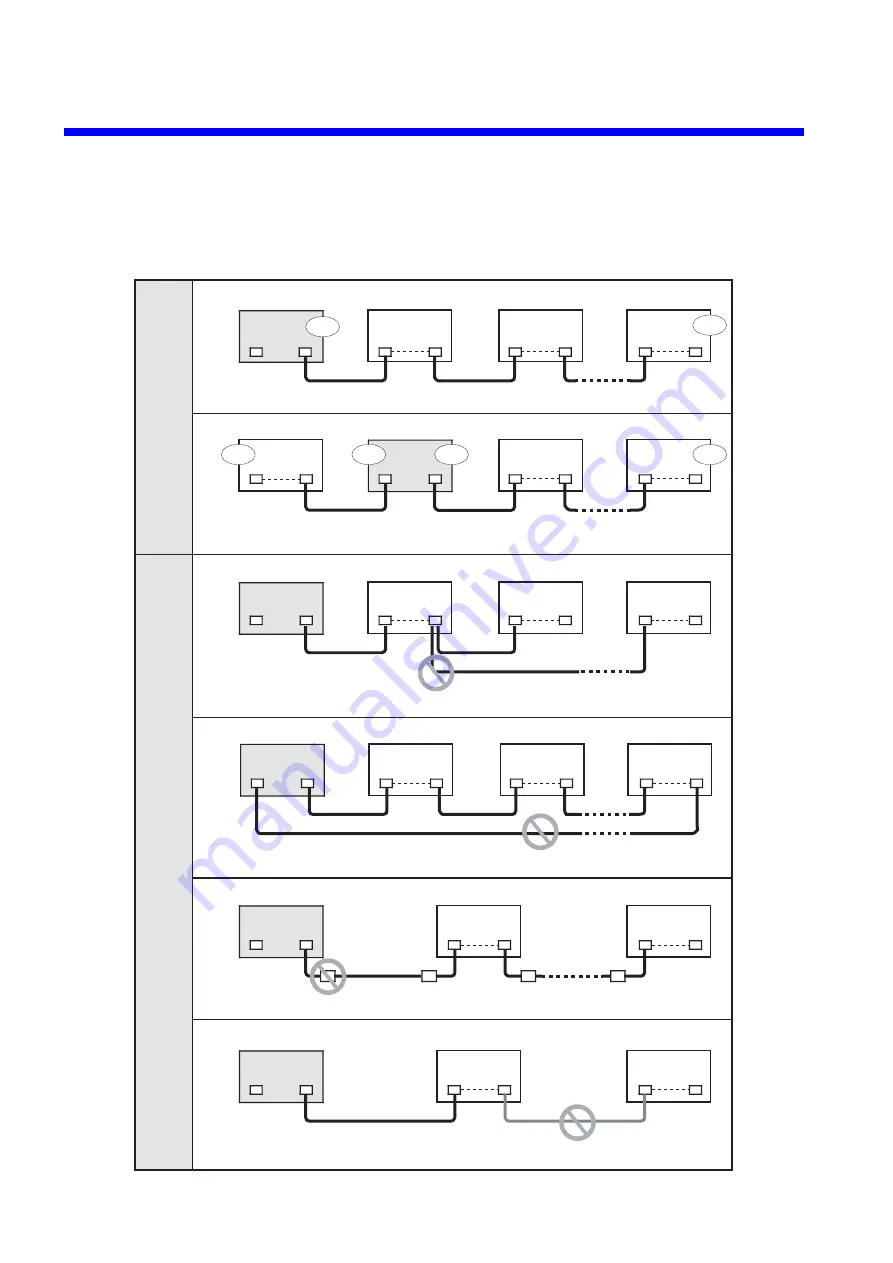
5.6.1 Examples of improper wiring
Improper wiring as shown below causes waveforms on the lines to be distorted, resulting in
communication errors. Make sure that the cables are connected properly.
Do not branch the line.
Do not make a closed loop.
Connect each cable directly to the hardware unit without passing through a terminal block.
Use cables of the same type on the same line.
The CPU module can be installed in any place.
CPU unit
CPU unit
I/O unit
CPU unit
I/O unit
I/O unit
I/O unit
I/O unit
I/O unit
I/O unit
CPU unit
I/O unit
I/O unit
CPU unit
I/O unit
I/O unit
CPU unit
I/O unit
I/O unit
I/O unit
I/O unit
I/O unit
RI/O
2
1
RI/O
2
1
RI/O
2
1
RI/O
Port 1
1
2
RI/O
1
2
RI/O
1
2
RI/O
1
2
RI/O
1
2
RI/O
1
2
RI/O
1
2
RI/O
1
2
RI/O
1
2
RI/O
1
2
RI/O
1
2
RI/O
1
2
RI/O
1
2
RI/O
1
2
TB
TB
TB
TB
RI/O
1
2
RI/O
1
2
Only up to 12 I/O unit can be connected to each communications line. Both ends of the line must be terminated with resistors.
Port 1
Port 2
RI/O
2
1
RI/O
2
1
RI/O
2
1
Terminated
Terminated
Terminated
Terminated
Terminated
Terminated
Proper wiring
Improper wiring
Summary of Contents for S10mini D
Page 1: ......
Page 14: ...THIS PAGE INTENTIONALLY LEFT BLANK ...
Page 19: ...1 BEFORE USE ...
Page 28: ...THIS PAGE INTENTIONALLY LEFT BLANK ...
Page 29: ...2 OVERVIEW ...
Page 34: ...THIS PAGE INTENTIONALLY LEFT BLANK ...
Page 35: ...3 NAMES AND FUNCTIONS OF PARTS ...
Page 45: ...4 INSTALLATION ...
Page 54: ...THIS PAGE INTENTIONALLY LEFT BLANK ...
Page 55: ...5 WIRING ...
Page 68: ...THIS PAGE INTENTIONALLY LEFT BLANK ...
Page 69: ...6 SETTING ...
Page 84: ...THIS PAGE INTENTIONALLY LEFT BLANK ...
Page 85: ...7 OPERATION PROCEDURES ...
Page 91: ...8 EXPLANATION OF OPERATION ...
Page 111: ...9 MAINTENANCE ...
Page 128: ...THIS PAGE INTENTIONALLY LEFT BLANK ...
Page 129: ...10 SPECIFICATIONS ...

