background image

3  INDIVIDUAL SPECIFICATIONS


3-52 

y


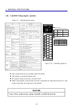
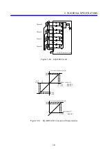
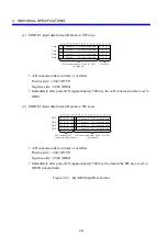
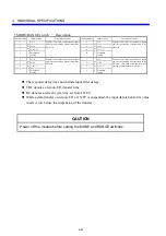
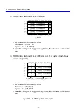
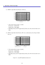
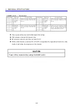
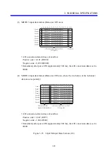
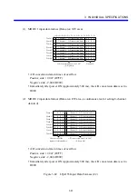
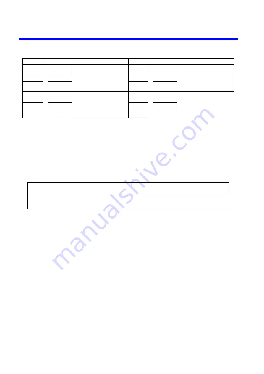
MODE/RANGE switch 

 Description 

Switch setting 

Input voltage 

Description of mode

Switch setting

Input voltage

Description of mode

M
O
D

E

±5 V 

Performs 12-bit A/D conversions on inputs 
and sets the resulting 8-channel data in the 
XW area. 

8

M
O
D

E

3

±5 V

Performs 14-bit A/D conversions on inputs 
and sets the resulting 8-channel data in the 
XW area. 

±10 V 

9

±10 V

1 to 5 V 

A

1 to 5 V

3 Prohibited 

setting 

B Prohibited 

setting

M
O
D

E

±5 V 

Performs 12-bit A/D conversions on inputs 
and sets the resulting 8-channel data in the 
EW area. 

C

M
O
D

E

4

±5 V

Performs 12-bit A/D conversions on inputs 
and sets the resulting 8-channel data in the 
EW area.    (Provided as a mode for use on 
existing S10mini hardware systems.) 

±10 V 

D

±10 V

1 to 5 V 

E

1 to 5 V

7 Prohibited 

setting 

F Prohibited 

setting


z


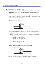
The response delay does not include input filter delays. 

z


TRC denotes a remote I/O transfer time. 

z


RC denotes a refresh cycle time set from J.NET. 

z


While a data transfer on remote I/O or J.NET is suspended, the input data is held at its value 
in effect just before the suspension of the transfer. 


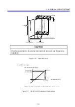
CAUTION 

Power off the module before setting the MODE and RANGE switches. 


Summary of Contents for S10mini LQS070

Page 1: ......

Page 2: ......

Page 3: ...ition August 2009 SME 1 114 E out of print Fifth Edition March 2012 SME 1 114 F All Rights Reserved Copyright 2002 2012 Hitachi Ltd The contents of this publication may be revised without prior notice No part of this publication may be reproduced in any form or by any means without permission in writing from the publisher Printed in Japan BI IC FL MW2007 AI10 ...

Page 4: ...ANGER WARNING or CAUTION This is the safety alert symbol It is used to alert you to potential personal injury hazards Obey all safety messages that follow this symbol to avoid possible injury or death indicates an imminently hazardous situation which if not avoided will result in death or serious injury indicates a potentially hazardous situation which if not avoided could result in death or serio...

Page 5: ...ntenance parts in any manner not described in this manual Such a practice may result in breakdown of this equipment or peripherals injury or even death Hitachi will not be responsible for any accident or failure resulting from such mishandling Read the following safety guidelines carefully and follow them when you conduct maintenance of the machine Before starting maintenance z Maintenance of the ...

Page 6: ...ically inspected z Keep the maintenance area neat and tidy z Always put away parts materials or tools when not in use z Wear an eye protector where anything may fly about z When using sharp objects or cutting tools make sure that no part of your body lies in the path of the blade bit or point z Before finishing your work make sure that all parts removed during maintenance have been installed back ...

Page 7: ...ed If necessary use a measurement tool to ensure that the power is off z Do not touch any uninsulated conductor or surface where so instructed which remains charged for a limited time after the external power supply to the machine is disconnected z When working on a machine which has a grounding terminal make sure that the terminal is properly connected to the facility s ground z When working clos...

Page 8: ...ck z Then call an ambulance z If the victim is unconscious artificial respiration may be necessary A proper method for performing artificial respiration or resuscitation should be learned beforehand If the victim s heart is not beating cardio pulmonary resuscitation should be performed by a trained and qualified person For outbreak of fire z First shut off all the power from the machine using the ...

Page 9: ...therwise appears to be misbehaving switch it off immediately and start problem determination 2 2 CAUTION Statements chapter 1 page 1 7 CAUTION z Before connecting a power supply to a module make sure that it matches the module s rating Connecting a power supply to a module that does not match its rating could result in fires z PCs and LEDs in this product use gallium arsenide GaAs which is designa...

Page 10: ... is used within the rated voltage subsection 4 3 5 page 4 11 CAUTION Install a protective circuit such as a fuse or circuit protector in the external power supply The protective circuit must be one matched to the rating of the power supply 2 3 CAUTION Statements chapter 1 page 1 2 CAUTION To prevent possible failures use the PCs housed in a drip proof enclosure where it may be wetted by moisture c...

Page 11: ...herals have stopped or remain free from adverse effects from such shutdown z Module failures could result in corrupted memory Back up all sensitive data subsection 2 1 8 page 2 10 CAUTION For the LQA050 and LQA150 the SC side is commonly used in the module For the LQA055 and LQA155 the SC side is not commonly used in the module Therefore be sure to use Class D grounding on the external unit side s...

Page 12: ...uld cause damage to the module z The LQZ300 and our product Model LWX000 differ in their connector terminal assignment To avoid damage to the module do not attach a connector wired for the LQZ300 to the LWX000 section 3 25 page 3 40 CAUTION z Use the same power supply for an external power supply and a load power supply Use of different power supplies could result in the module malfunctioning z To...

Page 13: ...1 page 3 66 CAUTION Wire the cable shield to the external terminal block and use Class D grounding collectively section 3 29 page 3 56 section 3 30 page 3 60 section 3 31 page 3 65 section 3 35 page 3 78 section 3 36 page 3 80 CAUTION Power off the module before setting the MODE switch ...

Page 14: ... is short A1S and A1C together then short B1S and B1C together and then ground them all together If it is used with two phase pulse input short the one phase pulse input terminals A2S and A2C together and then ground them together If the stop signal input terminals STOPS and STOPC need not be used short them together and then ground them together z A pulse generator may be connected to the pulse c...

Page 15: ...ter LQP120 CPMS M14 or later E or later LQP510 Ver 2 0 Rev 1 0 or later F or later LQP710 Ver 2 0 Rev 1 0 or later C or later Revisions of programming tool Type Version S10V ladder chart system Ver1 0 Rev3 0 S10mini ladder chart system Ver7 0 Rev6 0 Each module revision in the above table can be found on the bar code label affixed on the top of the module housing It is the rightmost letter of the ...

Page 16: ...assume an input power supply error and request inspection from the power supply facility administrator z Hot replacing a module could lead to damage to hardware or software Be sure to switch modules off before replacing them section 7 2 page 7 6 CAUTION The customer is cautioned not to replace any internal components of the S10mini CPU except for the battery We do not assume responsibility for any...

Page 17: ...than that which was delivered z The malfunction was caused by modifications or repairs made by a vendor other than the vendor that delivered the unit z The malfunction was caused by a relay or other consumable which has passed the end of its service life z The malfunction was caused by a disaster natural or otherwise for which the vendor is not responsible The warranty mentioned here means the war...

Page 18: ...onth Year Remark E The safety guidelines have been reviewed and caution instructions are added for the pulse counter module model LQC000 August 2009 F Additional information is added concerning the service life of the relays contained in certain types of hardware modules March 2012 ...

Page 19: ...This Page Intentionally Left Blank ...

Page 20: ...ller S10mini This manual describes how to handle the S10mini I O module Read this manual thoroughly to properly use this module Trademark Microsoft Windows is a registered trademark of Microsoft Corporation in the United States and or other countries I O Input Output ...

Page 21: ...dule 2 12 2 2 Mounting Design 2 13 2 3 Mount Base 2 18 2 3 1 CPU unit mount base 2 18 2 3 2 I O unit mount base 2 18 2 3 3 Scan type analog input module mount base 2 18 2 4 Combining I O Modules with a CPU or Station Module 2 19 3 INDIVIDUAL SPECIFICATIONS 3 1 3 1 LQX110 Built in signal latches 100 VAC 16 points 3 2 3 2 LQX130 100 VAC 16 points 3 3 3 3 LQX150 200 to 240 VAC inputs 16 points 3 4 3 ...

Page 22: ...nput for the SC side of each channel 3 45 3 28 LQA055 Voltage inputs 8 points different input for the SC side of each channel 3 51 3 29 LQA100 Current inputs 4 points 3 56 3 30 LQA150 Current inputs 8 points common input for the SC side of each channel 3 59 3 31 LQA155 Current inputs 8 points different input for the SC side of each channel 3 64 3 32 LQA200 Resistance temperature detector inputs 4 ...

Page 23: ... If mode 2 is set 4 23 4 6 Handling 8 Channel Analog Input Modules 4 25 4 6 1 MODE1 setting 4 25 4 6 2 MODE2 setting 4 26 4 6 3 MODE3 setting 4 28 4 6 4 MODE4 setting 4 29 4 7 Handling Scan type Analog Input Modules 4 31 4 7 1 Mounting modules 4 31 4 7 2 Wiring modules 4 31 4 7 3 Usage 4 31 4 8 External Dimensions 4 33 5 HANDLING I O DATA ON J NET 5 1 5 1 J NET Settings 5 2 5 2 Data Formats 5 3 6 ...

Page 24: ...it 3 8 Figure 3 15 LQX240 Appearance 3 9 Figure 3 16 LQX240 Circuit 3 9 Figure 3 17 LQX250 Appearance 3 10 Figure 3 18 LQX250 Circuit 3 10 Figure 3 19 LQX300 Appearance 3 11 Figure 3 20 LQX300 Circuit 3 11 Figure 3 21 LQX310 Appearance 3 13 Figure 3 22 LQX310 Circuit 3 13 Figure 3 23 LQX350 Appearance 3 15 Figure 3 24 LQX350 Circuit 3 15 Figure 3 25 Limitation on the Number of Simultaneous ONs for...

Page 25: ... LQY360 Circuit 3 31 Figure 3 52 Limitation on the Number of Simultaneous ONs for the LQY360 3 32 Figure 3 53 LQZ300 Appearance 3 34 Figure 3 54 LQZ300 Circuit 3 35 Figure 3 55 Limitation on the Number of Simultaneous ONs for the LQZ300 3 38 Figure 3 56 LQC000 Appearance 3 39 Figure 3 57 LQC000 Circuit 3 40 Figure 3 58 Pulse Waveform Specifications 3 41 Figure 3 59 LQA000 Appearance 3 42 Figure 3 ...

Page 26: ...igure 3 89 LQA201 A D Conversion Characteristics 3 73 Figure 3 90 LQA201 Input Data Format 3 74 Figure 3 91 LQA500 Appearance 3 75 Figure 3 92 LQA500 Circuit 3 76 Figure 3 93 LQA500 D A Conversion Characteristics 3 76 Figure 3 94 LQA500 Output Data Format 3 77 Figure 3 95 LQA600 Appearance 3 78 Figure 3 96 LQA600 Circuit 3 79 Figure 3 97 LQA600 D A Conversion Characteristics 3 79 Figure 3 98 LQA60...

Page 27: ...ut Module 4 6 Figure 4 5 Connecting a Resistance to a DC Input Module 4 6 Figure 4 6 Surge Absorbers Circuit 4 7 Figure 4 7 LQY160 and LQY170 Contact Output Actions 4 10 Figure 4 8 Example of a Prohibited Connection of the LQY160 and LQY170 4 10 Figure 4 9 Operation Flowchart 4 18 Figure 4 10 Sample Program 4 19 Figure 4 11 Allocation Example 4 24 Figure 7 1 LQV000 Appearance 7 3 Figure 7 2 Troubl...

Page 28: ... 12 Table 3 12 LQX310 Specifications 3 13 Table 3 13 LQX310 Address Assignments 3 14 Table 3 14 LQX350 Specifications 3 15 Table 3 15 LQX350 Address Assignments 3 16 Table 3 16 LQX360 Specifications 3 17 Table 3 17 LQX360 Address Assignments 3 18 Table 3 18 LQY100 Specifications 3 19 Table 3 19 LQY140 Specifications 3 20 Table 3 20 LQY150 Specifications 3 21 Table 3 21 LQY160 Specifications 3 22 T...

Page 29: ...e 3 49 LQA800 and LQA810 Specifications 3 84 Table 4 1 I O Module Fuse Ratings 4 11 Table 4 2 Status of the LQC000 Immediately after the I O Unit is Switched ON 4 20 Table 4 3 Status of the LQC000 Following a Suspension of a Remote I O Transfer 4 20 Table 4 4 Status of the LQC000 Installed in the I O Unit Upon OFF to ON Transitions in CPU Unit Power 4 21 Table 4 5 Registration Numbers and Allocate...

Page 30: ...1 BEFORE USE ...

Page 31: ...g your system within its warranted limits of performance it is recommended to take fail safe and other system precautions by allowing for the failure rate and failure mode that are anticipated for our product to defend against from personal injury fires and other extended damages that may result from the behavior of our product 2 The PCs is not of fireproof dustproof and waterproof construction Wh...

Page 32: ... LQV100 85 to 132 VAC 85 to 132 VDC LQV020 20 4 to 28 8 VDC LQV200 170 to 264 VAC Temperature Operating 0 to 55ºC Storage 20 to 75ºC Temperature change rate 10ºC h or lower Relative humidity Operating 30 to 90 RH Storage 10 to 90 RH non condensing Vibration resistance Compliant with JIS C0040 Frequency 10 to 150 Hz Acceleration 10 m s2 8 minute sweep in each of the X Y Z axis directions 20 sweep c...

Page 33: ...he grounding point for the Programmable Controller be at least 15 m away from an AC panel grounding point It is the best that the grounding wire be welded to the steel frame of a building In case when the aforesaid is impossible bury the grounding rod in earth Class D grounding is defined in the Technical Standard for Electrical Facilities of Japan This standard states that the grounding resistanc...

Page 34: ...e entire module in which a defective part is included For details on parts replacement contact your Hitachi maintenance personnel 9 Module insertion removal Power must be turned off while a module is inserted or removed Insertion or removal of a module when power is ON may cause damage to the module or electric shock 10 Equipment addition If the peripheral equipment is added or altered conduct an ...

Page 35: ...ING z Build an emergency stop circuit interlock circuits and so forth outside this product If these circuits were built inside the product its failures could result in damage to hardware or in accidents z Limit the I O current through an I O module to the maximum allowable current rating or below Overcurrent flow through an I O module could cause damage to its internal components resulting in acci...

Page 36: ...ceivers cell phones and like devices near this system These devices could impart noises to the system causing it to malfunction CAUTION Do not install hardwire handle and make internal modifications to the product except to such extent as covered in this manual We do not assume responsibility for any consequential damages to our equipment and peripheral devices and for personal injury CAUTION z In...

Page 37: ...This Page Intentionally Left Blank ...

Page 38: ...2 KINDS AND SPECIFICATIONS OF I O MODULES ...

Page 39: ... LQX201 LQX220 LQX240 Input format DC input sink source DC input sink source DC input sink source DC input sink source Number of inputs 16 inputs 16 inputs 16 inputs 16 inputs Number of commons 8 common 8 common 8 common 8 common Insulation method Photocoupler Photocoupler Photocoupler Photocoupler Rated input voltage 12 to 24 VDC 12 to 24 VDC 48 VDC 100 VDC Rated input current 3 4 mA 12 VDC to 7 ...

Page 40: ...ON voltage current 9 VDC 1 4 mA 9 VDC 1 4 mA Maximum OFF voltage current 3 VDC 0 3 mA 3 VDC 0 3 mA Input impedance Approx 5 6 kΩ Approx 5 6 kΩ Response time OFF ON 10 ms or less 10 ms or less ON OFF 10 ms or less 10 ms or less Internal current dissipation 150 mA or less 170 mA or less External wiring connection method 40 point connector 34 point connector 40 point connector 34 point connector Oper...

Page 41: ...e analog input module mount base Mountable Type LQX210 LQX211 LQX250 Input format DC input sink source DC input sink source DC input sink source Number of inputs 16 inputs 16 inputs 16 inputs Number of commons 8 common 8 common 8 common Insulation method Photocoupler Photocoupler Photocoupler Rated input voltage 24 VDC 24 VDC 100 VDC Rated input current Approx 10 mA Approx 10 mA Approx 5 mA Operat...

Page 42: ...20 g Combining mount base CPU unit mount base Mountable I O unit mount base Mountable Scan type analog input module mount base Mountable Type LQY150 LQY160 Output format Contact output Contact output Number of outputs 8 outputs b contacts 8 6 outputs a contacts 2 c contacts 4 Number of commons None All points Independent None All points Independent Insulation method Relay Relay Rated output voltag...

Page 43: ...I O unit mount base Mountable Scan type analog input module mount base Mountable Type LQY200 Output format Transistor output sink Number of outputs 16 outputs Number of commons 16 common Insulation method Photocoupler Rated output voltage 12 to 24 VDC Maximum output current 0 3 A output Response time OFF ON 0 2 ms or less ON OFF 0 3 ms or less resistive load Internal current dissipation 120 mA or ...

Page 44: ...nt base CPU unit mount base Mountable I O unit mount base Mountable Scan type analog input module mount base Mountable 2 1 6 Digital input module Type LQZ300 Input section Output section Input format DC input sink source Output format Transistor output sink Number of inputs 32 inputs Number of outputs 32 outputs Number of commons 32 common Number of commons 32 common Insulation method Photocoupler...

Page 45: ... 10 2 to 26 4 VDC Rated input current Approx 7 mA 12 VDC approx 14 mA 24 VDC ON voltage current 10 VDC or more 5 3 mA or more OFF voltage current 3 mADC or less 0 8 mA or less Output Compare result output format Count value compare value coincident output is latch Rated output voltage 12 to 24 VDC Output voltage range 10 to 28 VDC Maximum output current 0 3 A Response time ON OFF delay 1 ms or les...

Page 46: ...0 g 230 g Combining mount base CPU unit mount base Mountable I O unit mount base Mountable Scan type analog input module mount base Mountable Type LQA200 LQA201 Input method Resistance temperature detector Pt100 Ω JPt100 Ω Resistance temperature detector Pt100 Ω JPt100 Ω Input range 100 to 100ºC 200 to 350ºC 200 to 500ºC 50 to 150ºC 200 to 100ºC 100 to 350ºC RANGE switch setting 0 1 2 0 1 2 Mode 1...

Page 47: ...nsfer 5 12ms RC J NET transfer 5 12 ms TRC remote I O transfer 5 12ms RC J NET transfer MODE 2 5 12 ms 8 TRC remote I O transfer 5 12ms RC J NET transfer 5 12 ms 8 TRC remote I O transfer 5 12ms RC J NET transfer MODE 3 5 12 ms TRC remote I O transfer 5 12ms RC J NET transfer 5 12 ms TRC remote I O transfer 5 12ms RC J NET transfer MODE 4 5 12 ms 4 TRC remote I O transfer 5 12ms RC J NET transfer ...

Page 48: ...TRC 4 ms TRC ON OFF 4 ms 4TRC 4 ms 4TRC Internal current dissipation Module REV A 500 mA or less 500 mA or less Module REV B 530 mA or less 530 mA or less External wiring connection method 18 point terminal block 18 point terminal block Mass 240 g 240 g Combining mount base CPU unit mount base Mountable I O unit mount base Mountable Scan type analog input module mount base Mountable Type LQA610 Ou...

Page 49: ...ntable I O unit mount base Not mountable Scan type analog input module mount base Mountable 2 1 11 Scan type commonly insulated analog input module Type LQA800 A D conversion module LQA810 scanner module Input method Voltage input Input range E 5 VDC Maximum input voltage E 15 VDC Maximum number of input channels 28 channels Insulation method Photocouplers common to all channels Channel to channel...

Page 50: ...Table 2 1 Module Current Dissipation Values 1 2 Description Type Current dissipation CPU module LQP 1 500 mA or less Station module LQS000 150 mA or less LQS020 700 mA or less Digital input module LQX110 110 mA or less LQX130 70 mA or less LQX150 110 mA or less LQX151 110 mA or less LQX200 80 mA or less LQX201 80 mA or less LQX210 110 mA or less LQX211 170 mA or less LQX220 110 mA or less LQX240 1...

Page 51: ... later 580 mA or less LQA201 Module REV A 500 mA or less Module REV B or later 580 mA or less Analog output module LQA500 Module REV A 500 mA or less Module REV B or later 530 mA or less LQA600 Module REV A 500 mA or less Module REV B or later 530 mA or less LQA610 Module REV A 500 mA or less Module REV B or later 530 mA or less Scan type separately insulated analog input module A D conversion mod...

Page 52: ... at an ambient temperature of 55 LQV000 LQV100 LQV020 Derating is required LQV200 Derating is not required Figure 2 1 Power Supply Module Maximum Output Current Ratings CAUTION Heat dissipation could cause fires or unit failures to occur When the ambient temperature of a unit using LQV000 LQV100 or LQV020 exceeds 48 C limit the maximum output current of the power supply module The maximum output c...

Page 53: ...s that mountable in the scan type analog input module mount base Digital input module LQX110 8 8 8 LQX130 8 8 8 LQX150 8 8 8 LQX151 8 8 8 LQX200 8 8 8 LQX201 8 8 8 LQX210 8 8 8 LQX211 8 8 8 LQX220 8 8 8 LQX240 8 8 8 LQX250 8 8 8 LQX300 8 8 8 LQX310 8 8 8 LQX350 8 8 8 LQX360 8 8 8 Digital output module LQY100 7 8 8 LQY140 8 8 8 LQY150 6 8 8 LQY160 8 8 8 LQY170 8 8 8 LQY200 8 8 8 LQY300 8 8 8 LQY310...

Page 54: ...log input module LQA000 8 8 8 LQA050 8 8 8 LQA055 8 8 8 LQA100 8 8 8 LQA150 8 8 8 LQA155 8 8 8 LQA200 8 8 8 LQA201 8 8 8 Analog output module LQA500 8 8 8 LQA600 8 8 8 LQA610 8 8 8 Scan type separately insulated analog input module A D conversion module LQA301 Not mountable Not mountable 1 Scanner module LQA310 Not mountable Not mountable 7 Scan type commonly insulated analog input module A D conv...

Page 55: ...LQA8 Four slot mount base HSC 1040 Eight slot mount base HSC 1080 2 3 2 I O unit mount base Name Type Required modules Optional modules Two slot mount base HSC 1021 y Power supply module y Remote I O station module J STATION or D Station module I O modules except for the LQA3 and LQA8 Four slot mount base HSC 1041 Eight slot mount base HSC 1081 2 3 3 Scan type analog input module mount base Name T...

Page 56: ... Supported Combinations of I O Modules with CPU and Station Modules Combinable nc Not combinable Module type CPU module Remote I O station module J STATION module D Station module LQX110 LQX130 LQX150 LQX151 LQX200 LQX201 LQX210 LQX211 LQX220 LQX240 LQX250 LQX300 LQX310 LQX350 LQX360 LQY100 LQY140 LQY150 LQY160 LQY170 LQY200 LQY300 LQY310 LQY350 LQY360 LQZ300 LQC000 LQA000 LQA050 LQA055 LQA100 LQA...

Page 57: ...This Page Intentionally Left Blank ...

Page 58: ...3 INDIVIDUAL SPECIFICATIONS ...

Page 59: ... coil of the address to reset Internal current dissipation 110 mA or less Number of commons 8 inputs common Dielectric voltage 1 500 VAC 1 minute between external terminals in a batch and ground External wiring Connection method 18 point terminal block connector screw M3 Compatible wire 0 3 to 1 25 mm2 Tightening torque Approx 6 to 8 N m Allowable wiring length 200 m Operation indication LED indic...

Page 60: ...5 mm2 Tightening torque Approx 6 to 8 N m Allowable wiring length 200 m Operation indication LED indication lit when ON color green Mass 210 g If a reed relay is used as an input contact the rush current through the module could cause the contact to fuse To avoid this use a reed relay with an adequately large switching capacity Fuse Contact 100 to 120 VAC A1 B1 B5 0 7 C0 8 F A5 A9 C1 B9 Input indi...

Page 61: ...ernal wiring Connection method 18 point terminal block connector screw M3 Compatible wire 0 5 to 2 0 mm2 Tightening torque Approx 6 to 8 N m Allowable wiring length 200 m or less Operation indication LED indication lit when ON color green Mass 240 g A1 0 F B9 A9 COM Control circuit Input indication LED Figure 3 6 LQX150 Circuit CAUTION z Use the input voltage within the voltage rating Applying vol...

Page 62: ...y External wiring Connection method 18 point terminal block connector screw M3 Compatible wire 0 5 to 2 0 mm2 Tightening torque Approx 6 to 8 N m Allowable wiring length 200 m or less Operation indication LED indication lit when ON color green Mass 240 g TRC Remote I O transfer time A1 0 F B9 A9 COM Control circuit Input indication LED Figure 3 8 LQX151 Circuit CAUTION z Use the input voltage with...

Page 63: ... common Dielectric voltage 1 500 VAC 1 minute between external terminals in a batch and ground External wiring Connection method 18 point terminal block connector screw M3 Compatible wire 0 3 to 1 25 mm2 Tightening torque Approx 6 to 8 N m Allowable wiring length 200 m Operation indication LED indication lit when ON color green Mass 210 g Fuse Contact 12 to 24 VDC A1 B1 B5 0 7 C0 8 F A5 A9 C1 B9 I...

Page 64: ...less Number of commons 8 inputs common Dielectric voltage 1 500 VAC 1 minute between external terminals in a batch and ground External wiring Connection method 18 point terminal block connector screw M3 Compatible wire 0 3 to 1 25 mm2 Tightening torque Approx 6 to 8 N m Allowable wiring length 200 m Operation indication LED indication lit when ON color green Mass 230 g TRC Remote I O transfer time...

Page 65: ...nputs common Dielectric voltage 1 500 VAC 1 minute between external terminals in a batch and ground External wiring Connection method 18 point terminal block connector screw M3 Compatible wire 0 3 to 1 25 mm2 Tightening torque Approx 6 to 8 N m Allowable wiring length 200 m Operation indication LED indication lit when ON color green Mass 230 g Fuse Contact 48 VDC A1 B1 B5 0 7 C0 8 F A5 A9 C1 B9 In...

Page 66: ...s common Dielectric voltage 1 500 VAC 1 minute between external terminals in a batch and ground External wiring Connection method 18 point terminal block connector screw M3 Compatible wire 0 3 to 1 25 mm2 Tightening torque Approx 6 to 8 N m Allowable wiring length 200 m Operation indication LED indication lit when ON color green Mass 230 g Fuse Contact 100 VDC A1 B1 B5 0 7 C0 8 F A5 A9 C1 B9 Input...

Page 67: ...10 mA or less Number of commons 8 inputs common Dielectric voltage 1 500 VAC 1 minute between external terminals in a batch and ground External wiring Connection method 18 point terminal block connector screw M3 Compatible wire 0 3 to 1 25 mm2 Tightening torque Approx 6 to 8 N m Allowable wiring length 200 m Operation indication LED indication lit when ON color green Mass 230 g TRC Remote I O tran...

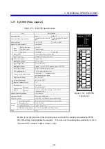
Page 68: ...ernal terminals in a batch and ground External wiring Connection method 40 point connector Model FCN36 manufactured by Fujitsu Devices Inc Compatible wire 200 m or less Operation indication LED indication lit when ON color green Selection indication by SW1 Mass 150 g CN1B20 CN1A5 Contact 12 to 24 VDC Fuse CN1B1 Input indication LED CN1B2 Input indication LED selector switch 000 01F COM COM SW1 Con...

Page 69: ...00A CN1A20 X010 CN1A10 X01A CN1B19 X001 CN1B9 X00B CN1A19 X011 CN1A9 X01B CN1B18 X002 CN1B8 X00C CN1A18 X012 CN1A8 X01C CN1B17 X003 CN1B7 X00D CN1A17 X013 CN1A7 X01D CN1B16 X004 CN1B6 X00E CN1A16 X014 CN1A6 X01E CN1B15 X005 CN1B5 X00F CN1A15 X015 CN1A5 X01F CN1B14 X006 CN1B4 Reserved CN1A14 X016 CN1A4 Reserved CN1B13 X007 CN1B3 Reserved CN1A13 X017 CN1A3 Reserved CN1B12 X008 CN1B2 COM CN1A12 X018 ...

Page 70: ...etween external terminals in a batch and ground External wiring Connection method 34 point connector Model FRC3 manufactured by DDK Ltd Compatible wire 200 m or less Operation indication LED indication lit when ON color green Selection indication by SW1 Mass 150 g CN1 34 CN1 3 Contact 12 to 24 VDC Fuse CN1 2 Input indication LED Input indication LED selector switch 000 01F COM SW1 Control circuit ...

Page 71: ...ess Pin No Address CN1 34 X000 CN1 26 X008 CN1 18 X010 CN1 10 X018 CN1 33 X001 CN1 25 X009 CN1 17 X011 CN1 9 X019 CN1 32 X002 CN1 24 X00A CN1 16 X012 CN1 8 X01A CN1 31 X003 CN1 23 X00B CN1 15 X013 CN1 7 X01B CN1 30 X004 CN1 22 X00C CN1 14 X014 CN1 6 X01C CN1 29 X005 CN1 21 X00D CN1 13 X015 CN1 5 X01D CN1 28 X006 CN1 20 X00E CN1 12 X016 CN1 4 X01E CN1 27 X007 CN1 19 X00F CN1 11 X017 CN1 3 X01F CN1 ...

Page 72: ...ernal wiring Connection method 40 point connector Model FCN36 manufactured by Fujitsu Devices Inc Compatible wire 200 m or less Operation indication LED indication lit when ON color green Selection indication by SW1 and SW2 Mass 170 g Fuse Contact 12 to 24 VDC CN2B20 020 03F COM2 CN2A5 CN2B2 CN2B1 COM2 CN1B20 000 01F COM1 Input indication LED CN1A5 CN1B2 CN1B1 COM1 Input indication LED selector sw...

Page 73: ...CN2B10 X02A CN2A10 X03A CN1B9 X00B CN1A9 X01B CN2B9 X02B CN2A9 X03B CN1B8 X00C CN1A8 X01C CN2B8 X02C CN2A8 X03C CN1B7 X00D CN1A7 X01D CN2B7 X02D CN2A7 X03D CN1B6 X00E CN1A6 X01E CN2B6 X02E CN2A6 X03E CN1B5 X00F CN1A5 X01F CN2B5 X02F CN2A5 X03F CN1B4 Reserved CN1A4 Reserved CN2B4 Reserved CN2A4 Reserved CN1B3 Reserved CN1A3 Reserved CN2B3 Reserved CN2A3 Reserved CN1B2 COM1 CN1A2 Reserved CN2B2 COM2...

Page 74: ... and ground External wiring Connection method 34 point connector Model FRC3 manufactured by DDK Ltd Compatible wire 200 m or less Operation indication LED indication lit when ON color green Selection indication by SW1 and SW2 Mass 170 g Fuse Contact 12 to 24 VDC CN2 34 020 03F COM2 CN2 3 CN2 2 CN1 34 000 01F COM1 Input indication LED CN1 3 CN1 2 Input indication LED selector switch SW1 SW2 Control...

Page 75: ... CN2 10 X038 CN1 25 X009 CN1 9 X019 CN2 25 X029 CN2 9 X039 CN1 24 X00A CN1 8 X01A CN2 24 X02A CN2 8 X03A CN1 23 X00B CN1 7 X01B CN2 23 X02B CN2 7 X03B CN1 22 X00C CN1 6 X01C CN2 22 X02C CN2 6 X03C CN1 21 X00D CN1 5 X01D CN2 21 X02D CN2 5 X03D CN1 20 X00E CN1 4 X01E CN2 20 X02E CN2 4 X03E CN1 19 X00F CN1 3 X01F CN2 19 X02F CN2 3 X03F CN1 2 COM1 CN1 1 Reserved CN2 2 COM2 CN2 1 Reserved Q Limitation ...

Page 76: ...ion frequency of 1 800 cycles per hour normal temperature and normal humidity Internal current dissipation 780 mA or less Number of commons 8 outputs common Dielectric voltage 1 500 VAC 1 minute between external terminals in a batch and ground External wiring Connection method 18 point terminal block connector screw M3 Compatible wire 0 3 to 1 25 mm2 Tightening torque Approx 6 to 8 N m Allowable w...

Page 77: ...1 800 cycles per hour normal temperature and normal humidity Internal current dissipation 400 mA or less Number of commons One input common independent common Dielectric voltage 1 500 VAC 1 minute between external terminals in a batch and ground External wiring Connection method 18 point terminal block connector screw M3 Compatible wire 0 3 to 1 25 mm2 Tightening torque Approx 6 to 8 N m Allowable...

Page 78: ...emperature and normal humidity Internal current dissipation 800 mA or less Number of commons One input common independent common Dielectric voltage 1 500 VAC 1 minute between external terminals in a batch and ground External wiring Connection method 18 point terminal block connector screw M3 Compatible wire 0 3 to 1 25 mm2 Tightening torque Approx 6 to 8 N m Allowable wiring length 200 m Operation...

Page 79: ... mA Dielectric voltage 1 500 VAC 1 minute between external terminals in a batch and ground External wiring Connection method 18 point terminal block connector screw M3 Compatible wire 0 3 to 1 25 mm2 Tightening torque Approx 6 to 8 N m Allowable wiring length 200 m Operation indication LED indication lit when a contact ON color green Mass 250 g The address assignments are shown below 0 1 2 3 4 5 6...

Page 80: ...C 1 minute between the primary and the secondary External wiring Connection method 18 point terminal block connector screw M3 Compatible wire 0 3 to 2 0 mm2 Tightening torque Approx 6 to 8 N m Allowable wiring length 200 m or less Operation indication LED indication lit when ON color green Mass 250 g or less The address assignments are shown below 0 1 2 3 4 5 6 7 8 9 A B C D E F MSB LSB 無効 0 a5 OF...

Page 81: ...and ground External wiring Connection method 18 point terminal block connector screw M3 Compatible wire 0 3 to 1 25 mm2 Tightening torque Approx 6 to 8 N m Allowable wiring length 200 m Operation indication LED indication lit when ON color green Mass 210 g 1 Use the same power supply for an external power supply and a load power supply 2 Use of a load could result in a delay by up to around 1 s L ...

Page 82: ...actured by Fujitsu Devices Inc Allowable wiring length 200 m or less Operation indication LED indication lit when ON color green Selection indication by SW1 Mass 150 g 1 Use the same power supply for an external power supply and a load power supply 2 Use of a load could result in a delay by up to around 1 s 3 If using a pressure contact connector FCN367J070 AU F set it to 1 0A common L CN1B2 V Loa...

Page 83: ... on the number of simultaneous ONs 1 Use the same power supply for the external power supply to the V terminal and for the load power supply Use of different power supplies could result in the module malfunctioning 2 The operating ambient temperature and the load current pose the limitation shown below on the number of simultaneous ONs for the LQY300 Attempted use past this limitation will degrade...

Page 84: ...onnection method 34 point connector Model FRC3 manufactured by DDK Ltd Allowable wiring length 200 m or less Operation indication LED indication lit when ON color green Selection indication by SW1 Mass 150 g 1 Use the same power supply for an external power supply and a load power supply 2 Use of a load could result in a delay by up to around 1 s L CN1 2 V Load CN1 1 COM L CN1 34 000 CN1 3 01F Out...

Page 85: ...ultaneous ONs 1 Use the same power supply for the external power supply to the V terminal and for the load power supply Use of different power supplies could result in the module malfunctioning 2 The operating ambient temperature and the load current pose the limitation shown below on the number of simultaneous ONs for the LQY310 Attempted use past this limitation will degrade the product life Num...

Page 86: ... LED indication lit when ON color green Selection indication by SW1 and SW2 Mass 170 g 1 Use the same power supply for an external power supply and a load power supply 2 Use of a load could result in a delay by up to around 1 s 3 If using a pressure contact connector FCN367J040 AU F set it to 1 0A common L CN1B2 V1 Load Fuse 2 12 24 VDC 1 Output indication LED CN1B1 V1 CN1A2 COM1 CN1A1 COM1 L CN1B...

Page 87: ...N1A5 Y01F CN2B5 Y02F CN2A5 Y03F CN1B4 Reserved CN1A4 Reserved CN2B4 Reserved CN2A4 Reserved CN1B3 Reserved CN1A3 Reserved CN2B3 Reserved CN2A3 Reserved CN1B2 V1 CN1A2 COM1 CN2B2 V2 CN2A2 COM2 CN1B1 V1 CN1A1 COM1 CN2B1 V2 CN2A1 COM2 Q Limitation on the number of simultaneous ONs 1 Use the same power supply for the external power supply to the V terminal and for the load power supply Use of differen...

Page 88: ... wiring length 200 m or less Operation indication LED indication lit when ON color green Selection indication by SW1 and SW2 Mass 170 g 1 Use the same power supply for an external power supply and a load power supply 2 Use of a load could result in a delay by up to around 1 s L CN1 2 V1 Load Fuse 2 12 24 VDC 1 Output indication LED CN1 1 COM1 L CN1 34 000 CN1 3 01F Output indication LED selector s...

Page 89: ...D CN2 21 Y02D CN2 5 Y03D CN1 20 Y00E CN1 4 Y01E CN2 20 Y02E CN2 4 Y03E CN1 19 Y00F CN1 3 Y01F CN2 19 Y02F CN2 3 Y03F CN1 2 V1 CN1 1 COM1 CN2 2 V2 CN2 1 COM2 Q Limitation on the number of simultaneous ONs 1 Use the same power supply for the external power supply to the V terminal and for the load power supply Use of different power supplies could result in the module malfunctioning 2 The operating ...

Page 90: ... which this module is installed to FREE The FIX setting would cause the module to malfunction For how to set mounting base partitions refer to S10mini CPU Manual number SME 1 100 Table 3 33 Input Specifications Item Specification Number of inputs 32 inputs Insulation method Photocoupler insulation Rated input voltage 12 to 24 VDC Rated input current 4 1 mA 24 VDC 2 1 mA 12 VDC Limitation on the nu...

Page 91: ...he same power supply for an external power supply and a load power supply 12 24 VDC LQZ300 D IN OUT 3 2 1 0 7 6 5 4 B A 9 8 F E D C SW1 IN U IN L Operation indication LED selector switches SW1 SW2 To display input data on the LED set the switches as specified in the table below SW1 Display data SW2 Left side X000 to 00F Left side X010 to 01F Right side Left side Left side Right side Y020 to 02F Ri...

Page 92: ...B20 020 OUTPUTB5 02F OUTPUTB2 V OUTPUTB1 V Fuse 4 12 24 VDC 1 Load SW3 Assigned address setup switch 01F INPUTA5 INPUTA20 010 L L OUTPUTA20 030 OUTPUTA5 03F 12 24 VDC 2 Control circuit Figure 3 54 LQZ300 Circuit 1 While the power connection is shown to be a common above it can also be used as a common 2 Use the same power supply for the external power supply for the output circuit and for the load...

Page 93: ...NPUTB2 COM1 INPUTA2 Reserved OUTPUTB2 V OUTPUTA2 COM2 INPUTB1 COM1 INPUTA1 Reserved OUTPUTB1 V OUTPUTA1 COM2 Q To set SW3 to 1 assuming a starting address of 000 Table 3 35 LQZ300 Address Assignments 2 Pin No Address Pin No Address Pin No Address Pin No Address INPUTB20 X020 INPUTA20 X030 OUTPUTB20 Y000 OUTPUTA20 Y010 INPUTB19 X021 INPUTA19 X031 OUTPUTB19 Y001 OUTPUTA19 Y011 INPUTB18 X022 INPUTA18...

Page 94: ...00A OUTPUTA10 Y01A INPUTB9 X00B INPUTA9 X01B OUTPUTB9 Y00B OUTPUTA9 Y01B INPUTB8 X00C INPUTA8 X01C OUTPUTB8 Y00C OUTPUTA8 Y01C INPUTB7 X00D INPUTA7 X01D OUTPUTB7 Y00D OUTPUTA7 Y01D INPUTB6 X00E INPUTA6 X01E OUTPUTB6 Y00E OUTPUTA6 Y01E INPUTB5 X00F INPUTA5 X01F OUTPUTB5 Y00F OUTPUTA5 Y01F INPUTB4 Reserved INPUTA4 Reserved OUTPUTB4 Reserved OUTPUTA4 Reserved INPUTB3 Reserved INPUTA3 Reserved OUTPUTB...

Page 95: ...55 35 0 64 32 0 40 26 24 VDC 26 4 VDC Number of simultaneous ONs Operating ambient temperature Load condition 1 6 A common The number of simultaneous ONs is the sum total of the number of ON inputs and outputs With simultaneous ONs limited to 32 for example the following combinations are possible All inputs ON All outputs OFF All inputs OFF All outputs ON 16 inputs ON 16 outputs ON 20 inputs ON 12...

Page 96: ...t value compare value coincident output is latch Rated output voltage 12 to 24 VDC Output voltage range 10 2 to 26 4 VDC Maximum output current 0 3 A Response time 1 ms or less External power supplies Voltage 10 2 to 26 4 VDC Current 3 5 mA n 12 VDC 7 0 mA n 24 VDC n Number of ONs Internal current dissipation 150 mA or less Insulation method Photocoupler insulation Dielectric voltage 1 500 VAC 1 m...

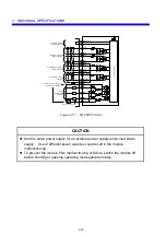
Page 97: ...se pulse input terminal Stop signal input terminal External power supply connection terminal Load connection terminal Control circuit Figure 3 57 LQC000 Circuit CAUTION z Use the same power supply for an external power supply and a load power supply Use of different power supplies could result in the module malfunctioning z To prevent the module from malfunctioning or failure switch the module off...

Page 98: ...ations T Frequency of pulses 20 kHz or lower t1 Rise Fall time 2 5μs or less t2 Duty ratio cycle with pulse frequency T 50 10 t3 Phase difference 90º 20º Figure 3 58 Pulse Waveform Specifications T t2 t2 t1 t1 ON OFF T t2 t2 t1 t1 t1 t1 T t2 t2 ON OFF ON OFF Phase A Phase B t3 t3 t3 t3 Q Single phase input Q Two phase input ...

Page 99: ...580 mA or less Dielectric voltage 1 500 VAC 1 minute between external terminals in a batch and ground External wiring Connection method 18 point terminal block connector screw M3 Compatible wire 0 3 to 1 25 mm2 Tightening torque Approx 6 to 8 N m Allowable wiring length 200 m shielded twisted pair cable Mass 230 g z The response delay does not include input filter delays z TRC denotes a remote I O...

Page 100: ...SHD SHD SHD FG LQA000 internal circuit Amplifier Figure 3 60 LQA000 Circuit RANGE0 RANGE1 0 2 047 2 000 5 5 09 RANGE2 1 0 Input voltage V A D conversion data digit Input voltage V A D conversion data digit 2 047 2 000 2 000 2 048 5 12 10 24 5 10 5 12 10 24 5 10 Figure 3 61 LQA000 A D Conversion Characteristics ...

Page 101: ...after power ON approximately 500 ms the A D conversion data is set to H000 2 MODE 2 input data format Data area EW area 215 214 213 212 211 210 29 28 27 26 25 24 23 22 21 20 S S S S S S S S S S S S S S S S S S S S Channel 0 A D conversion data Channel 1 A D conversion data Channel 2 A D conversion data Channel 3 A D conversion data A D conversion data 2 048 to 2 047 S Sign bit The content of the s...

Page 102: ...t 16 digit 14 bit 64 digit Maximum response time MODE 1 5 12 ms TRC remote I O transfer 5 12 ms RC J NET transfer MODE 2 5 12 ms 8TRC remote I O transfer 5 12 ms RC J NET transfer MODE 3 5 12 ms TRC remote I O transfer 5 12 ms RC J NET transfer MODE 4 5 12 ms 4TRC remote I O transfer 5 12 ms RC J NET transfer Input filter Attenuation factor 8 9 dB 60 Hz Time constant 4 8 ms Input impedance Power O...

Page 103: ...D conversions on inputs and sets the resulting 8 channel data in the EW area C M O D E 4 5 V Performs 12 bit A D conversions on inputs and sets the resulting 8 channel data in the EW area Provided as a mode for use on existing S10mini hardware systems 5 10 V D 10 V 6 1 to 5 V E 1 to 5 V 7 Prohibited setting F Prohibited setting z The response delay does not include input filter delays z TRC denote...

Page 104: ...A D LQA050 internal circuit Class D grounding Class D grounding Amplifier 8 channel External terminal block CAUTION Wire the cable shield to the external terminal block and use Class D grounding collectively Figure 3 64 LQA050 Circuit ...

Page 105: ... 192 10 10 24 0 0 10 10 24 Input voltage V A D conversion data digit Given 10 V inputs 8 191 2 047 8 000 2 000 2 000 8 000 2 048 8 192 5 5 09 8 191 2 047 8 000 2 000 0 0 Input voltage V A D conversion data digit Given 1 to 5 V inputs 1 Note Each number in parentheses is the result of a 14 bit conversion Figure 3 65 LQA050 A D Conversion Characteristics ...

Page 106: ...imately 500 ms the A D conversion data is set to H000 2 MODE 2 input data format Data area EW area a continuous area for setting 8 channel data in it 215 214 213 212 211 210 29 28 27 26 25 24 23 22 21 20 S S S S S S S S S S S S S S S S S S S S Channel 0 A D conversion data Channel 1 A D conversion data Channel 2 A D conversion data Channel 3 A D conversion data A D conversion data 2 048 to 2 047 S...

Page 107: ...D conversion data is set to H000 4 MODE 4 input data format Data area EW area where the two halves of the 8 channel data are set separately 215 214 213 212 211 210 29 28 27 26 25 24 23 22 21 20 S S S S S S S S S S S S S S S S S S S S Channel 0 A D conversion data Channel 1 A D conversion data Channel 2 A D conversion data Channel 3 A D conversion data A D conversion data 2 048 to 2 047 S Sign bit ...

Page 108: ...bit 16 digit 14 bit 64 digit Maximum response time MODE 1 5 12 ms TRC remote I O transfer 5 12 ms RC J NET transfer MODE 2 5 12 ms 8TRC remote I O transfer 5 12 ms RC J NET transfer MODE 3 5 12 ms TRC remote I O transfer 5 12 ms RC J NET transfer MODE 4 5 12 ms 4TRC remote I O transfer 5 12 ms RC J NET transfer Input filter Attenuation factor 8 9 dB 60 Hz Time constant 4 8 ms Input impedance Power...

Page 109: ...D conversions on inputs and sets the resulting 8 channel data in the EW area C M O D E 4 5 V Performs 12 bit A D conversions on inputs and sets the resulting 8 channel data in the EW area Provided as a mode for use on existing S10mini hardware systems 5 10 V D 10 V 6 1 to 5 V E 1 to 5 V 7 Prohibited setting F Prohibited setting z The response delay does not include input filter delays z TRC denote...

Page 110: ... Circuit 5 5 12 0 5 5 12 8 191 2 047 8 000 2 000 2 000 8 000 2 048 8 192 5 5 09 8 191 2 047 8 000 2 000 0 1 10 10 24 0 10 10 24 8 191 2 047 8 000 2 000 2 000 8 000 2 048 8 192 Input voltage V A D conversion data digit Given 5 V inputs Given 10 V inputs Note Each number in parentheses is the result of a 14 bit conversion A D conversion data digit Input voltage V Input voltage V A D conversion data ...

Page 111: ...imately 500 ms the A D conversion data is set to H000 2 MODE 2 input data format Data area EW area a continuous area for setting 8 channel data in it 215 214 213 212 211 210 29 28 27 26 25 24 23 22 21 20 S S S S S S S S S S S S S S S S S S S S Channel 0 A D conversion data Channel 1 A D conversion data Channel 2 A D conversion data Channel 3 A D conversion data A D conversion data 2 048 to 2 047 S...

Page 112: ...D conversion data is set to H000 4 MODE 4 input data format Data area EW area where the two halves of the 8 channel data are set separately 215 214 213 212 211 210 29 28 27 26 25 24 23 22 21 20 S S S S S S S S S S S S S S S S S S S S Channel 0 A D conversion data Channel 1 A D conversion data Channel 2 A D conversion data Channel 3 A D conversion data A D conversion data 2 048 to 2 047 S Sign bit ...

Page 113: ...mA or less Module REV B or later 580 mA or less Dielectric voltage 1 500 VAC 1 minute between external terminals in a batch and ground External wiring Connection method 18 point terminal strip connector screw M3 Compatible wire 0 3 to 1 25 mm2 Tightening torque Approx 6 to 8 N m Allowable wiring length 200 m shielded twisted pair cable Mass 230 g z The response delay does not include input filter ...

Page 114: ... SHD SI2 C2 SHD SI3 C3 SHD FG LQA100 internal circuit A D Channel 0 Channel 1 Channel 2 Channel 3 Amplifier Figure 3 72 LQA100 Circuit 2 047 2 000 20 20 38 4 0 Input current mA A D conversion data digit Figure 3 73 LQA100 A D Conversion Characteristics ...

Page 115: ...Immediately after power ON approximately 500 ms the A D conversion data is set to H000 2 MODE 2 input data format Data area EW area 215 214 213 212 211 210 29 28 27 26 25 24 23 22 21 20 S S S S S S S S S S S S S S S S S S S S Channel 0 A D conversion data Channel 1 A D conversion data Channel 2 A D conversion data Channel 3 A D conversion data Word 1 Word 2 Word 3 Word 4 A D conversion data 0 to 2...

Page 116: ... time MODE 1 5 12 ms TRC remote I O transfer 5 12 ms RC J NET transfer MODE 2 5 12 ms 8TRC remote I O transfer 5 12 ms RC J NET transfer MODE 3 5 12 ms TRC remote I O transfer 5 12 ms RC J NET transfer MODE 4 5 12 ms 4TRC remote I O transfer 5 12 ms RC J NET transfer Input filter Attenuation factor 8 9 dB 60 Hz Time constant 4 8 ms Input impedance Power ON 250 Ω or more Power OFF 237 Ω or more Int...

Page 117: ... 12 bit A D conversions on inputs and sets the resulting 8 channel data in the EW area C M O D E 4 4 to 20 mA Performs 12 bit A D conversions on inputs and sets the resulting 8 channel data in the EW area Provided as a mode for use on existing S10mini hardware systems 5 Prohibited setting D Prohibited setting 6 E 7 F z The response delay does not include input filter delays z TRC denotes a remote ...

Page 118: ...UTION Wire the cable shield to the external terminal block and use Class D grounding collectively Figure 3 76 LQA150 Circuit 20 20 38 8 191 2 047 8 000 2 000 0 0 Input current mA A D conversion data digit Given 4 to 20 mA inputs 4 Note Each number in parentheses is the result of a 14 bit conversion Figure 3 77 LQA150 A D Conversion Characteristics ...

Page 119: ...imately 500 ms the A D conversion data is set to H000 2 MODE 2 input data format Data area EW area a continuous area for setting 8 channel data in it 215 214 213 212 211 210 29 28 27 26 25 24 23 22 21 20 S S S S S S S S S S S S S S S S S S S S Channel 0 A D conversion data Channel 1 A D conversion data Channel 2 A D conversion data Channel 3 A D conversion data A D conversion data 0 to 2 047 S Sig...

Page 120: ...D conversion data is set to H000 4 MODE 4 input data format Data area EW area where the two halves of the 8 channel data are set separately 215 214 213 212 211 210 29 28 27 26 25 24 23 22 21 20 S S S S S S S S S S S S S S S S S S S S Channel 0 A D conversion data Channel 1 A D conversion data Channel 2 A D conversion data Channel 3 A D conversion data A D conversion data 0 to 2 047 S Sign bit The ...

Page 121: ...se time MODE 1 5 12 ms TRC remote I O transfer 5 12 ms RC J NET transfer MODE 2 5 12 ms 8TRC remote I O transfer 5 12 ms RC J NET transfer MODE 3 5 12 ms TRC remote I O transfer 5 12 ms RC J NET transfer MODE 4 5 12 ms 4TRC remote I O transfer 5 12 ms RC J NET transfer Input filter Attenuation factor 8 9 dB 60 Hz Time constant 4 8 ms Input impedance Power ON 250 Ω or more Power OFF 237 Ω or more I...

Page 122: ... 12 bit A D conversions on inputs and sets the resulting 8 channel data in the EW area C M O D E 4 4 to 20 mA Performs 12 bit A D conversions on inputs and sets the resulting 8 channel data in the EW area Provided as a mode for use on existing S10mini hardware systems 5 Prohibited setting D Prohibited setting 6 E 7 F z The response delay does not include input filter delays z TRC denotes a remote ...

Page 123: ...erminal block A A CAUTION Wire the cable shield to the external terminal block and use Class D grounding collectively Figure 3 80 LQA155 Circuit 20 20 38 8 191 2 047 8 000 2 000 0 0 4 Note Each number in parentheses is the result of a 14 bit conversion Input current mA A D conversion data digit Figure 3 81 LQA155 A D Conversion Characteristics ...

Page 124: ...imately 500 ms the A D conversion data is set to H000 2 MODE 2 input data format Data area EW area a continuous area for setting 8 channel data in it 215 214 213 212 211 210 29 28 27 26 25 24 23 22 21 20 S S S S S S S S S S S S S S S S S S S S Channel 0 A D conversion data Channel 1 A D conversion data Channel 2 A D conversion data Channel 3 A D conversion data A D conversion data 0 to 2 047 S Sig...

Page 125: ...D conversion data is set to H000 4 MODE 4 input data format Data area EW area where the two halves of the 8 channel data are set separately 215 214 213 212 211 210 29 28 27 26 25 24 23 22 21 20 S S S S S S S S S S S S S S S S S S S S Channel 0 A D conversion data Channel 1 A D conversion data Channel 2 A D conversion data Channel 3 A D conversion data A D conversion data 0 to 2 047 S Sign bit The ...

Page 126: ...500 VAC 1 minute between external terminals in a batch and ground External wiring Connection method 18 point terminal block connector screw M3 Compatible wire 0 3 to 1 25 mm2 Tightening torque Approx 6 to 8 N m Allowable wiring length 200 m shielded twisted pair cable Mass 240 g z The response delay does not include input filter delays z TRC denotes a remote I O transfer time z RC denotes a refres...

Page 127: ...ircuit 2 047 1 684 1 712 1 791 1 823 2 048 100 100 0 A D conversion data digit Temperature RANGE0 100 to 100 input 2 047 1 827 1 857 1 245 1 266 2 048 350 200 0 A D conversion data digit Temperature RANGE2 300 to 500 input RANGE1 200 to 350 input 2 047 1 876 1 907 934 950 2 048 500 200 A D conversion data digit Temperature 0 The A D conversion data shows the values when using Pt100 The data in par...

Page 128: ...Immediately after power ON approximately 500 ms the A D conversion data is set to H000 2 Mode 2 input data format Data area EW area 215 214 213 212 211 210 29 28 27 26 25 24 23 22 21 20 S S S S S Channel 0 A D conversion data S S S S S Channel 1 A D conversion data S S S S S Channel 2 A D conversion data S S S S S Channel 3 A D conversion data Word 1 Word 2 Word 3 Word 4 A D conversion data 2 048 ...

Page 129: ...VAC 1 minute between external terminals in a batch and ground External wiring Connection method 18 point terminal block connector screw M3 Compatible wire 0 3 to 1 25 mm2 Tightening torque Approx 6 to 8 N m Allowable wiring length 200 m shielded twisted pair cable Mass 240 g z The response delay does not include input filter delays z TRC denotes a remote I O transfer time z RC denotes a refresh cy...

Page 130: ...201 Circuit 50 2 047 1 987 2 021 0 150 703 716 2 048 Temperature A D conversion data digit RANGE0 50 to 150 input RANGE1 200 to 100 input 200 2 047 840 855 0 100 1 864 1 896 2 048 A D conversion data digit Temperature 100 2 047 1 903 1 934 0 300 715 728 2 048 Temperature A D conversion data digit RANGE2 100 to 300 input The A D conversion data shows the values when using Pt100 The data in parenthe...

Page 131: ...Immediately after power ON approximately 500 ms the A D conversion data is set to H000 2 Mode 2 input data format Data area EW area 215 214 213 212 211 210 29 28 27 26 25 24 23 22 21 20 S S S S S Channel 0 A D conversion data S S S S S Channel 1 A D conversion data S S S S S Channel 2 A D conversion data S S S S S Channel 3 A D conversion data Word 1 Word 2 Word 3 Word 4 A D conversion data 2 048 ...

Page 132: ... 1 500 VAC 1 minute between external terminals in a batch and ground External wiring Connection method 18 point terminal block connector screw M3 Compatible wire 0 3 to 1 25 mm2 Tightening torque Approx 6 to 8 N m Allowable wiring length 200 m shielded twisted pair cable Mass 240 g z TRC denotes a remote I O transfer time z RC denotes a refresh cycle time set from J NET z While a data transfer on ...

Page 133: ...it SV1 C1 SHD SV2 C2 SHD SV3 C3 SHD FG L L L L Figure 3 92 LQA500 Circuit 4 095 4 000 5 5 09 RANGE2 1 0 Output voltage V D A conversion data digit 2 047 2 000 2 048 10 5 10 24 5 12 5 10 5 12 10 24 RANGE1 RANGE0 Output voltage V D A conversion data digit 0 2 000 Figure 3 93 LQA500 D A Conversion Characteristics ...

Page 134: ...No effect No effect No effect No effect Word 1 Word 2 Word 3 Word 4 D A conversion data 0 to 4 095 2 Mode 2 output data format Data area EW area RANGE switch set to 0 or 1 215 214 213 212 211 210 29 28 27 26 25 24 23 22 21 20 No effect No effect No effect No effect S S S S Channel 0 D A conversion data Channel 1 D A conversion data Channel 2 D A conversion data Channel 3 D A conversion data Word 1...

Page 135: ...500 VAC 1 minute between external terminals in a batch and ground External wiring Connection method 18 point terminal block connector screw M3 Compatible wire 0 3 to 1 25 mm2 Tightening torque Approx 6 to 8 N m Allowable wiring length 200 m or less shielded twisted pair cable Mass 240 g z TRC denotes a remote I O transfer time z RC denotes a refresh cycle time set from J NET z While a data transfe...

Page 136: ...25 24 23 22 21 20 Channel 0 D A conversion data Channel 1 D A conversion data Channel 2 D A conversion data Channel 3 D A conversion data No effect No effect No effect No effect Word 1 Word 2 Word 3 Word 4 D A conversion data 0 to 4 095 2 Mode 2 output data format Data area EW area 215 214 213 212 211 210 29 28 27 26 25 24 23 22 21 20 No effect No effect No effect No effect Channel 0 D A conversio...

Page 137: ...ernal terminals in a batch and ground External wiring Connection method 18 point terminal block connector screw M3 Compatible wire 0 3 to 1 25 mm2 Tightening torque Approx 6 to 8 N m Allowable wiring length 200 m or less shielded twisted pair cable Mass 240 g z The response delay does not include input filter delays z TRC denotes a remote I O transfer time z RC denotes a refresh cycle time set fro...

Page 138: ...6 25 24 23 22 21 20 Channel 0 D A conversion data Channel 1 D A conversion data Channel 2 D A conversion data Channel 3 D A conversion data No effect No effect No effect No effect Word 1 Word 2 Word 3 Word 4 D A conversion data 0 to 4 095 2 Mode 2 output data format Data area EW area 215 214 213 212 211 210 29 28 27 26 25 24 23 22 21 20 No effect No effect No effect No effect Channel 0 D A convers...

Page 139: ...1 MΩ or more Internal current dissipation LQA301 500 mA or less LQA310 100 mA or less Dielectric voltage 500 VDC 1 minute between external terminals in a batch and ground External wiring Connection method 18 point terminal block connector screw M3 Compatible wire 0 3 to 1 25 mm2 Tightening torque Approx 6 to 8 N m Allowable wiring length 200 m or less shielded twisted pair cable Mass LQA301 170 g ...

Page 140: ...12 211 210 20 S S S S S Channel 0 A D conversion data S S S S S Channel 1 A D conversion data S S S S S Channel 2 A D conversion data S S S S S Channel 3 A D conversion data Word 1 Word 2 Word 3 Word 4 A D conversion data 2 048 to 2 047 S Sign bit The content of the sign bit is reflected here Figure 3 105 LQA301 and LQA310 A D Figure 3 106 Input Data Format Conversion Characteristics Data area EW ...

Page 141: ... MΩ or more Internal current dissipation LQA800 500 mA or less LQA810 100 mA or less Dielectric voltage 1 500 VAC 1 minute between external terminals in a batch and ground External wiring Connection method 18 point terminal block connector screw M3 Compatible wire 0 3 to 1 25 mm2 Tightening torque Approx 6 to 8 N m Allowable wiring length 200 m or less shielded twisted pair cable Mass LQA800 170 g...

Page 142: ...11 210 20 S S S S S Channel 0 A D conversion data S S S S S Channel 1 A D conversion data S S S S S Channel 2 A D conversion data S S S S S Channel 3 A D conversion data Word 1 Word 2 Word 3 Word 4 A D conversion data 2 048 to 2 047 S Sign bit The content of the sign bit is reflected here Figure 3 109 LQA800 and LQA810 A D Figure 3 110 Input Data Format Conversion Characteristics for Remote I O Co...

Page 143: ...This Page Intentionally Left Blank ...

Page 144: ...4 HANDLING ...

Page 145: ...o the CPU module leaving one slot space apart from the I O modules Further keep the wirings for option and I O modules separated z Install I O modules rated at 24 VDC or less and those rated at 100 VAC or 100 VDC or more apart from one another z Install analog input output and analog counter modules one slot space apart from I O modules rated at 100 VAC or 100 VDC or more z Separate wirings for I ...

Page 146: ...e Soldered connection Fujitsu Devices Inc FCN 361J040 AU connector FCN 360C040 B connector cover Solderless connection Fujitsu Devices Inc FCN 363J040 housing FCN 363J AU contact FCN 360C040 B connector cover Pressure connection Fujitsu Devices Inc FCN 367J040 AU F LQX310 LQX360 LQY310 LQY360 Connection method Compatible connector type Pressure connection DDK Ltd FRC3 O34 10S 4 2 2 Analog input ou...

Page 147: ...Solderless terminals Shielded twisted pair cable Harness band Bundle signal and common lines in the same harness 5 VDC 10 V 1 to 5 V Wiring LQX and LQY Wiring LQA and LQC000 Figure 4 2 Wiring I O Modules Round Tongue style 7 or less 7 or less Example R1 25 3 Example 1 25 YS3A 6 Solderless terminals Heat shrinkable tube Cable Shield wire Solderless terminals Attaching solderless terminals to a cabl...

Page 148: ... must be wired as follows y If the pulse counter module is used with one phase pulse input short the two input terminals of each of the two pairs of two phase pulse input terminals that is short A1S and A1C together then short B1S and B1C together and then ground them all together y If it is used with two phase pulse input short the one phase pulse input terminals A2S and A2C together and then gro...

Page 149: ...mpedance of the input module or Input Common AC input module Leakage current Resistance Figure 4 4 Connecting a Resistance to an AC Input Module If leakage current makes for false DC inputs such as a switch with an LED indicator connect a resistance as shown below to hold the voltage present between the input terminal and the common to the OFF voltage or below Input Common DC input module Leakage ...

Page 150: ...Any digital input module with built in signal latches contains signal memory elements flip flops or simply FFs which are used to store external input signals Once an external input signal is turned on a given contact e g X000 will remain on indefinitely so the circuit containing the contact must perform latch reset output depending on the contact used as the condition X000 In this example when the...

Page 151: ... the module s built in FF is latched The input indicator LED in the module s front panel comes on when the FF is latched and goes out when it is reset The on data of the FF is transferred to the contact data item X000 in the CPU by a remote I O transfer The ladder program used turns on the latch reset output Y000 The output Y000 is transferred to the module by a next remote I O transfer and the FF...

Page 152: ...her voltage and a higher current level than the rated their useful service life will be shorter than expected The other factors that will make the service life shorter than expected are the following ambient operating environment type of the load connected in rush current and serge So pay special attention to those factors when installing any of the above mentioned hardware modules As a rule each ...

Page 153: ...ut Actions 2 The c contact typically touches either contact when the other contact is released but contact to contact arcing could cause the a and b contacts to be shorted to each other Never make a connection like that shown below because such a connection is hazardous a b c Module side RY L Figure 4 8 Example of a Prohibited Connection of the LQY160 and LQY170 3 Voltage supply to the RY output e...

Page 154: ...e positive side of a DC load or on both sides of an AC load LQY200 5 A Install one fuse per common Install one on the positive side of a 24 VDC power supply LQY300 LQY310 3 A Install one fuse per common Install one on the positive side of a 24 VDC power supply LQY350 LQY360 3 A Install one fuse per common Install one on the positive side of a 24 VDC power supply LQZ300 3 A Install one fuse per com...

Page 155: ...nal inputs from A1 and B1 cause the pulse counter to increment or decrement at the timing shown below A1 B1 Up Down Up Q The pulse counter module functions as a ring counter yIn operation mode 1 When the counter increments from 16 383 once the count is set to 0 When the counter decrements from 0 once the count is set to 16 383 yIn operation mode 2 When the counter increments from 8 191 once the co...

Page 156: ... output The result of comparison of compare data value R and count value C is output R C Output when R C R C Output when R C R C Output when R C R C held until a latch reset is implemented by setting a control code f LED indications y Pulse input indication LED Flashes in sync with a count of single or two phase pulses y Compare result indication LED Lights in sync with comparator output Q The com...

Page 157: ...areas EW400 to EWFB0 It is necessary to register a module mounting address XW YW in the data area before using the LQC000 For more information on registering module mounting addresses refer to Section 3 2 Address Registration in 4 Channel Analog Pulse Counter For Windows Manual number SAE 3 142 a Data area format The data area format is shown below EW 0 EW 0 10 EW 0 20 EW 0 30 Write data Control c...

Page 158: ...eset value in the counter and starts measurement 2 Compare value set Sets a compare value in the comparator register and starts measurement 1 Latch reset Resets the match output signal latched and starts measurement None of above No effect Q Operation mode 2 Control code Explanation Action when set 8 Count stop Stops pulse measurement 4 Preset start Sets a preset value in the counter and starts me...

Page 159: ... 1 Status code Explanation Status 8 Count stop Counting stopped 4 R C Compare data value larger than the count value 2 R C Compare data value equal to the count value 1 R C Compare data value less than the count value If R C has been latched status code 2 R C is set even though the comparator result is R C or R C Q Operation mode 2 Status code Explanation Status 8 Count stop Sets the last transfer...

Page 160: ... coil E41D g Sample program y Operation Start a motor with an externally supplied start signal and then measure the pulses generated from an encoder rotating with the movement of the traveling table to let the motor move to a predefined position and stop y Requirement Let the program run in the flow shown Figurer 4 10 y Configuration See below Motor Traveling table Encoder Y030 Y031 X020 X010 X011...

Page 161: ...alue Operation mode 1 Count stop z Status code Operation mode 2 Count stop Preset start Compare value set Latch reset Compare value set Compare value set Start of motor forwarding Start of motor reversing Preset start Compare value set 1 Count value Time 2 1 If R C is set the status code is held at R C until the latch is reset 2 In operation mode 2 the flow designated by continuous dotted lines ta...

Page 162: ...g Second compare value EW400 H2 EW400 H1 EW410 H1 R011 Start of motor reversing H8 EW410 H1 R012 Second preset value EW400 H4 EW410 Third compare value EW400 H2 EW410 H1 EW410 H1 R013 H8 EW410 H1 EW410 H1 R014 H1 R010 2 F DST F DST F DST F DST F DST F DST F DST F DST F DST F DST F DST F DST F DST F DST F DST F DST F DST F DST F DST F DST F DST F DST 1 1 1 1 1 1 1 1 1 1 1 1 1 1 1 1 1 1 1 Allow for ...

Page 163: ...ion of a Remote I O Transfer Operation mode Operation mode 1 Operation mode 2 1 Operation mode 2 2 Remote I O status Transfer suspended Transfer resumed Transfer suspended Transfer resumed Transfer suspended Transfer resumed Module status Normal operation 3 Normal operation Normal operation 3 Normal operation Count stop Normal operation LQC000 internal register Preset value Clear Compare value Hol...

Page 164: ...l operation Normal operation 3 Normal operation Count stop Normal operation LQC000 internal register Preset value Clear Compare value Hold Count value Clear Compare output R C Hold R C OFF R C Hold LED indication R C Hold R C OFF R C Normal operation 3 Normal operation Normal operation 3 Normal operation Hold Normal operation 1 The output hold terminals of the station module are shorted 2 The outp...

Page 165: ...nse type No matter how many channels are used it will occupy 16 I O points Response time is LQA000 LQA100 5 ms 4TRC LQA200 LQA201 10 ms 4TRC LQA500 LQA600 LQA610 4 ms 4TRC TRC Remote I O transfer time 4 5 1 If mode 1 is set Analog data is moved in and out of the XW and YW area in this mode The number of channels available depends on the I O count setting of the CPU and the remote I O station Chann...

Page 166: ...50 YW060 YW070 Channel 0 Channel 1 Channel 2 Channel 3 Channel 0 Channel 1 Channel 2 Channel 3 L Q A 5 0 0 L Q A 5 0 0 Power supply Station Power supply Station 4 5 2 If mode 2 is set Analog data is moved in and out of the EW area in this mode To perform input and output to and from the EW area the input and output addresses and the module type must be registered by using a programming tool To fin...

Page 167: ...o D30 08 EW780 to 7B0 20 EWD80 to DB0 09 EW800 to 830 21 EWE00 to E30 10 EW880 to 8B0 22 EWE80 to EB0 11 EW900 to 930 23 EWF00 to F30 12 EW980 to 9B0 24 EWF80 to FB0 The flow of data for allocating the XW YW 000 to registration number 01 is shown below EW400 EW410 EW420 EW430 XW YW 000 CPU module Con version Channel 0 analog data Channel 1 analog data Channel 2 analog data Channel 3 analog data Re...

Page 168: ...h a maximum response time of 5 12 ms plus one TRC This mode will occupy 128 I O points 14 bit A D conversion data if all the available eight channels are used y MODE4 A low speed response mode with a maximum response time of 5 12 ms plus four TRCs This mode will occupy 32 I O points regardless of how many channels are used among the available eight Note Each TRC is a remote I O transfer duration 4...

Page 169: ... 0 Channel 1 I O units L Q A 0 5 0 Power supply Station 4 6 2 MODE2 setting This mode of operation writes analog data to the EW area and reads it from that area To input analog data to the EW area you must register input addresses and module types with your user system by using an appropriate programming tool For details refer to the following manuals Manual name Manual number S10 Tools For Window...

Page 170: ... models and revisions associated with the CPU LPU and the versions of programming tools in order to use MODE2 Module types and revisions Module type Indicator indication Tool window indication Module revision LQP000 CPMS M15 or later G or later LQP010 CPMS M15 or later G or later LQP011 CPMS M15 or later H or later LQP120 CPMS M14 or later E or later LQP510 Ver 2 0 Rev 1 0 or later F or later LQP7...

Page 171: ...450 EW460 EW470 Analog data of channel 0 Conversion Analog data pieces each including channel info XW000 8 channel analog input module Remote I O communication line CPU Analog data of channel 1 Analog data of channel 2 Analog data of channel 3 Analog data of channel 4 Analog data of channel 5 Analog data of channel 6 Analog data of channel 7 Analog data of channel 0 Analog data of channel 1 Analog...

Page 172: ...as used for MODE2 For information on the required manuals and the relationships between all possible registration numbers and allocated data areas see Section 4 6 2 MODE2 setting y Module mounting Any 8 channel analog input module used in this mode is treated as if two conventional 4 channel analog input modules were mounted in a single slot The figures below shows examples of mounting an 8 channe...

Page 173: ... 3 each including channel info XW000 CPU XW010 Analog data of channel 1 Analog data of channel 2 Analog data of channel 3 Analog data of channel 4 Analog data of channel 5 Analog data of channel 6 Analog data of channel 7 Conversion 1 Conversion 2 Analog data pieces 4 thru 7 each including channel info 8 channel analog input module Remote I O communication line Analog data of channel 0 Analog data...

Page 174: ...stall them in the slots to the right of the scanner modules Correct Incorrect PS ST AD Scanner Scanner Scanner Standard I O Standard I O Standard I O Standard I O PS ST AD Standard I O Scanner Scanner Standard I O Scanner Standard I O Standard I O 4 7 2 Wiring modules Follow the instructions in Section 4 2 Wiring I O Modules to wire modules 4 7 3 Usage Scan type analog input modules enter analog d...

Page 175: ... LQA100 PAF300 AI 04 z Mount the scanner module in slots 0 and 1 XW020 XW030 Transfer 4 channels of data to the starting word of each slot EW400 EW410 EW420 EW430 Channel 0 Channel 1 Channel 2 Channel 3 Channels 0 to 3 Undefined data XW040 XW050 EW480 EW490 EW4A0 EW4B0 Channel 0 Channel 1 Channel 2 Channel 3 Channels 0 to 3 Undefined data XW000 and XW010 are invalid areas Expand the data transferr...

Page 176: ...0 LQA150 LQA155 LQA200 LQA201 LQA500 LQA600 LQA610 LQA301 LQA310 LQA800 LQA810 Unit mm 2 LQX200 LQX201 LQY100 LQY140 LQY200 Unit mm B1 B2 B3 B4 B5 B6 B7 B8 B9 A1 A2 A3 A4 A5 A6 A7 A8 A9 34 0 87 5 6 5 13 5 19 0 21 5 100 2 130 0 34 0 100 2 130 0 B1 B2 B3 B4 B5 B6 B7 B8 B9 A1 A2 A3 A4 A5 A6 A7 A8 A9 87 5 6 5 13 5 19 0 Where the ornamental cover is installed Where the ornamental cover is removed ...

Page 177: ...al dimensions 3 LQX150 LQX151 LQY170 Unit mm 4 LQX300 LQY300 Unit mm 5 LQX350 LQY350 Unit mm B1 B2 B3 B4 B5 B6 B7 B8 B9 A1 A2 A3 A4 A5 A6 A7 A8 A9 34 0 87 5 6 5 13 5 19 0 21 5 140 0 130 0 34 0 74 0 4 0 7 0 12 0 2 3 100 2 130 0 34 0 74 0 4 0 7 0 24 0 2 3 100 2 130 0 ...

Page 178: ...imensions 3 3 No Type External dimensions 6 LQX310 LQY310 Unit mm 7 LQX360 LQY360 Unit mm 8 LQZ300 Unit mm 34 0 78 0 7 0 8 0 12 0 2 3 100 2 130 0 19 0 34 0 78 0 7 0 8 0 24 0 2 3 100 2 130 0 19 0 3 0 34 0 74 0 4 0 7 0 24 0 2 3 100 2 130 0 ...

Page 179: ...This Page Intentionally Left Blank ...

Page 180: ...5 HANDLING I O DATA ON J NET ...

Page 181: ...DR DW DI J STATION STANDARD Setting not required J STATION EXTENDED DI MODE2 J STATION EXTENDED S10 DI 4ch 8 channel analog input module MODE1 AUTO Setting not required I O DI I O DR DW DI J STATION STANDARD Setting not required J STATION EXTENDED DI MODE2 Not usable MODE3 AUTO Setting not required I O DI I O DR DW DI J STATION STANDARD Setting not required J STATION EXTENDED DI MODE4 Not usable 4...

Page 182: ... 23 22 21 20 0 0 0 0 S Channel 0 A D conversion data 0 0 0 0 S Channel 1 A D conversion data 0 0 0 0 S Channel 2 A D conversion data 0 0 0 0 S Channel 3 A D conversion data Word 1 Word 2 Word 3 Word 4 A D conversion data 2 048 to 2 047 S Sign bit y When the station type is AUTO J STATION STANDARD or the I O type is AI 215 214 213 212 211 210 29 28 27 26 25 24 23 22 21 20 S Channel 0 A D conversion...

Page 183: ... 0 S Channel 5 A D conversion data 0 0 0 0 S Channel 6 A D conversion data 0 0 0 0 Word 5 Word 6 Word 7 Word 8 A D conversion data 2 048 to 2 047 S Sign bit y Data format used in MODE3 not dependent on I O types and station types 215 214 213 212 211 210 29 28 27 26 25 24 23 22 21 20 S Channel 0 A D conversion data 0 0 S Channel 1 A D conversion data 0 0 S Channel 2 A D conversion data 0 0 S Channe...

Page 184: ... D A conversion data Word 1 Word 2 Word 3 Word 4 D A conversion data 0 to 4 095 S Sign bit y When the station type is AUTO J STATION STANDARD or when the I O type is AI and the RANGE switch is set in 0 or 1 position 215 214 213 212 211 210 29 28 27 26 25 24 23 22 21 20 S Channel 0 D A conversion data Unused S Channel 3 D A conversion data Unused S Channel 2 D A conversion data Unused S Channel 1 D...

Page 185: ...rsion data Unused Channel 3 D A conversion data Word 1 Word 2 Word 3 Word 4 D A conversion data 0 to 4 095 S Sign bit y When the station type is AUTO J STATION STANDARD or the I O type is AO 215 214 213 212 211 210 29 28 27 26 25 24 23 22 21 20 Channel 0 D A conversion data Unused Channel 3 D A conversion data Unused Channel 2 D A conversion data Unused Channel 1 D A conversion data Unused Word 1 ...

Page 186: ...6 HANDLING I O DATA ON D Station ...

Page 187: ...Pulse Counter Module Data Format Data transfer mode Data format Normal transfer mode MSB 215 22 21 20 Read write count data Control code Status code when read Control code Mode 1 Mode 2 0 0 Counter stop Counter stop 0 1 Preset start Preset start 1 0 Compare value set Compare value set 1 1 Latch reset Latch reset Status code Mode 1 Mode 2 0 0 Counter stop Counter stop 0 1 R C Preset start 1 0 R C C...

Page 188: ...0 0 0 0 S Channel 5 A D conversion data 0 0 0 0 S Channel 6 A D conversion data 0 0 0 0 Word 5 Word 6 Word 7 Word 8 A D conversion data 2 048 to 2 047 S Sign bit 8 channel analog mode 3 215 214 213 212 211 210 29 28 27 26 25 24 23 22 21 20 S Channel 0 A D conversion data 0 0 S Channel 1 A D conversion data 0 0 S Channel 2 A D conversion data 0 0 S Channel 7 A D conversion data 0 0 S Channel 3 A D ...

Page 189: ...e LQA600 LQA610 the sign bit becomes the most significant bit of the D A conversion data The data ranges from 0 to 4 095 Output data is set to 0000 immediately after power ON for approximately 0 5 second Analog 4 bit shift mode MSB 215 212 211 20 Word 1 No effect S Channel 0 D A conversion data Word 2 No effect S Channel 1 D A conversion data Word 3 No effect S Channel 2 D A conversion data Word 4...

Page 190: ...6 HANDLING I O DATA ON D Station 6 5 6 5 Scan type Analog Input Modules The scan type analog input modules LQA3 LQA8 cannot work in conjunction with a D Station ...

Page 191: ...This Page Intentionally Left Blank ...

Page 192: ...7 MAINTENANCE ...

Page 193: ...usual status Mounting screw and terminal block screw tightness Check the screws such as those used to mount the module and the terminal block screws for tightness If found loose tighten them fully Loose screws could cause the system to malfunction or get burnt under heat Cable and wire covering status Check the cable and wire coverings for defects and abnormal heat Coverings out of position or hea...

Page 194: ...le at the SERVICE CHECK terminals shown below For how to test the operating supply voltages of each module and external supply voltages refer to the relevant manuals PS LQV000 POWER ON OFF H N LG FG AC100 120V INPUT DC5V GND SERVICE CHECK POWER SERVICE CHECK terminals Figure 7 1 LQV000 Appearance CAUTION z If the input voltage of the power supply module is within its specified range but it is clos...

Page 195: ... ON OFF H N LG FG 100 120 VAC 5 VDC GND SERVICE CHECK POWER D INPUT LQX100 100 120VAC 0 1 2 3 4 5 6 7 8 9 A B C D E F D INPUT LQX100 100 120VAC 0 1 2 3 4 5 6 7 8 9 A B C D E F CPU RUN Figure 7 2 Troubleshooting Failures in the CPU Unit I O unit Two slot mount base Operation indication LED Indicating LEDs Power supply module Station module I O modules PS LQV000 POWER ON OFF H N LG FG 100 120 VAC 5 ...

Page 196: ...ning a ladder program and has paused a remote I O transfer CPU STOP Has paused a ladder program and executing a remote I O transfer y If the indicator shows the condition described below troubleshoot the failure by taking the corrective action suggested Table 7 3 CPU Indicator Indication Suggesting an Error Indication Corrective action IO T Transfer of remote I O data to and from the I O address 0...

Page 197: ...supply module I O modules All I O modules are inoperable Replace the power supply module The I O module mounted on an I O unit is inoperable Replace the CPU module Only a particular I O module is inoperable Replace the I O module CAUTION The customer is cautioned not to replace any internal components of the S10mini CPU except for the battery We do not assume responsibility for any consequential d...

Reviews: