3 INDIVIDUAL SPECIFICATIONS
3-60
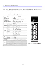
y
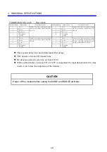
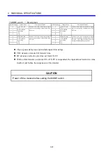
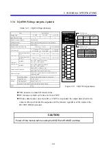
MODE switch
-
Description
Switch setting
Input voltage
Description of mode
Switch setting
Input voltage
Description of mode
0
M
O
D
E
1
4 to 20 mA
Performs 12-bit A/D conversions on inputs
and sets the resulting 8-channel data in the
XW area.
8
M
O
D
E
3
4 to 20 mA
Performs 14-bit A/D conversions on inputs
and sets the resulting 8-channel data in the
XW area.
1 Prohibited
setting
9
Prohibited
setting
2
A
3
B
4
M
O
D
E
2
4 to 20 mA
Performs 12-bit A/D conversions on inputs
and sets the resulting 8-channel data in the
EW area.
C
M
O
D
E
4
4 to 20 mA
Performs 12-bit A/D conversions on inputs
and sets the resulting 8-channel data in the
EW area. (Provided as a mode for use on
existing S10mini hardware systems.)
5 Prohibited
setting
D
Prohibited
setting
6
E
7
F
z
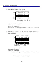
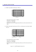
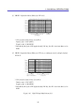
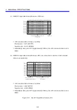
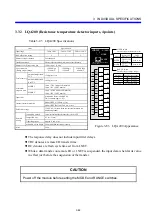
The response delay does not include input filter delays.
z
TRC denotes a remote I/O transfer time.
z
RC denotes a refresh cycle time set from J.NET.
z
While a data transfer on remote I/O or J.NET is suspended, the input data is held at its value
in effect just before the suspension of the transfer.
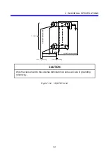
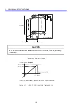
CAUTION
Power off the module before setting the MODE switch.
Summary of Contents for S10mini LQS070
Page 1: ......
Page 2: ......
Page 19: ...This Page Intentionally Left Blank ...
Page 30: ...1 BEFORE USE ...
Page 37: ...This Page Intentionally Left Blank ...
Page 38: ...2 KINDS AND SPECIFICATIONS OF I O MODULES ...
Page 57: ...This Page Intentionally Left Blank ...
Page 58: ...3 INDIVIDUAL SPECIFICATIONS ...
Page 143: ...This Page Intentionally Left Blank ...
Page 144: ...4 HANDLING ...
Page 179: ...This Page Intentionally Left Blank ...
Page 180: ...5 HANDLING I O DATA ON J NET ...
Page 186: ...6 HANDLING I O DATA ON D Station ...
Page 191: ...This Page Intentionally Left Blank ...
Page 192: ...7 MAINTENANCE ...

