4 HANDLING
4-7
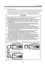
(a) Applied to AC and DC
(b) Applied to AC and DC
Load
L
r
c
r = Load impedance
c = 0.1
μ
F
Output module
Load
L
Varistor
Output module
(c) DC
only
Load
L
Output module
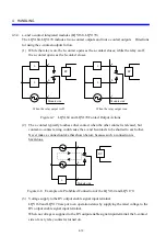
Figure 4-6 Surge Absorbers Circuit
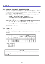
4.3.2 Digital input modules with built-in signal latches
(LQX110, LQX151, LQX210, LQX211, LQX250)
(1) How to use the module
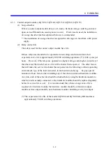
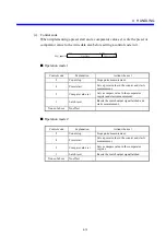
Any digital input module with built-in signal latches contains signal memory elements
(flip-flops or, simply, FFs) which are used to store external input signals. Once an
external input signal is turned on, a given contact (e.g., X000) will remain on indefinitely,
so the circuit containing the contact must perform latch reset output, depending on the
contact used as the condition.
X000
In this example, when the coil
having the same number as the
external input contact is turned on,
the latch X000 would be reset.
Latch reset output
Y000
Summary of Contents for S10mini LQS070
Page 1: ......
Page 2: ......
Page 19: ...This Page Intentionally Left Blank ...
Page 30: ...1 BEFORE USE ...
Page 37: ...This Page Intentionally Left Blank ...
Page 38: ...2 KINDS AND SPECIFICATIONS OF I O MODULES ...
Page 57: ...This Page Intentionally Left Blank ...
Page 58: ...3 INDIVIDUAL SPECIFICATIONS ...
Page 143: ...This Page Intentionally Left Blank ...
Page 144: ...4 HANDLING ...
Page 179: ...This Page Intentionally Left Blank ...
Page 180: ...5 HANDLING I O DATA ON J NET ...
Page 186: ...6 HANDLING I O DATA ON D Station ...
Page 191: ...This Page Intentionally Left Blank ...
Page 192: ...7 MAINTENANCE ...

