4 HANDLING
4-10
4.3.4 a- and c-contact integrated modules (LQY160, LQY170)
The LQY160, LQY170 includes two a-contact outputs and four c-contact outputs. Directions
for using the c-contact outputs follow.
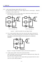
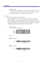
(1) While the relay is on, the b-contact opens as the a-contact closes; while the relay is off,
the a-contact opens as the b-contact closes.
L
a
L
b
c
Module side
RY
When the relay output is off
L
a
L
b
c
Module side
RY
When the relay output is on
Figure 4-7 LQY160 and LQY170 Contact Output Actions
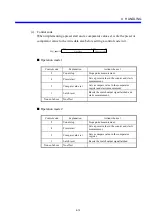
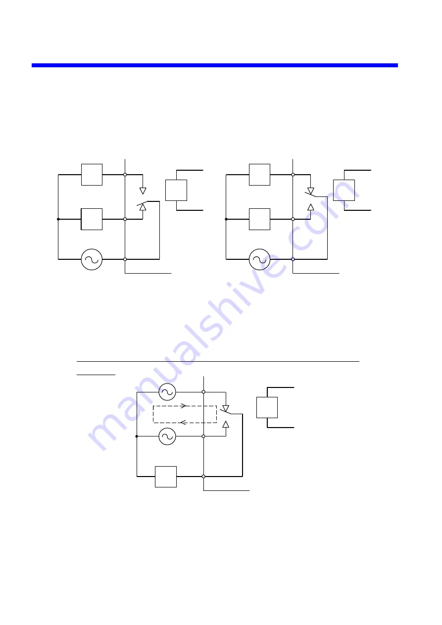
(2) The c-contact typically touches either contact when the other contact is released, but
contact-to-contact arcing could cause the a- and b-contacts to be shorted to each other.
Never make a connection like that shown below, because such a connection is
hazardous.
a
b
c
Module side
RY
L
Figure 4-8 Example of a Prohibited Connection of the LQY160 and LQY170
(3) Voltage supply to the RY output enable signal input terminal
LQY160 and LQY170 are put to an operation status by supplying the rated voltage to the
RY output enable signal input terminal.
When no voltage is supplied to the RY output enable signal input terminal, the b-contact
side of every relay contact is turned on.
Summary of Contents for S10mini LQS070
Page 1: ......
Page 2: ......
Page 19: ...This Page Intentionally Left Blank ...
Page 30: ...1 BEFORE USE ...
Page 37: ...This Page Intentionally Left Blank ...
Page 38: ...2 KINDS AND SPECIFICATIONS OF I O MODULES ...
Page 57: ...This Page Intentionally Left Blank ...
Page 58: ...3 INDIVIDUAL SPECIFICATIONS ...
Page 143: ...This Page Intentionally Left Blank ...
Page 144: ...4 HANDLING ...
Page 179: ...This Page Intentionally Left Blank ...
Page 180: ...5 HANDLING I O DATA ON J NET ...
Page 186: ...6 HANDLING I O DATA ON D Station ...
Page 191: ...This Page Intentionally Left Blank ...
Page 192: ...7 MAINTENANCE ...

