4 HANDLING
4-17
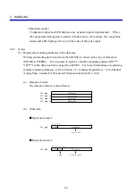
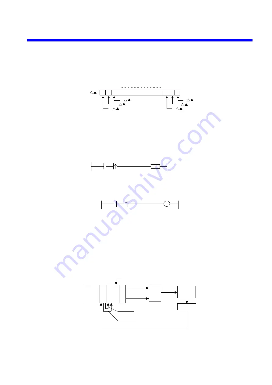
(f) Data area bit structure
Because the EW data area is structured as shown below, an operation code and a
status code in it can be used as a ladder contact and a coil, respectively.
EW
0
2
0
2
15
2
14
2
13
2
1
2
2
E
0
E
1
E
2
E
D
E
E
E
F
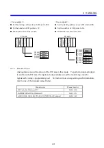
When a preset restart is implemented, for example, it can be set either as an
arithmetic function or as a coil as shown below.
z
Using an arithmetic function
DST
H4 = EW410
F
z
Using a coil
E41D
(g) Sample
program
y
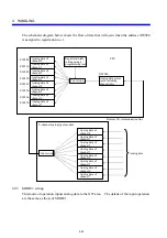
Operation: Start a motor with an externally supplied start signal and then measure
the pulses generated from an encoder rotating with the movement of the
traveling table to let the motor move to a predefined position and stop.
y
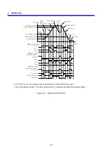
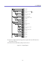
Requirement: Let the program run in the flow shown Figurer 4-10.
y
Configuration: See below.
Motor
Traveling
table
Encoder
Y030
Y031
X020
X010
X011
Motor forwarding
Motor reversing
Two-phase pulse signal
R=C signal
R>C signal
Start signal
LQY200
LQX200
LQX200
LQC000
LQS000
LQV000
y
Mounting address registration: Assume that the LQC000 is allocated between
EW400 and EW430.
Summary of Contents for S10mini LQS070
Page 1: ......
Page 2: ......
Page 19: ...This Page Intentionally Left Blank ...
Page 30: ...1 BEFORE USE ...
Page 37: ...This Page Intentionally Left Blank ...
Page 38: ...2 KINDS AND SPECIFICATIONS OF I O MODULES ...
Page 57: ...This Page Intentionally Left Blank ...
Page 58: ...3 INDIVIDUAL SPECIFICATIONS ...
Page 143: ...This Page Intentionally Left Blank ...
Page 144: ...4 HANDLING ...
Page 179: ...This Page Intentionally Left Blank ...
Page 180: ...5 HANDLING I O DATA ON J NET ...
Page 186: ...6 HANDLING I O DATA ON D Station ...
Page 191: ...This Page Intentionally Left Blank ...
Page 192: ...7 MAINTENANCE ...


