4 HANDLING
4-18
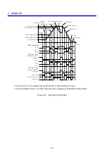
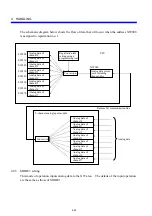
z
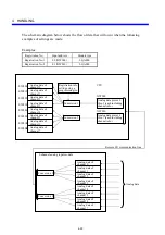
External output
z
Status code
R>C
R=C
R<C
R>C
R=C
R<C
Preset start
Latch reset
Count
stop
Latch reset
Count stop
Latch reset
Second preset value
Second compare value
First compare value
Third compare value
First preset value
(Operation mode 1)
Count stop
z
Status code
(Operation mode 2)
Count stop
Preset start
Compare value set
Latch reset
Compare
value set
Compare
value set
Start of
motor
forwarding
Start of motor reversing
Preset start
Compare value set
(*1)
Count value
Time
(*2)
(*1) If R=C is set, the status code is held at R=C until the latch is reset.
(*2) In operation mode 2, the flow designated by continuous dotted lines takes place.
Figure 4-9 Operation Flowchart
Summary of Contents for S10mini LQS070
Page 1: ......
Page 2: ......
Page 19: ...This Page Intentionally Left Blank ...
Page 30: ...1 BEFORE USE ...
Page 37: ...This Page Intentionally Left Blank ...
Page 38: ...2 KINDS AND SPECIFICATIONS OF I O MODULES ...
Page 57: ...This Page Intentionally Left Blank ...
Page 58: ...3 INDIVIDUAL SPECIFICATIONS ...
Page 143: ...This Page Intentionally Left Blank ...
Page 144: ...4 HANDLING ...
Page 179: ...This Page Intentionally Left Blank ...
Page 180: ...5 HANDLING I O DATA ON J NET ...
Page 186: ...6 HANDLING I O DATA ON D Station ...
Page 191: ...This Page Intentionally Left Blank ...
Page 192: ...7 MAINTENANCE ...


