4 HANDLING
4-22
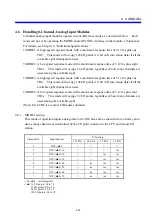
4.5 Handling 4-Channel Analog Input/Output Modules
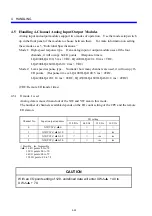
Analog input and output modules support two modes of operation. Use the mode setup switch
up in the front panel of the module to choose between them. For more information on setting
these modes, see 3, “Individual Specifications.”
Mode 1: High-speed response type. If an analog input or output module uses all the four
channels, it will occupy 64 I/O points. (Response time is:
LQA000/LQA100: 5 ms + TRC, LQA200/LQA201: 10 ms + TRC,
LQA500/LQA600/LQA610: 4 ms + TRC)
Mode 2: Low-speed response type. No matter how many channels are used, it will occupy 16
I/O points. (Response time is: LQA000/LQA100: 5 ms + 4TRC,
LQA200/LQA201: 10 ms + 4TRC, LQA500/LQA600/LQA610: 4 ms + 4TRC)
(TRC: Remote I/O transfer time)
4.5.1 If mode 1 is set
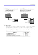
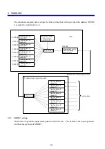
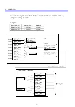
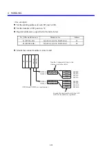
Analog data is moved in and out of the XW and YW area in this mode.
The number of channels available depends on the I/O count setting of the CPU and the remote
I/O station.
Channel No.
Input (output) address
I/O setting
128 I/Os
64 I/Os
32 I/Os
16 I/Os
0 XW(YW)
△▲
0
√
√
√
√
1 XW(YW)
△▲
0+10
√
√
√
im
2 XW(YW)
△▲
0+20
√
√
im
im
3 XW(YW)
△▲
0+30
√
√
im
im
√
: Possible im: Impossible
△▲
: 16 I/O points: 00 to 7F
32 I/O points: 00 to 7E
64 I/O points: 00 to 7C
128 I/O points: 00 to 78
CAUTION
With an I/O point setting of 128, undefined data will enter XW
△▲
+ 40 to
XW
△▲
+ 70.
Summary of Contents for S10mini LQS070
Page 1: ......
Page 2: ......
Page 19: ...This Page Intentionally Left Blank ...
Page 30: ...1 BEFORE USE ...
Page 37: ...This Page Intentionally Left Blank ...
Page 38: ...2 KINDS AND SPECIFICATIONS OF I O MODULES ...
Page 57: ...This Page Intentionally Left Blank ...
Page 58: ...3 INDIVIDUAL SPECIFICATIONS ...
Page 143: ...This Page Intentionally Left Blank ...
Page 144: ...4 HANDLING ...
Page 179: ...This Page Intentionally Left Blank ...
Page 180: ...5 HANDLING I O DATA ON J NET ...
Page 186: ...6 HANDLING I O DATA ON D Station ...
Page 191: ...This Page Intentionally Left Blank ...
Page 192: ...7 MAINTENANCE ...


