4 HANDLING
4-26
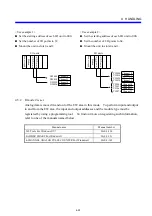
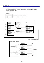
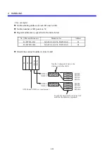
<Use example 1>
If you wish to use two channels:
z
Set the I/O address of the I/O unit to XW000.
z
Set the I/O point count to 32.
z
Mount LQA050 modules in slot nos. 0 and 1.
L
Q
A
0
5
0
XW000
XW010
XW020
XW030
Channel 0
Channel 1
Channel 0
Channel 1
I/O units
L
Q
A
0
5
0
Power supply
Station
4.6.2 MODE2
setting
This mode of operation writes analog data to the EW area and reads it from that area. To
input analog data to the EW area, you must register input addresses and module types with
your user system by using an appropriate programming tool. For details, refer to the
following manuals:
Manual name
Manual number
S10 Tools For Windows® V7
SAE-3-120
LADDER CHART For Windows®
SAE-3-121
Summary of Contents for S10mini LQS070
Page 1: ......
Page 2: ......
Page 19: ...This Page Intentionally Left Blank ...
Page 30: ...1 BEFORE USE ...
Page 37: ...This Page Intentionally Left Blank ...
Page 38: ...2 KINDS AND SPECIFICATIONS OF I O MODULES ...
Page 57: ...This Page Intentionally Left Blank ...
Page 58: ...3 INDIVIDUAL SPECIFICATIONS ...
Page 143: ...This Page Intentionally Left Blank ...
Page 144: ...4 HANDLING ...
Page 179: ...This Page Intentionally Left Blank ...
Page 180: ...5 HANDLING I O DATA ON J NET ...
Page 186: ...6 HANDLING I O DATA ON D Station ...
Page 191: ...This Page Intentionally Left Blank ...
Page 192: ...7 MAINTENANCE ...

