4 HANDLING
4-28
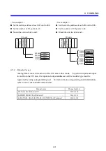
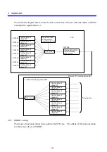
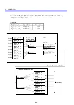
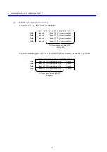
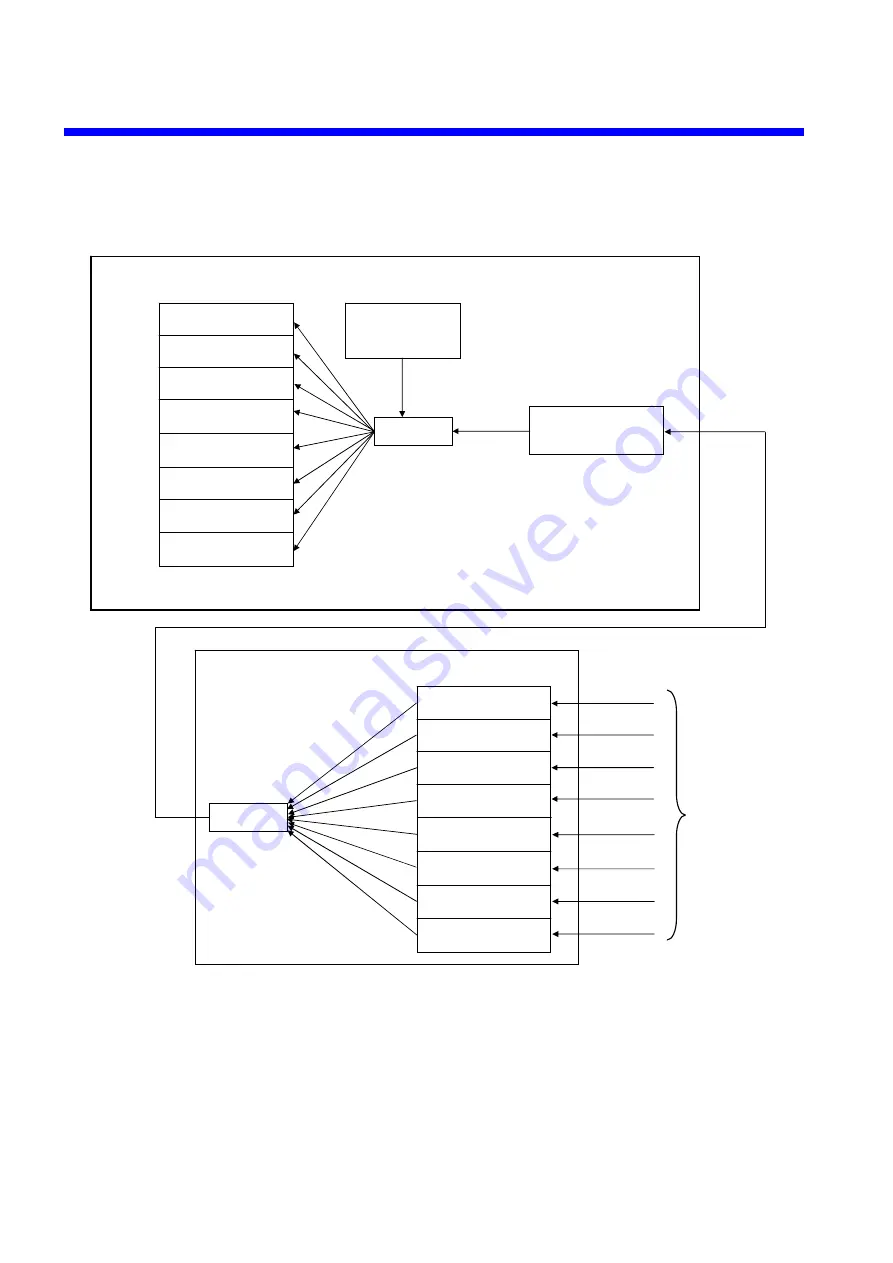
The schematic diagram below shows the flow of data that will occur when the address XW000
is assigned to registration no. 1.
4.6.3 MODE3
setting
This mode of operation inputs analog data to the XW area. The details of the input operation
are the same as those of MODE1.
Registration info
setting using a
programming tool
EW400
EW410
EW420
EW430
EW440
EW450
EW460
EW470
Analog data of
channel 0
Conversion
Analog data pieces
(each including
channel info)
XW000
8-channel analog input module
Remote I/O communication line
CPU
Analog data of
channel 1
Analog data of
channel 2
Analog data of
channel 3
Analog data of
channel 4
Analog data of
channel 5
Analog data of
channel 6
Analog data of
channel 7
Analog data of
channel 0
Analog data of
channel 1
Analog data of
channel 2
Analog data of
channel 3
Analog data of
channel 4
Analog data of
channel 5
Analog data of
channel 6
Analog data of
channel 7
Analog data
Conversion
Summary of Contents for S10mini LQS070
Page 1: ......
Page 2: ......
Page 19: ...This Page Intentionally Left Blank ...
Page 30: ...1 BEFORE USE ...
Page 37: ...This Page Intentionally Left Blank ...
Page 38: ...2 KINDS AND SPECIFICATIONS OF I O MODULES ...
Page 57: ...This Page Intentionally Left Blank ...
Page 58: ...3 INDIVIDUAL SPECIFICATIONS ...
Page 143: ...This Page Intentionally Left Blank ...
Page 144: ...4 HANDLING ...
Page 179: ...This Page Intentionally Left Blank ...
Page 180: ...5 HANDLING I O DATA ON J NET ...
Page 186: ...6 HANDLING I O DATA ON D Station ...
Page 191: ...This Page Intentionally Left Blank ...
Page 192: ...7 MAINTENANCE ...

