7 MAINTENANCE
7-4
7.2 Troubleshooting
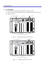
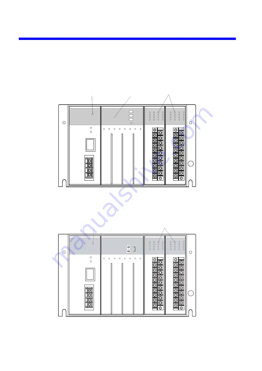
When a module fails, proceed with troubleshooting by following these steps:
(1) Check the status of LED illumination on the power supply module and the CPU indicator.
(2) Replace the module.
CPU unit (Two-slot mount base)
Operation indication LED
Indicating LEDs
Power supply module
CPU module
I/O modules
Indicators
HITACHI
S10mini
LQP000
LADDER
MODE
PROTECT
RESET
STOP
RUN
SIMU
NORM
OFF
ON
PS
LQV000
POWER
ON
OFF
H
N
LG
FG
100-120 VAC
5 VDC
GND
SERVICE
CHECK
POWER
D.INPUT
LQX100
100-120VAC
0
1
2
3
4
5
6
7
8
9
A
B
C
D
E
F
D.INPUT
LQX100
100-120VAC
0
1
2
3
4
5
6
7
8
9
A
B
C
D
E
F
CPU RUN
Figure 7-2 Troubleshooting Failures in the CPU Unit
I/O unit (Two-slot mount base)
Operation indication LED
Indicating LEDs
Power supply module
Station module
I/O modules
PS
LQV000
POWER
ON
OFF
H
N
LG
FG
100-120 VAC
5 VDC
GND
SERVICE
CHECK
POWER
D.INPUT
LQX100
100-120VAC
0
1
2
3
4
5
6
7
8
9
A
B
C
D
E
F
D.INPUT
LQX100
100-120VAC
0
1
2
3
4
5
6
7
8
9
A
B
C
D
E
F
LQS000
HITACHI
HSC-1000
RI/O
RI/O
U
L
ST.NO
Figure 7-3 Troubleshooting Failures in I/O Units
Summary of Contents for S10mini LQS070
Page 1: ......
Page 2: ......
Page 19: ...This Page Intentionally Left Blank ...
Page 30: ...1 BEFORE USE ...
Page 37: ...This Page Intentionally Left Blank ...
Page 38: ...2 KINDS AND SPECIFICATIONS OF I O MODULES ...
Page 57: ...This Page Intentionally Left Blank ...
Page 58: ...3 INDIVIDUAL SPECIFICATIONS ...
Page 143: ...This Page Intentionally Left Blank ...
Page 144: ...4 HANDLING ...
Page 179: ...This Page Intentionally Left Blank ...
Page 180: ...5 HANDLING I O DATA ON J NET ...
Page 186: ...6 HANDLING I O DATA ON D Station ...
Page 191: ...This Page Intentionally Left Blank ...
Page 192: ...7 MAINTENANCE ...

