3 INDIVIDUAL SPECIFICATIONS
3-22
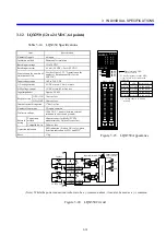
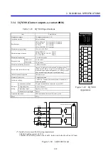
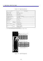
3.17 LQY160 (Contact outputs, a-contacts × 2, c-contacts × 4)
Table 3-21 LQY160 Specifications
Item Specification
Number of outputs
6 outputs (a-contacts × 2, c-contacts × 4) (*)
Insulation method
Relay insulation
Rated output
100 to 220 VAC: 2.0 A/output
12 to 24 VDC: 2.0 A/output
48 VDC:
0.5 A/output
100 to 110 VDC: 0.1 A/output
Maximum output voltage
250 VAC, 125 VDC
Minimum output current
100 to 220 VAC:
10 mA
48 VDC, 100 to 110 VDC: 10 mA
12 to 24 VDC:
20 mA
Maximum rush current
5 A, 100 ms or less
Response time
OFF
→
ON
15 ms or less
ON
→
OFF
15 ms or less
Maximum switching frequency 1,800
cycles/hour
Service life (electrical) of relay
Approx. 100,000 cycles of make-and-break operation (2 A
at 220 VAC [COS
φ
= 0.4], 2 A at 24 VDC [L/R = 7 ms],
make-and-break operation frequency of 1,800 cycles per
hour, normal temperature and normal humidity)
Internal current dissipation
320 mA or less
Number of commons
One input/common (independent common)
RY output enable signal
Rated input voltage, current
80 to 120 VAC/DC, approx. 10 mA
Dielectric voltage
1,500 VAC, 1 minute (between external terminals in a
batch and ground)
External
wiring
Connection method
18-point terminal block connector (screw: M3)
Compatible wire
0.3 to 1.25 mm
2
Tightening torque
Approx. 6 to 8 N
・
m
Allowable wiring length
200 m
Operation indication
LED indication (lit when a contact ON); color: green
Mass 250
g
(*) The address assignments are shown below.
0 1 2 3 4 5 6 7 8 9 A B C D E F
MSB LSB
無効
0
:
a5 OFF
1
:
a5 ON
0
:
a4 OFF
,
b4 ON
1
:
a4 ON
,
b4 OFF
0
:
a3 OFF
,
b3 ON
1
:
a3 ON
,
b3 OFF
0
:
a0 OFF
,
b0 ON
1
:
a0 ON
,
b0 OFF
0
:
a1 OFF
1
:
a1 ON
0
:
a2 OFF
,
b2 ON
1
:
a2 ON
,
b2 OFF
No effect
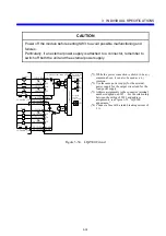
Fuse (*)
Output indication LED
Load
A1 COM0
RY
A2 a0
L
A3 b0
L
A4 COM1
A5 a1
L
RY
B7 COM5
B8 a5
A9 +V
L
B9 -V
RY
A6 COM2
RY
A7 a2
L
A8 b2
L
B1 COM3
RY
B2 a3
L
B3 b3
L
B4 COM4
RY
B5 a4
L
B6 b4
L
Filter
circuit
RY output enable signal input terminal
Control circuit
(*) Install a fuse to meet the following requirements:
y
Rated breaking current of 5 A
y
Install a fuse on the positive side of a DC load, or on both sides of an AC load.
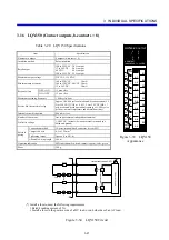
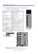
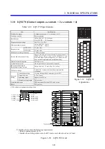
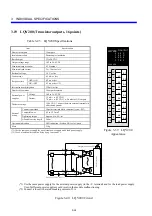
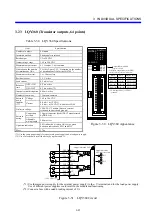
Figure 3-36 LQY160 Circuit
A1
A2
A3
A4
A5
A6
A7
A8
A9
B1
B2
B3
B4
B5
B6
B7
B8
B9
100-220 VAC, 12-24 VDC
LQY160
D.OUTPUT
3
2
1
0
5
4
b3
a3
3
b0
a0
0
b2
a2
2
a1
1
b4
a4
4
a5
+V
-V
5
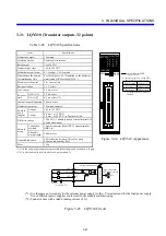
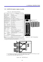
Figure 3-35 LQY160
Appearance
Summary of Contents for S10mini LQS070
Page 1: ......
Page 2: ......
Page 19: ...This Page Intentionally Left Blank ...
Page 30: ...1 BEFORE USE ...
Page 37: ...This Page Intentionally Left Blank ...
Page 38: ...2 KINDS AND SPECIFICATIONS OF I O MODULES ...
Page 57: ...This Page Intentionally Left Blank ...
Page 58: ...3 INDIVIDUAL SPECIFICATIONS ...
Page 143: ...This Page Intentionally Left Blank ...
Page 144: ...4 HANDLING ...
Page 179: ...This Page Intentionally Left Blank ...
Page 180: ...5 HANDLING I O DATA ON J NET ...
Page 186: ...6 HANDLING I O DATA ON D Station ...
Page 191: ...This Page Intentionally Left Blank ...
Page 192: ...7 MAINTENANCE ...

