7. Wiring
7-12
7.6 Wiring for external I/O signals of the RI/O-IF module
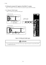
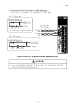
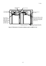
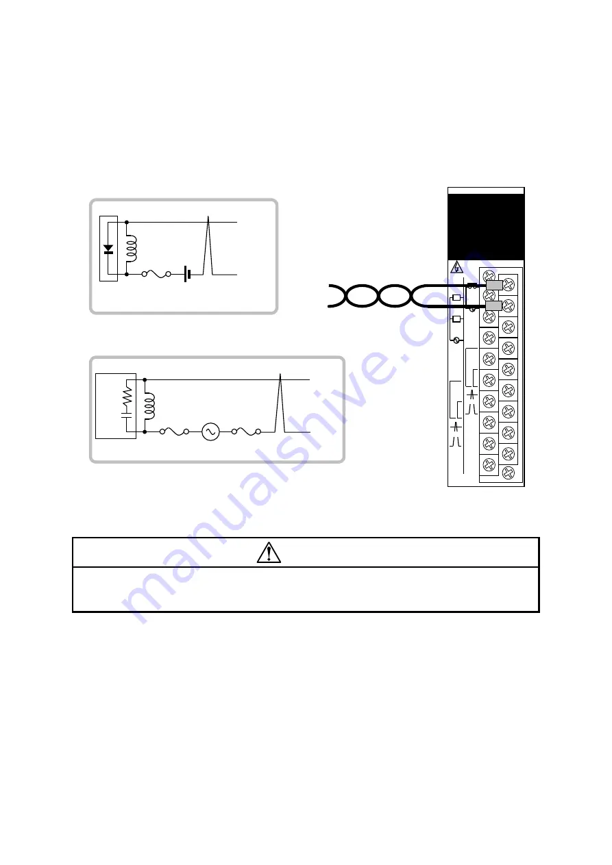
Figure 7-13 and Figure 7-14 show the wiring for the external I/O signals of the RI/O-IF module.
7.6.1 Wiring for PCsOK signal
Figure 7-13 shows the wiring for the PCsOK signal.
Figure 7-13 Wiring for PCsOK signal
WARNING
● To avoid fire, place fuses on both sides of the AC power supply. This protects the system if the PCsOK
or COM line shorts to FG.
LQE950
RI/O-IF
L
L
SHD
A
100VAC
100VDC
PCsOK
RI/O
STOP
STOP
/RUN
TERM
150
Ω
TERM
100
Ω
B
SHD
FG
SHD
RI/O2
A
B
RI/O1
TERM
150
Ω
TERM
100
Ω
SHD
100VAC
100VDC
12 V to 24 V DC/2 A
48 V DC/0.5 A
100 V DC/0.1 A
PCsOK
(B1)
Fuse
(5 A)
■ AC power supply
COM
(B2)
Coil
load
■ DC power supply
Surge-absorbing circuit
PCsOK
(B1)
Fuse
(5 A)
COM
(B2)
Coil
load
Surge-absorbing circuit
Fuse
(5 A)
100 V AC
R
0.1 μF
Twisted pair cable
(100 m or shorter)
PCsOK
COM
Summary of Contents for S10VE
Page 1: ...User s Manual General Description SEE 1 001 A ...
Page 2: ...User s Manual General Description ...
Page 53: ...This page is intentionally left blank ...
Page 59: ...This page is intentionally left blank ...
Page 67: ...This page is intentionally left blank ...
Page 75: ...This page is intentionally left blank ...
Page 77: ...This page is intentionally left blank ...
Page 103: ...This page is intentionally left blank ...
Page 129: ...This page is intentionally left blank ...
Page 295: ...This page is intentionally left blank ...
Page 309: ...This page is intentionally left blank ...
Page 341: ...This page is intentionally left blank ...
Page 345: ...This page is intentionally left blank ...
Page 475: ...This page is intentionally left blank ...
Page 489: ...This page is intentionally left blank ...
Page 505: ......

