7. Wiring
7-20
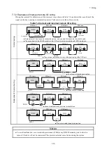
7.7.5 Connecting the remote I/O cable shields
This section explains how to connect the shields of the remote I/O cables that connect to RI/O-IF modules.
■ Connecting the shields of remote I/O cables
Connect the shields of the cables connected to remote I/O ports 1 and 2 to the respective SHD terminals on
the terminal block. The SHD terminals of remote I/O lines 1 and 2 have internal connections to the FG
terminals, and thus no external wiring is required between SHD and FG. Connect the FG terminal to the FG
terminal of the power supply module and the FG terminal of the mount base by using daisy-chain wiring.
■ Connecting cable shield leads for CPU status I/O cables
Connect the shield leads for the CPU state I/O cables to the respective SHD terminals on the terminal
block. The SHD terminals of CPU state I/O have internal connections to the FG terminals, and thus no
external wiring is required between SHD and FG. Connect the FG terminal to the FG terminal of the power
supply module and the FG terminal of the mount base by using daisy-chain wiring.
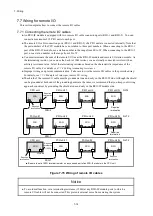
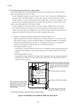
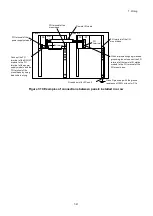
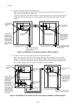
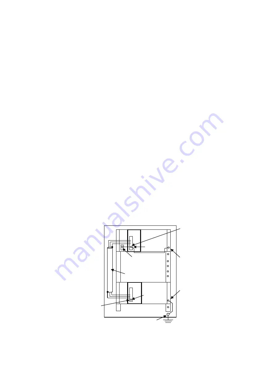
(1) Examples of connections in the same panel and between panels installed in a row
When connecting remote I/O cables in the same panel or in panels installed in a row, ground the shield
of the remote I/O cable at one end on the RI/O-IF module side. Although the shield can be grounded at
both ends if the grounding points are the same, we recommend that you keep your wiring approach
consistent by grounding the shield at one end only on the RI/O-IF module side.
● Grounding the shield at one end
Connect the FG terminal of the RI/O-IF module to the FG terminal of the power supply module and the
FG terminal of the mount base. Do not connect anything to the FG terminal of the remote I/O station
module.
● Grounding the shield at both ends
Connect the FG terminal of the RI/O-IF module to the FG terminal of the power supply module and the
FG terminal of the mount base. Connect the FG terminal of the remote I/O station module to the FG
terminal of the I/O mount base.
ST: Remote I/O station module, PS: Power supply module
Figure 7-18 Example of connections within the same panel
Panel
Class D grounding with the ground
resistance of 100Ω or less for PCs
ST
PS
PS
Remote I/O cable
FG terminal
FG terminal of the I/O mount base
Connect the FG terminal of the RI/O-IF
module to the FG terminal of the power
supply module and the FG terminal of
the mount base by using daisy-chain
wiring.
FG terminal of the mount base
When implementing single-ended
grounding, do not connect the FG
terminal of the remote I/O station
module to the FG terminal of the
I/O mount base.
RI/O
-IF
FG terminal
Ground point for PCs unit
FG terminal of
the power supply
module
Summary of Contents for S10VE
Page 1: ...User s Manual General Description SEE 1 001 A ...
Page 2: ...User s Manual General Description ...
Page 53: ...This page is intentionally left blank ...
Page 59: ...This page is intentionally left blank ...
Page 67: ...This page is intentionally left blank ...
Page 75: ...This page is intentionally left blank ...
Page 77: ...This page is intentionally left blank ...
Page 103: ...This page is intentionally left blank ...
Page 129: ...This page is intentionally left blank ...
Page 295: ...This page is intentionally left blank ...
Page 309: ...This page is intentionally left blank ...
Page 341: ...This page is intentionally left blank ...
Page 345: ...This page is intentionally left blank ...
Page 475: ...This page is intentionally left blank ...
Page 489: ...This page is intentionally left blank ...
Page 505: ......

