7. Wiring
7-23
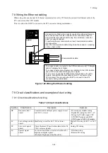
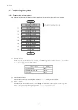
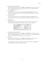
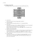
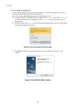
7.8 Wiring the Ethernet cabling
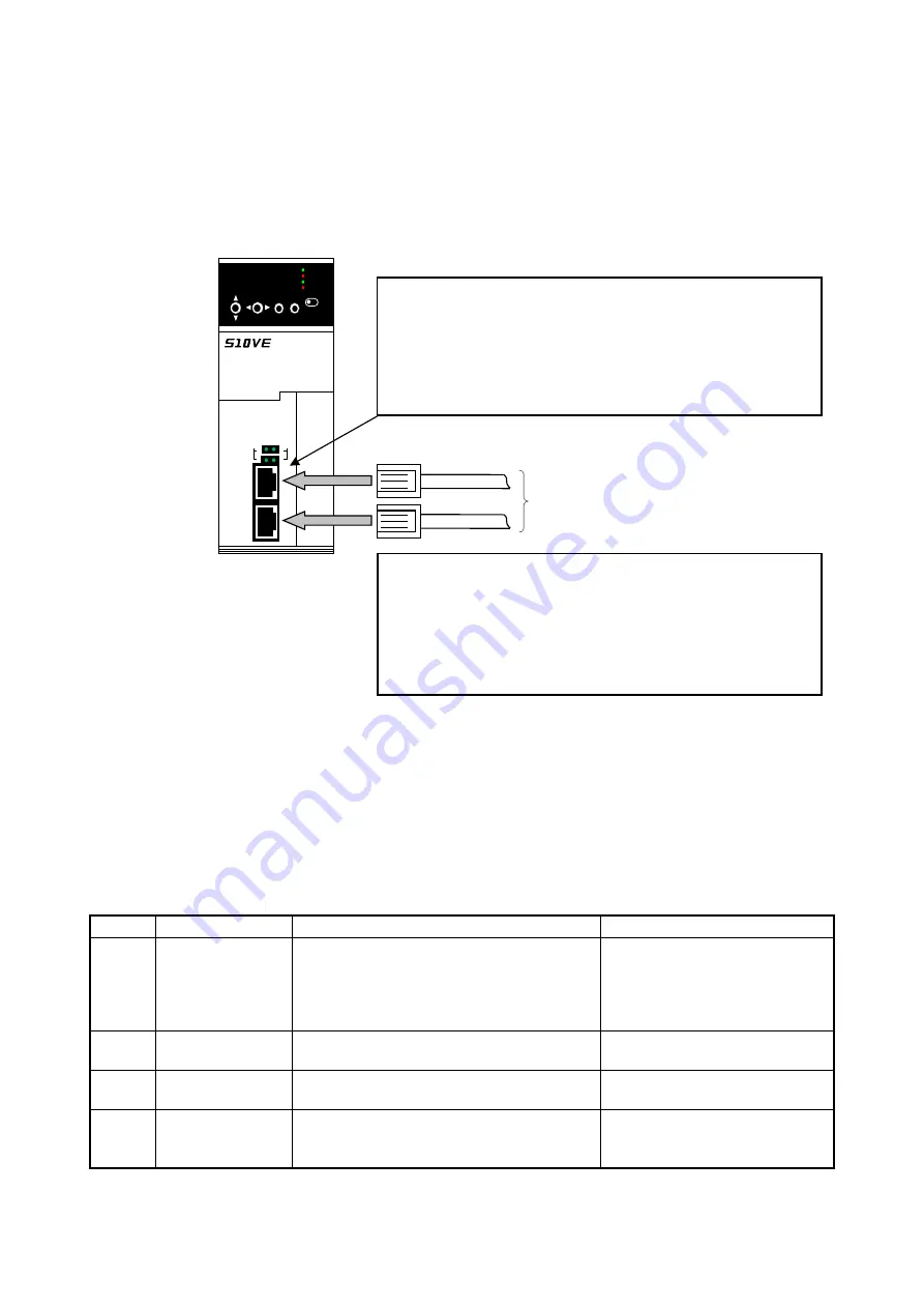
When using only one channel for Ethernet communication in the CPU module, connect the Ethernet cable to the
ET1 connector of the CPU module.
This is to allow the PADT to connect to the ET2 connector during maintenance.
Figure 7-22 Wiring the Ethernet cabling
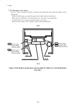
7.9 Circuit classifications and examples of duct wiring
7.9.1 Circuit classifications for wiring
Table 7-6 Circuit classifications
Symbol
Classification
Description
Example
HC
General control
circuit
Control circuit and input power supply circuit
for 250 V or lower
- Power supply module wiring
- Digital I/O wiring for 100 V AC
- Wiring for PCsOK signal, CPU
STOP/RUN signal, and RI/O
STOP signal of RI/O-IF module
LC
Low-voltage control
circuit
Small relay circuit for 60 V DC or lower
Digital I/O wiring for 48 V or 24 V
DC
LT
Low-level signal
circuit
Circuit that uses ICs and other elements for 24
V DC or lower signals
Analog I/O wiring
LS
Special signal
circuit
Low noise-resistance circuit such as those for
high-speed digital signals
(Example: High-speed bus line cable)
- Ethernet wiring
- Remote I/O wiring
ALARM
ET2
ET1
2
1
ACT
1
2
LINK
LQP600
CPU
RU
N
STOP
ERR
STBY
RUN
LADDER
SET
ESC
L
R
UP
DW N
C
P
U
R
U
N
Communication cable.
- Connectors are fitted with connector caps before shipping. Remove
the connector cap from the connector of the channel you want to
use. Store the removed connector cap. Do not remove connector
caps for unused channels.
- To perform Ethernet communication, insert communication cables
into connectors.
- Insert the communication cable straight into the connector, pressing
until you hear a click.
- To connect a hub or a router to the CPU module, use a UTP straight
cable of category 5e or higher.
- To connect a personal computer or an indicator to the CPU module,
use a UTP cross cable of category 5e or higher.
- To use only one channel for Ethernet communication in the CPU
module, connect the Ethernet cable to the ET1 connector of the
CPU module. This is to allow the PADT to connect to the ET2
connector during maintenance.
Summary of Contents for S10VE
Page 1: ...User s Manual General Description SEE 1 001 A ...
Page 2: ...User s Manual General Description ...
Page 53: ...This page is intentionally left blank ...
Page 59: ...This page is intentionally left blank ...
Page 67: ...This page is intentionally left blank ...
Page 75: ...This page is intentionally left blank ...
Page 77: ...This page is intentionally left blank ...
Page 103: ...This page is intentionally left blank ...
Page 129: ...This page is intentionally left blank ...
Page 295: ...This page is intentionally left blank ...
Page 309: ...This page is intentionally left blank ...
Page 341: ...This page is intentionally left blank ...
Page 345: ...This page is intentionally left blank ...
Page 475: ...This page is intentionally left blank ...
Page 489: ...This page is intentionally left blank ...
Page 505: ......

