background image

8. Tools 

8-6 

8.2.3.2 Installing individual tools 

You can install tools from a CD or from the basic installation set. The following explains how to install 

tools from the HI-FLOW SYSTEM/S10VE installation CD. 

Log on as an account with administrator privileges when installing the tools. 
(1)  To install the HI-FLOW SYSTEM/S10VE tool, double-click 

setup.exe

 in the folder 

S789803

 on 

the HI-FLOW SYSTEM/S10VE installation CD. The 

setup.exe

 file of each tool is located in a 

different folder. 

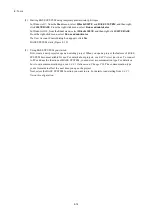
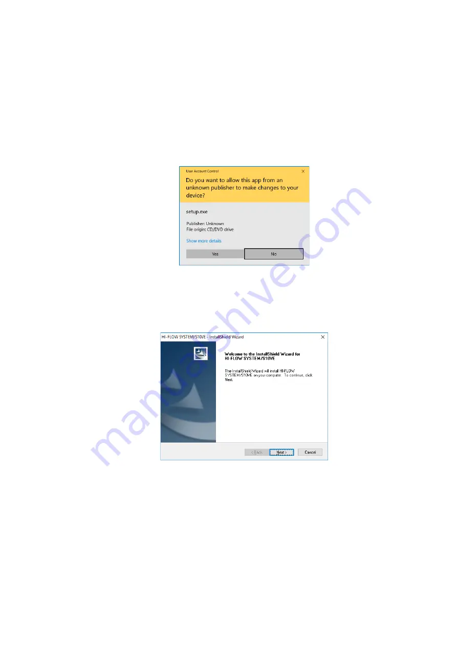
(2)  When you double-click 

setup.exe

, the following message might appear. Click 

Yes

 to acknowledge 

the message and begin the setup process. 


Figure 8-1 User Account Control message


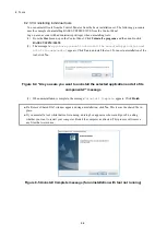
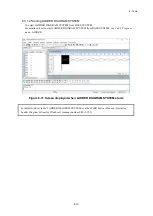
(3)  The InstallShield Wizard window appears. Install the tool as prompted by the messages in the 

installer. 


Figure 8-2 InstallShield Wizard window


Summary of Contents for S10VE

Page 1: ...User s Manual General Description SEE 1 001 A ...

Page 2: ...User s Manual General Description ...

Page 3: ...larification please contact your Hitachi sales representative Edition 1 October 2019 SEE 1 001 A No part of this material may be reproduced in any form or by any means without permission in writing from the publisher Information in this document is subject to change without notice For inquiries about this product please visit the following URL https www hitachi com s10 All Rights Reserved Copyrigh...

Page 4: ...injury and property damage or loss not related to personal injury used in the safety labels Serious injury Is an injury that has aftereffects and requires hospitalization for medical treatment or long term follow up care Examples of serious injuries are as follows vision loss burns caused by dry heat low temperature burns electric shock injuries broken bones and poisoning Minor or moderate injury ...

Page 5: ...ales staff The hazard warnings on the machine and in the manual cannot cover every possible case as it is impossible to predict and evaluate all circumstances You must be alert and use your common sense Do not perform any installation wiring handling or internal customization that is not described in this manual Hitachi will not be responsible for any damage to Hitachi equipment or peripherals and...

Page 6: ... maintenance area neat and tidy Make sure that maintenance parts materials and removed parts are not placed in a passageway so they are not tripped on by personnel Wear eye protection if there is a risk of flying debris When using sharp objects or cutting tools keep fingers and other parts of your body away from the path of the blade bit or point After maintenance work is completed before turning ...

Page 7: ...o ensure that the power is off Some parts in the machine remain charged for a certain time even after the power supply to the machine is disconnected Follow the displayed instructions When working on a machine which has a grounding terminal make sure that the terminal is properly connected to the facility s ground When working near an exposed live electric circuit do not work alone Work with anoth...

Page 8: ...nt by using a nonconductive object such as a dry wooden stick Call an ambulance If the victim is unconscious artificial respiration may be necessary A proper method for performing artificial respiration or resuscitation should be learned beforehand If the victim s heart is not beating cardio pulmonary resuscitation must be performed by a trained and qualified person In the case of fire Call the fi...

Page 9: ...ause electric shock or accident Turn off the power supply module before performing these tasks Check the wiring carefully before turning on the system Improper wiring can result in electric shock or fire Incorrect use of the system can lead to accidents and equipment damage Check the safety of peripheral equipment before modifying a running program or performing RUN or STOP operations See page 1 5...

Page 10: ...STOP RUN or COM line shorts to FG See page 7 13 To avoid electric shock do not touch the terminal block terminals or connector pins while the power is on To avoid electric shock and fire wiring must be carried out by a person with practical experience who has undergone the appropriate training and is able to recognize the hazards presented by the work To avoid electric shock accident or malfunctio...

Page 11: ...t cause such a connection to occur Do not remove multiple batteries from their packaging and store them stacked together If the primary battery shorts out a significant overcurrent might flow causing such issues as deformation leakage heat generation explosion or fire Do not directly solder terminals or wires to the primary battery The applied temperature can damage the insulation or internal stru...

Page 12: ... of metal When disposing of primary batteries use insulating tape to wrap each battery as shown in the following example Having done so dispose of the battery as industrial waste Example of battery insulation See page 14 7 To avoid electric shock turn off the power supply on the facility side that is connected to the PI O module before removing or mounting the module See page 14 25 Insulating tape...

Page 13: ... securely tightened Failing to do so can cause smoke fire or malfunction or cause the module to fall See pages 6 8 and 12 3 Do not allow ultrasonic wave vibration near the primary battery Ultrasonic wave vibration can pulverize its contents causing an internal short This can lead to issues as deformation leakage heat generation explosion or fire Do not handle the primary battery roughly Do not dro...

Page 14: ...on holes in the door and top panel or have a fan installed in the door To improve airflow within the cabinet make sure that there are gaps at the top bottom and sides of each mount base Failing to provide these gaps might lead to module failure or malfunction To avoid failure and malfunction consider the following measures during installation design to ensure that the intake air temperature at the...

Page 15: ...s with respect to the entire system configuration This allows you to identify the location of the fault when an issue with data occurs at the application level such as data not being updated due to a timeout The CPU module of the S10VE system does not perform external notification if the remote I O line times out It is the responsibility of the user to use a program that monitors the system regist...

Page 16: ...t If you are unable to provide 100 mm of clearance make sure that the intake air temperature will not exceed 55 C To avoid failure or malfunction leave clearance of at least 50 mm between the cabinet side panels and units If you are unable to provide 50 mm of clearance make sure that the intake air temperature will not exceed 55 C See page 6 4 Secure the mount base to the upright surface inside th...

Page 17: ... module observe the following precautions when mounting or removing the module Before mounting the module on the mount base connector check that the connector pins are properly aligned and not bent broken or soiled Connecting or disconnecting a module that is tilted might damage connector pins When moving the module hold it vertically parallel to the mount base as shown below See page 6 8 Mounting...

Page 18: ...from short circuits provide fuses or circuit protectors in any external power source Use a circuit protector that is appropriate for the rating of the system Surge voltage can cause equipment damage or malfunction If you connect a coil such as a relay to the PCsOK output circuit you must also provide a surge absorption diode or other means to protect from surge voltage This diode must withstand re...

Page 19: ... to the system with an administrator account BASE SYSTEM S10VE might not be installed properly in any of the following cases 1 Administrator permissions are acquired by using User Account Control from a standard user account 2 The administrator account was created from a standard user account by using User Account Control In this case log on with the administrator account that was first created on...

Page 20: ...or less See page 12 1 Static electricity might damage a module or cause it to malfunction Discharge any static electricity from your body before touching the equipment See pages 12 3 14 10 14 13 14 16 14 19 14 22 14 25 and 14 27 Take care to tighten the screws securely Failing to do so can result in the system stopping or malfunctioning or cause a module to fall To avoid malfunction make sure that...

Page 21: ...might not be installed or uninstalled correctly Exit all Windows programs before installing each tool This includes memory resident programs such as anti virus software An error might occur if you attempt to install a tool with other programs still running In this case uninstall the tool you were installing and exit all Windows programs Then install the tool again For details on how to uninstall a...

Page 22: ...ation leakage overheating explosion or fire Do not charge the battery Do not vibrate or shock the battery Follow the instructions in the manual for the use of the battery 警告 WARNING ケーブル挟み込み注意 Do not put the cables between cases Type HDC5200 Hitachi Ltd 警告 WARNING LQV410 PS HITACHI 100 120VAC 144VA 50 60Hz 100 110VDC 132W FG H N OFF ON P O W E R INPUT 100 120VAC 100 110VDC 感電危険触れるな Hazardous volta...

Page 23: ...S 20 RI O IF module LQE950 LQE950 RI O IF L L SHD A 100VAC 100VDC PCsOK RI O STOP STOP RUN TERM 150Ω TERM 100Ω B SHD FG SHD RI O2 A B RI O1 TERM 150Ω TERM 100Ω SHD 100VAC 100VDC ...

Page 24: ... lift facility facility for recreation and amusement medical facility safety equipment on vehicle equipment ship facility traffic light system and other facilities where death or bodily harm might result in the event of an emergency Applications where a high level of responsibility is required Example Systems that supply gas water or electricity systems requiring round the clock operation system r...

Page 25: ...pair is limited to replacement of malfunctioning parts Work other than replacement of malfunctioning parts such as investigation into the cause of failure shall be charged even during the warranty period 2 Exception of warranty obligation Regardless of the warranty period Hitachi bears no responsibility in any of the following cases The warranty mentioned here means the warranty for the individual...

Page 26: ...ichever comes earlier The standard service life of S10VE is 10 years We cannot accept repair of products whose designated repair acceptance periods as described here have been exceeded Payment for any repair after expiration of the warranty is the responsibility of the customer 5 Service after production of the product is stopped Products including spare parts cannot be supplied after production o...

Page 27: ...S 24 Revision History Revision No History revision details Issue date Remarks A New edition Oct 2019 ...

Page 28: ...idual modules 4 Using the S10VE System This chapter lists the procedures related to use of the S10VE system and points to where in this manual each procedure is explained 5 Part Names and Functions This chapter explains the name and function of each part of the S10VE system and describes its external dimensions 6 Installation This chapter explains how to install the S10VE equipment in the panel an...

Page 29: ...mark of Fuji Xerox Co Ltd Other company and product names mentioned in this document may be the trademarks or registered trademarks of their respective owners This manual sometimes omits the or symbol Note about storage capacity calculations Memory capacities and requirements file sizes and storage requirements must be calculated according to the formula 2n The following examples show the results ...

Page 30: ...122 S10VE Software Manual Programming HI FLOW for Windows SEE 3 131 S10VE Software Manual Operation Ladder Diagram System for Windows SEE 3 132 S10VE Software Manual Operation HI FLOW for Windows SEE 3 133 S10VE Software Manual Operation RPDP for Windows SEE 3 134 S10VE Software Manual Operation NXACP For Windows SEE 3 137 S10VE Software Manual Operation NXTOOLS SYSTEM For Windows SEE 3 201 S10VE ...

Page 31: ... HI FLOW SYSTEM S10VE A tool for creating modifying monitoring and debugging HI FLOW application programs that run on the S10VE BACKUP RESTORE SYSTEM S10VE A tool for backing up and restoring data on the CPU module PADT An abbreviation for Programming And Debugging Tools The PADT is the PC that runs BASE SYSTEM S10VE and other package software CPMS An abbreviation for Compact Process Monitor Syste...

Page 32: ... Names and Functions 5 1 5 1 Mount base HSC 1770 5 1 5 2 Power supply module LQV410 5 3 5 3 CPU module LQP600 5 5 5 4 RI O IF module LQE950 5 9 6 Installation 6 1 6 1 Operating environment 6 1 6 2 Grounding 6 1 6 3 Grounding the cabinets 6 2 6 4 Mounting clearances 6 4 6 5 External dimensions of mount base 6 5 6 6 Attaching the mount base 6 6 6 7 Attaching modules 6 7 6 8 Connecting the primary ba...

Page 33: ... 5 Connecting the remote I O cable shields 7 20 7 8 Wiring the Ethernet cabling 7 23 7 9 Circuit classifications and examples of duct wiring 7 23 7 9 1 Circuit classifications for wiring 7 23 7 9 2 Example of duct wiring 7 24 7 10 Working with connector caps 7 25 8 Tools 8 1 8 1 Notes on tool usage 8 1 8 1 1 Overview of tools 8 1 8 1 2 Hardware and software requirements 8 1 8 1 3 Restrictions on c...

Page 34: ... Close 8 28 8 4 2 4 Project menu Delete 8 29 8 4 2 5 Project menu Set Network 8 31 8 4 2 5 1 Network configuration of CPU built in Ethernet 8 32 8 4 2 5 2 ET NET configuration 8 36 8 4 2 6 Project menu Download CPMS 8 47 8 4 2 7 Project menu End 8 50 8 4 3 Online functions 8 51 8 4 3 1 Online menu Change PCs 8 52 8 4 3 2 Online menu Display PCs STATUS and Change PCs STATUS 8 53 8 4 3 3 Online menu...

Page 35: ... 8 4 7 CPMS debugger functions 8 110 8 4 7 1 CPMS Debugger menu Task Abort 8 111 8 4 7 2 CPMS Debugger menu Display Task Status 8 112 8 4 7 3 CPMS Debugger menu Initialize Task 8 114 8 5 BACKUP RESTORE SYSTEM 8 117 8 5 1 Backup 8 117 8 5 2 Restore 8 126 8 5 3 Backup save data comparison 8 133 8 5 4 Duration of backup restoration processes 8 139 8 5 5 Scope of backup restoration and comparison 8 14...

Page 36: ...on of displayed information 10 5 10 4 1 Home position display 10 5 10 4 2 Firmware version display 10 7 10 4 3 OS version display 10 7 10 4 4 CPU module error status display 10 8 10 4 5 Indicator pattern display available when CPU module is in STOP mode 10 10 10 4 6 Ladder mode display extended menu 10 11 10 4 7 PCs number display extended menu 10 12 10 4 8 Display of E coils in ON mode extended m...

Page 37: ...1 2 CPU module model LQP600 13 3 13 2 Troubleshooting individual modules 13 14 13 2 1 CPU module troubleshooting 13 14 13 2 2 Troubleshooting optional modules 13 20 13 2 2 1 OD RING module troubleshooting 13 20 13 2 2 2 J NET module troubleshooting 13 33 13 2 2 3 D NET module troubleshooting 13 43 13 2 2 4 FL NET module troubleshooting 13 46 13 2 2 5 ET NET module troubleshooting 13 50 13 2 3 Remo...

Page 38: ...ING module 14 10 14 4 2 Installing an OD RING module 14 11 14 4 3 Adding an OD RING module 14 12 14 5 J NET module LQE540 E 14 13 14 5 1 Removing the J NET module 14 13 14 5 2 Installing a J NET module 14 14 14 5 3 Adding a J NET module 14 15 14 6 D NET module LQE770 E 14 16 14 6 1 Removing the D NET module 14 16 14 6 2 Installing a D NET module 14 17 14 6 3 Adding a D NET module 14 18 14 7 FL NET...

Page 39: ... 14 27 14 10 1 Removing the remote I O optical adapter module 14 27 14 10 2 Installing a remote I O optical adapter module 14 28 14 11 Backup and restoration 14 29 14 11 1 Backup procedure 14 29 14 11 2 Restoration procedure 14 29 14 12 Disposal 14 29 ...

Page 40: ...Checking version and revision numbers of installed software products C 5 C 5 Uninstalling software products C 6 C 6 Installing software products and checking the installed version and revision numbers C 8 C 7 Replacing CPMS S10VE in existing projects C 10 C 8 Setting the connection target PCs C 12 C 9 Checking current version and revision numbers of CPMS S10VE on actual machines C 13 C 10 Download...

Page 41: ...ts to ground multiple cabinets in a row 6 2 Figure 6 3 Example of base insulation 6 2 Figure 6 4 Unit mounting clearances 6 4 Figure 6 5 External dimensions of S10VE 6 5 Figure 6 6 Attaching the mount base 6 6 Figure 6 7 Attaching a module 6 7 Figure 6 8 Primary battery connection procedure 6 9 Figure 6 9 External view of mount base 6 10 Figure 7 1 18 point terminal block 7 3 Figure 7 2 11 point t...

Page 42: ...ion and all of its components message 8 8 Figure 8 5 Uninstall Complete message for uninstallation with tool not running 8 8 Figure 8 6 Uninstall Complete message for uninstallation of running tool 8 9 Figure 8 7 Error message displayed by RPDP internal command 8 9 Figure 8 8 User Account Control message basic installation set 8 10 Figure 8 9 Setup window basic installation set 8 11 Figure 8 10 Sc...

Page 43: ...sage 8 39 Figure 8 43 Open window Set Network ET NET 8 40 Figure 8 44 File open window 8 41 Figure 8 45 Wrong file selected message 8 41 Figure 8 46 Option module parameter setup list window deletion 8 42 Figure 8 47 Confirm deletion message 8 42 Figure 8 48 Save As dialog box 8 43 Figure 8 49 File save window 8 44 Figure 8 50 Error message when connected to ET NET module 8 47 Figure 8 51 Download...

Page 44: ...9 Data deletion confirmation message 8 67 Figure 8 80 Remote reset confirmation message 8 68 Figure 8 81 Remote restart confirmation message 8 69 Figure 8 82 Restart successful message 8 69 Figure 8 83 Restart failed message 8 69 Figure 8 84 Data clear confirmation message 8 70 Figure 8 85 Error detected message 8 71 Figure 8 86 Window after clicking the Program menu 8 72 Figure 8 87 Setting Tool ...

Page 45: ... data cannot be read 8 115 Figure 8 121 Progress window initializing task environment 8 115 Figure 8 122 CPU stop confirmation message for backup function 8 117 Figure 8 123 Backup window 8 118 Figure 8 124 Browse For Folder dialog box 8 118 Figure 8 125 Overwrite confirmation message 8 119 Figure 8 126 State of backup window when receiving data 8 119 Figure 8 127 Backup cancelation confirmation m...

Page 46: ...son window when outputting comparison error data file 8 136 Figure 8 157 Confirmation message for overwriting comparison error data file 8 137 Figure 8 158 Areas subject to ROM load operation 8 140 Figure 8 159 Format of operation record file 8 143 Figure 10 1 Indicator and menu keys 10 1 Figure 10 2 Indicator display transitions when CPU module is in STOP mode 10 3 Figure 10 3 Indicator display t...

Page 47: ...ack frame 13 36 Figure 13 15 Address of the error accumulation counters 13 40 Figure 13 16 Structure of the trace area 13 41 Figure 13 17 Structure of the trace data area 13 42 Figure 13 18 Troubleshooting procedure 13 50 Figure 13 19 Failed parts in an example system configuration 13 51 Figure 13 20 Troubleshooting procedure for the PI O unit 13 84 Figure 13 21 Troubleshooting procedure for the r...

Page 48: ...ion of J NET module 14 14 Figure 14 7 Parts involved in replacement or addition of D NET module 14 17 Figure 14 8 Parts involved in replacement or addition of FL NET module 14 20 Figure 14 9 Parts involved in replacement or addition of ET NET module 14 23 ...

Page 49: ...e 6 1 Restrictions on number of option modules 6 11 Table 6 2 Restrictions on number of PI O modules 6 14 Table 6 3 Current consumption calculation table 6 15 Table 7 1 Cable specifications 7 2 Table 7 2 Recommended cables 7 2 Table 7 3 List of ground wiring requirements 7 9 Table 7 4 Correct and incorrect remote I O wiring 7 15 Table 7 5 Setting terminating resistance 7 18 Table 7 6 Circuit class...

Page 50: ...8 27 Properties window 8 150 Table 8 28 Project List window Open 8 151 Table 8 29 Project List window Delete 8 152 Table 8 30 Close 8 152 Table 8 31 Set Network window 8 152 Table 8 32 Download CPMS window 8 153 Table 8 33 End 8 154 Table 8 34 Change PCs window 8 155 Table 8 35 Display PCs STATUS and Change PCs STATUS 8 156 Table 8 36 Data Send Receive window 8 156 Table 8 37 Backup Restore and Ba...

Page 51: ... 11 6 Table 11 3 S10VE state list 11 10 Table 12 1 Limited life components and replacement cycle 12 1 Table 12 2 Check items 12 2 Table 13 1 Diagnosing problems by visually confirming the power supply module LEDs 13 2 Table 13 2 Diagnosing problems by visually confirming the CPU module LEDs 13 3 Table 13 3 CPU module troubleshooting 13 4 Table 13 4 OD RING module troubleshooting 13 6 Table 13 5 FL...

Page 52: ...ce information 13 65 Table 13 33 Count information 13 76 Table 13 34 Check items for when a failure occurs repeatedly 13 88 Table 13 35 Analyzing failures from the station module LEDs 13 89 Table 13 36 Analyzing failures from remote I O optical adapter LEDs 13 90 Table 13 37 Check items for when a failure occurs intermittently 13 91 Table 13 38 Failure analysis when a failure occurs intermittently...

Page 53: ...This page is intentionally left blank ...

Page 54: ...re 1 1 PCs means the programmable controllers in their entirety including the CPU unit and PI O units Use the S10VE in an environment that is within the specifications explained in Chapter 3 To ensure long term stable operation we recommend that you use the product at room temperature and normal relative humidity 15 to 35 C and 45 to 85 RH Using the product in a high temperature or high humidity e...

Page 55: ...ilding that provides at least class D grounding with the ground resistance of 100Ω or less Conditions for grounding to the steel frame of a building The steel frame is welded together The grounding between the earth and the steel frame meets the criteria for class D If this is not achievable ground the PCs panel by connecting it to a grounding rod driven into the earth This provides a low groundin...

Page 56: ...Disassembling modules Do not disassemble the modules Removing inserting modules You must turn off the power before removing or inserting a module To prevent module damage due to static electricity discharge any static electricity from your body before touching the equipment Installation of new equipment When peripheral equipment is added or replaced check the following aspects of the power supply ...

Page 57: ...re its ground cable with other equipment Make sure that no power or lead cables are positioned too closely to a signal cable such as a remote I O cable Figure 1 5 Grounding method Shared ground cable Other equipment S10VE S10VE Separate ground cables Other equipment ...

Page 58: ...usual odor turn off the power immediately and investigate the source Do not obstruct the ventilation slots at the top and bottom of the modules Doing so might cause smoke or fire or lead to module failure or malfunction The modules have open ventilation slots at the top and bottom To avoid smoke fire and module failure or malfunction take the necessary measures to prevent objects from falling into...

Page 59: ...This page is intentionally left blank ...

Page 60: ...can connect to HSC 1000 and HSC 2100 PI O units using remote I O lines A given system can incorporate both HSC 1000 and HSC 2100 PI O units Figure 2 1 Example system configuration S10 2α S10V S10 mini Duplexed ring maximum 64 nodes JPCN 1 device JPCN 1 device JPCN 1 device JPCN 1 device Channel 1 Channel 2 PI O unit PS DST I O I O PI O unit PS DST I O I O Max 63 units per channel Max 63 units per ...

Page 61: ... DC 5V 10V 1 5V C0 SHD SV1 C1 SHD SV2 C2 SHD SV3 C3 SHD 4 MODE RANGE 1 2 NOT USED NOT USED NOT USED NOT USED NOT USED Power supply module required RI O IF module optional CPU module required Option modules PI O modules I O modules optional PS slot IF slot CPU slot I O slots Mount base FG PR SR TX RX TX LQE510 E OD RING PR TR RX ERR SR TR RX ERR CPL No MODU No U L RX LQE770 E D NET MODU No MS NS CH...

Page 62: ...ax 12 units per channel CPU RI O IF PS S10VE CPU unit PI O unit PS ST RI O RI O opti cal ADP I O PI O unit PS ST RI O RI O opti cal ADP I O PI O unit PS ST RI O I O I O Max 12 units per channel PI O unit PS ST RI O RI O opti cal ADP I O PI O unit PS ST RI O RI O opti cal ADP I O PI O unit PS ST RI O I O I O Remote I O channel 1 Remote I O channel 2 Specifications for remote I O communication by RI...

Page 63: ...e Design the system in a way that considers fault analysis through such means as centralized installation and PI O unit aggregation Prepare an allocation table that shows the correspondence of I O signals and PI O addresses with respect to the entire system configuration This allows you to identify the location of the fault when an issue with data occurs at the application level such as data not b...

Page 64: ...se HSC 1770 A 7 slot mount base for the S10VE A maximum of seven modules option modules and I O modules can be mounted on the mount base These include the power supply module CPU module RI O IF module option modules and HSC 1000 PI O modules 2 Power supply LQV410 Input 100 to 120 V AC 100 to 110 V DC Output 5 V DC 10 A 3 CPU LQP600 The CPU module for the S10VE 4 RI O IF LQE950 The remote I O inter...

Page 65: ...s and vice versa 11 PI O LQX130 Digital input module 100 V AC contact input 16 points 12 LQX200 Digital input module 12 to 24 V DC contact input 16 points 13 LQX240 Digital input module 100 V DC contact input 16 points 14 LQX300 Digital input module 12 to 24 V DC contact input 32 points 15 LQX350 Digital input module 12 to 24 V DC contact input 64 points 16 LQY100 Digital output module relay conta...

Page 66: ...wing manual S10mini Hardware Manual OPT D NET manual number SME 1 120 2 3 3 PADT PADT Programming and Debugging Tools is a programming tool used to make test run and troubleshoot application programs for the S10VE system The PADT is a personal computer with the required software such as BASE SYSTEM S10VE installed The required specifications for the personal computer that serves as the PADT are as...

Page 67: ...This page is intentionally left blank ...

Page 68: ...ith the ground resistance of 100Ω or less Ambient air Dust 0 1mg m3 or less Corrosive gas JEITA IT 1004A Class B The environment must be free of corrosive gas Altitude 1 000 m or below Radioactivity The environment must be free of radioactivity Cooling Natural air cooling Weights Mount base HSC 1770 1 300 g or less Power supply module LQV410 1000 g or less CPU module LQP600 450 g or less RI O IF m...

Page 69: ...50 60 5 Hz 100 to 110 V DC Input voltage range 85 to 132 V AC 85 to 143 V DC Input voltage waveform distortion AC input 10 or less DC input 5 or less Input current AC100 120V 1 2A maximum DC100 110V 1 2A maximum Allowable momentary power interruption time AC85 132V 10ms or less DC85 143V 10ms or less Power consumption AC100 120V 144VA DC100 110V 132W Rush current 13 A or less 1 85 to 132 V AC 85 t...

Page 70: ...se Data for various programs such as user programs Size Bit area 2 MB Word area 1 MB including 0 5 MB backup area Backup Available 10 years Error correction ECC Backup memory Use Backup memory for user programs written in C Size 1 MB Backup Available 10 years Error correction ECC Ladder program memory Backup Available Size 512 k steps Processing speed Bit operations 9 4 ns at peak Peak performance...

Page 71: ...ing edge or falling edge can be selected System register S 49 152 points Operation result flags blown fuses timeouts etc Internal work register A J Q M 4 096 points A J 65 536 points Q M Data register DW 4 096 points 1 point 1 word 16 bits Data register BD 512 points 1 point 1 long word 32 bits Work register FW 3 072 points 1 point 1 word 16 bits Data register LB 65 536 points Data register LL 8 1...

Page 72: ...ation Dielectric strength withstand voltage 1500 V AC 1 minute Clock Functions Year month day hour minute second day of week No more than 4 seconds per day ambient temperature 0 to 55 C Time retained during power outage Yes guaranteed for 5 years The clock needs to be set again after battery replacement Hot swapping Not supported Current consumption 3 100 mA or less Startup time Power ON 50 second...

Page 73: ...12 to 24 V DC 48 V DC 100 V DC 2 A 0 5 A 0 1 A Minimum output 12 V DC 20 mA Dielectric strength withstand voltage 1500 V AC 1 minute Response time 15 ms or faster Relay service life electrical 70 000 times 100 V AC 2 A COSφ 0 4 24 V DC 2 A L R 7 ms Frequency of operation 1 800 times hour normal temperature and normal relative humidity Cable specification Twisted pair cable 100 m or shorter CPU STO...

Page 74: ...able 3 6 Primary battery specification Item Specification Remarks Product type Lithium manganese oxide battery Model HDC5200 Output voltage 3 V approx Capacity 550 mAh or greater At delivery Replacement cycle Within 5 years ...

Page 75: ...This page is intentionally left blank ...

Page 76: ...8 Tools Programming Manual Operation Manual Chapter 8 Tools Chapter 10 Indicators Chapter 11 Operation Chapter 12 Inspection Programming Manual Operation Manual Chapter 12 Inspection Chapter 14 Adding and Replacing Modules Chapter 13 Troubleshooting Chapter 14 Adding and Replacing Modules Reference locations Installation Review the following before installing the S10VE in a control panel Condition...

Page 77: ...This page is intentionally left blank ...

Page 78: ...xternal dimensions of the 7 slot mount base Table 5 1 lists the part names and explains the functions of each part 1 External dimensions Front Side Back Figure 5 1 External dimensions of 7 slot mount base 19 0 mm 8 8 437 0 mm 138 6 mm 418 0 mm 100 0 mm 1 2 3 4 5 7 7 6 6 PS IF CPU 1 2 3 4 5 6 7 Barcod e FG ...

Page 79: ... remote I O 3 CPU slot A slot in which the CPU module is installed 4 I O slot A slot in which an option module or PI O module is installed maximum of 7 5 FG terminal A terminal used for wiring with the FG terminal of the power supply module using M4 screws For details about wiring see 7 4 Ground wiring 6 Mount base fixing screws 2 Screws that secure the mount base M5 screws 7 Mount base fixing scr...

Page 80: ...nected to the check terminal inside the power supply module use an instrument with an input impedance of 10 MΩ or more to accurately measure the output voltage 4 POWER LED Indicates the output status This LED is lit green during 5 V DC output 5 OV LED Indicates the overvoltage status This LED is off when the output voltage is normal and lights red upon detecting overvoltage on the 5 V DC output 6 ...

Page 81: ...r supply To prevent your fingers from touching conductive parts use solderless terminals with insulating covers Notice To prevent damage to the power supply module take the following precautions Leave sufficient time at least 5 seconds between turning the power switch off and on Do not repeatedly turn the power switch on and off Input voltage must increase and decrease monotonically between 0 and ...

Page 82: ...ons of each part 1 External dimensions Figure 5 3 External dimensions of CPU module 2 Names of parts inside switch cover Figure 5 4 Names of parts inside switch cover of CPU module 130 0 mm 7 mm or less 155 2 mm 8 3 4 6 57 0 mm 1 2 7 5 ALARM ET2 ET1 2 1 ACT 1 2 LINK LQP600 CPU RUN STOP ERR STBY RUN LADDER SET ESC L R UP DWN C P U R U N 10 9 U L ET ST No RUN STOP CPU ...

Page 83: ... 2 ports that conform to the 10 BASE T 100 BASE TX standard 8 Primary battery cover The cover for the primary battery 9 CPU RUN STOP switch A switch that sets the operation mode of the CPU module to RUN or STOP For details see Table 5 4 10 ET ST No Switches that set the Ethernet station number For details see Table 5 5 4 Switch specifications Table 5 4 CPU RUN STOP switch and LADDER RUN STOP switc...

Page 84: ...n issue with an option module or a minor failure including both major and minor failures of option modules ERR Red An LED that indicates the major failure status of the system This LED is lit when a major failure has occurred STBY Green An LED indicating whether the CPU is in a standby state This LED is lit when the CPU is in a standby state LINK1 Green An LED indicating the status of the physical...

Page 85: ...5 Part Names and Functions 5 8 6 Rear view Figure 5 5 Rear view of the CPU module Although BATT EN is indicated on the case this function is not used ON BATT EN OFF ...

Page 86: ...ule 2 Part names and functions Table 5 7 Names and functions of RI O IF module parts No Name Function 1 Terminal block A terminal block that provides the connections for remote I O cables These terminals are used for PCsOK output STOP RUN input and RI O STOP input 34 0 mm 1 21 5 mm or less LQE950 RI O IF L L SHD A 100VAC 100VDC PCsOK RI O STOP STOP RUN TERM 150Ω TERM 100Ω B SHD FG SHD RI O2 A B RI...

Page 87: ...al for connecting a data line of remote I O line 1 A8 RI O1B A9 SHD A shield connection terminal for the remote I O line 1 cable B1 PCsOK A terminal that outputs a contact point ON signal when the state of the ladder program is RUN B2 COM A common terminal for PCsOK output B3 SHD A shield terminal for the PCsOK output cable B4 150Ω A terminal for configuring the terminating resistor 150Ω on remote...

Page 88: ...nt does not meet the conditions for grounding to the steel frame of the building drive a grounding rod in the earth near the PCs panel that provides a low grounding resistance This prevents surrounding noise from entering the PCs and prevents equipment from failing or malfunctioning Conditions for grounding to steel frame of building The steel frame is welded together The grounding between the ear...

Page 89: ...in a row Because each cabinet is grounded at a single point the cabinet must be insulated from the base Figure 6 3 shows an example of insulating the base Figure 6 3 Example of base insulation Door Cabinet frame Base Insulating plate Insulating bush Washer Spring washer Bolt Cabinet grounding point Cabinet 1 Cabinet 2 Cabinet 3 Insulating plate Base Ground bar Grounding cables 22 mm2 braided wire ...

Page 90: ...lded Cold and hot regions Operation of the PCs is not guaranteed in environments that are outside the specifications In particularly cold and hot regions the temperature or relative humidity of the building or room where the PCs are installed might exceed or fall below the environment specification In this case use an air conditioner or heater to adjust the temperature Wiring using ducts and condu...

Page 91: ... mm of clearance make sure that the intake air temperature will not exceed 55 C At least 50 mm At least 50 mm At least 100 mm At least 100 mm At least 100 mm Air outlet Air intake At least 50 mm At least 50 mm Cabinet PR SR TX RX TX LQE510 E OD RING PR TR RX ERR SR TR RX ERR CPL No MODU No U L RX PR SR TX RX TX LQE510 E OD RING PR TR RX ERR SR TR RX ERR CPL No MODU No U L RX LQE770 E D NET MODU No...

Page 92: ... number SEE 1 101 S10VE User s Manual Option J NET LQE540 E manual number SEE 1 102 S10VE User s Manual Option D NET LQE770 E manual number SEE 1 103 S10VE User s Manual Option FL NET LQE702 E manual number SEE 1 104 S10VE User s Manual Option ET NET LQE260 E manual number SEE 1 105 Figure 6 5 External dimensions of S10VE Top view Units mm 418 0 437 0 Front view 140 2 155 2 19 0 100 0 138 6 181 2 ...

Page 93: ... Notice Secure the mount base to the upright surface inside the cabinet The rise in temperature that occurs when the mount base is attached anywhere else can damage or degrade the equipment To avoid malfunction do not remove the insulating bushes that insulate the mount base from the cabinet Confirm that the structure does not allow the metallic part of the mount base to contact the control panel ...

Page 94: ...to protect the connectors Dust and debris can cause malfunction or failure if it enters a connector To install the module on the mount base align it with the module mounting guides indents in the mount base To tighten the module mounting screws insert a screwdriver into the Phillips screwdriver insertion channels Figure 6 7 Attaching a module Module mounting guides FG Phillips screwdriver insertio...

Page 95: ...connect cabling to the module immediately after the module is unpacked so that dust or other foreign substances do not accumulate on connectors To avoid damaging a module when removing or mounting it turn off the power switch of the power supply module beforehand To avoid damaging a module observe the following precautions when mounting or removing the module Before mounting the module on the moun...

Page 96: ...rs of the cables to those indicated on the CPU module PCB 3 Insert the tab of the primary battery cover into the slot on the CPU module 4 Press the primary battery cover until you hear a click Figure 6 8 Primary battery connection procedure WARNING Do not put the primary battery cables between the primary battery cover and the CPU module Doing so might result in shorting due to disconnection causi...

Page 97: ...to mount option modules or PI O modules a maximum of 7 IF slot Used to mount the RI O IF module Example of mount base HSC 1770 Figure 6 9 External view of mount base Notice Mounting a module to the wrong slot can damage the equipment Mount the power supply module CPU module and RI O IF module to its dedicated slot and no other Power supply module CPU module Mount base Option modules RI O IF module...

Page 98: ...unit Remarks PS AC power supply LQV410 1 PS slot only RI O IF LQE950 1 IF slot only CPU LQP600 1 CPU slot only FL NET LQE702 E 2 OD RING LQE510 E 2 J NET LQE540 E 4 D NET LQE770 E 4 ET NET LQE260 E 2 2 Mounting restrictions based on communication times Option modules such as OD RING and D NET periodically update I O data at their respective communication times The CPU module uses the I O data upda...

Page 99: ...modules When mounting a PI O module to the CPU unit take precautions to prevent noise from affecting the PI O module For example you might insert a buffer relay equipped with a surge absorber into each signal line When mounting a PI O module to the CPU unit use a supply voltage of 100 V AC even if the specification of the PI O module permits both 100 V and 200 V AC You cannot use a 200 V AC power ...

Page 100: ...ng option modules to the same CPU unit as PI O modules with a voltage of 100 V AC 48 V DC or higher leave at least one empty slot between the option modules and the PI O modules Notice Failing to observe the PI O module mounting restrictions can lead to malfunction PS RI O IF CPU Empty slot Analog module PI O modules with voltage of 100 V AC 48 V DC or higher PS RI O IF CPU Option modules PI O mod...

Page 101: ...7 LQY350 7 Digital input output LQZ300 7 Pulse counter LQC000 7 Analog input LQA000 7 LQA100 7 Analog output LQA500 7 1 The restriction that there must be an empty slot between the CPU and any high voltage module means a maximum of six PI O modules can be mounted 2 When using 100 V AC or 100 V DC as the power supply voltage of the PI O modules an empty slot must be left between the CPU module and ...

Page 102: ...lue per unit Number of modules mounted Total 5V current consumption value mA Judgment value CPU LQP600 3 100 mA RI O IF LQE950 200 mA OD RING LQE510 E 900 mA J NET LQE540 E 900 mA FL NET LQE702 E 1 300 mA D NET LQE770 E 700 mA ET NET LQE260 E 1 300 mA OPT RI O LQZ410 410 mA DI LQX130 70 mA DI LQX200 80 mA DI LQX240 110 mA DI LQX300 150 mA DI LQX350 170 mA DO LQY100 780 mA DO LQY140 400 mA DO LQY20...

Page 103: ...This page is intentionally left blank ...

Page 104: ...le 7 2 lists the cables we recommend For details on how to wire a particular option module see the manual for that option module S10VE User s Manual Option OD RING LQE510 E manual number SEE 1 101 S10VE User s Manual Option J NET LQE540 E manual number SEE 1 102 S10VE User s Manual Option D NET LQE770 E manual number SEE 1 103 S10VE User s Manual Option FL NET LQE702 E manual number SEE 1 104 S10V...

Page 105: ...or 21 dB km 750 kHz Diameter 0 3 mm2 recommended cable CO SPEV SB A 1P 0 3SQ LF Terminating resistance 100Ω PCsOK Cable type Shielded twisted pair Cable length Maximum 100 m Diameter 0 5 mm2 STOP RUN RI O STOP Cable type Shielded twisted pair Cable length Maximum 100 m Diameter 0 5 mm2 Power supply Cable type Shielded twisted pair or twisted three wire cable Diameter 2 mm2 or more Depends on the l...

Page 106: ...nt terminal block Solderless terminal type M3 Applicable module name RI O IF Applicable module model LQE950 Tightening torque 0 6 N m Figure 7 1 18 point terminal block 11 point terminal block Solderless terminal type M3 Applicable module name J NET JPCN 1 line Applicable module model LQE540 E Tightening torque 0 6 N m Figure 7 2 11 point terminal block 11 M3 7 62 1 22 6 4 87 0 16 0 3 8 Unit mm 2 ...

Page 107: ...erless terminal The cable sheath ends and the wire ends that connect to the solderless terminals must be protected to prevent inadvertent contact You might use an insulating cap heat shrunk tube or insulating tape for example Figure 7 5 Connecting solderless terminals to cables Cable Heat shrunk tube or other means of protection Solderless terminals Shielded cable Spade terminal Example 1 25 YS3A ...

Page 108: ...int into the module Open the terminal block cover and hold the cover in the open position and then attach the terminal block as explained in Step 2 Step 2 Attach the terminal block 18 point to the module Tighten one screw by a small amount and then the other by an equivalent amount repeating this process until the terminal block is fully attached to the module Note To remove the terminal block per...

Page 109: ...r more inside cabinet 5 5 mm2 or more outside cabinet Power distribution panel NFB Power supply AC 100 V to 120 V Single phase 50 60 Hz S10VE panel PCs panel NFB Insulating transformer TB collective LG grounding Cabinet ground Cabinet ground Class D grounding with the ground resistance of 100Ω or less Class D grounding with the ground resistance of 100Ω or less H N LG FG PI O unit Panel ground con...

Page 110: ...以上 盤アース シールド アース 2mm2 以上 Must be insulated from the floor To control power supply Different ground connection from that used by PCs Class D grounding with the ground resistance of 100Ω or less for PCs Grounding point for PCs unit must be insulated from the panel 2 mm2 or more Shield ground Panel ground TB terminal block CPU unit PI O unit NFB 2 mm2 or more NFB 5 5 mm2 or more 5 5 mm2 or more Elect...

Page 111: ...ce The grounding system of the CPU unit differs from that of the PI O unit To avoid malfunction or damage to a module confirm that the wiring is correct I O I O I O RUN ALARM ERR 10BASE T 100BASE TX CH 1 MAIN SUB U L ST No CH2 TX RX 100M 10M TX RX 100M 10M CH 1 CH2 LQE260 E ET NET OC OV LQV410 PS DC5V HITACHI 100 120VAC 144VA 50 60Hz 100 110DC 132W GND POWER H FG N OFF ON P O W E R INPUT 100 120VA...

Page 112: ...ounding Connect the FG terminals of adjacent modules together in a daisy chain and then connect the end of the daisy chain to the FG terminal of the power supply module wire diameter 2 mm2 or more OD RING No shielded cables are used Cover the optical connectors with an insulating material such as rubber 5 Shield grounding of PI O modules Digital input digital output module No shielded cables are u...

Page 113: ...0 V To the cabinet grounding point Connected to the FG terminal of the mount base and FG terminals of adjacent modules in a daisy chain Protective grounding terminal H AC DC voltage input terminal N AC DC voltage input terminal FG Frame ground terminal OV LQV410 PS DC5V HITACHI 100 120VAC 144VA 50 60Hz 100 110VDC 132W GND POWER ON P O W E R OC OFF SERVICE CHECK H INPUT 100 120VAC 100 110VDC N 感電危険...

Page 114: ... the power switch of the power supply module is off before connecting or disconnecting any cables Re attach the terminal cover as soon as you have completed the wiring To the cabinet grounding point Connected to the FG terminal of the mount base and FG terminals of adjacent modules in a daisy chain OV LQV410 PS DC5V HITACHI 100 120VAC 144VA 50 60Hz 100 110VDC 132W GND POWER ON P O W E R OC OFF SER...

Page 115: ... both sides of the AC power supply This protects the system if the PCsOK or COM line shorts to FG LQE950 RI O IF L L SHD A 100VAC 100VDC PCsOK RI O STOP STOP RUN TERM 150Ω TERM 100Ω B SHD FG SHD RI O2 A B RI O1 TERM 150Ω TERM 100Ω SHD 100VAC 100VDC 12 V to 24 V DC 2 A 48 V DC 0 5 A 100 V DC 0 1 A PCsOK B1 Fuse 5 A AC power supply COM B2 Coil load DC power supply Surge absorbing circuit PCsOK B1 Fu...

Page 116: ...CPU STOP RUN signals WARNING To avoid fire place fuses on both sides of the AC power supply This protects the system if the RI O STOP or STOP RUN or COM line shorts to FG 100 V DC power supply RI O STOP STOP when ON STOP RUN STOP when ON RI O STOP A1 STOP RUN A2 100 V DC COM A3 Fuse 3 A Note You cannot use a 24 V or 48 V DC power supply RI O STOP STOP when ON STOP RUN STOP when ON RI O STOP A1 STO...

Page 117: ...ance Improper wiring can prevent communication Take care to wire the remote I O cables in the prescribed way For details see 7 7 2 Examples of improper remote I O wiring The shield of the remote I O cable must be grounded at one end only on the RI O IF side Although the shield can be grounded at both ends if the grounding points are the same we recommend that you keep your wiring approach consiste...

Page 118: ...1 TB TB 1 2 RI O CPU unit 1 2 RI O PI O unit 1 2 RI O PI O unit Connect cables directly not via a terminal block RI O 1 RI O 2 1 2 RI O CPU unit 1 2 RI O PI O unit 1 2 RI O PI O unit 1 2 RI O PI O unit Do not form a closed loop Do not use a branching connection RI O 1 1 2 RI O CPU unit 1 2 RI O PI O unit 1 2 RI O PI O unit 1 2 RI O PI O unit A maximum of 12 units can be connected per line and you ...

Page 119: ...M HOLD RI 01A RI 01B SHD 150 Ω COM 100 Ω 128M 64M 32M RI 02A COM RI 02B SHD FG NC LQE950 RI O IF RI O STOP STOP RUN SHD PCsOK 100VAC 100VDC SHD SHD TERM 150Ω TERM 100Ω SHD FG L A B 100VAC 100VDC TERM 150Ω TERM 100Ω A B RI O1 RI O2 L RI O IF module RI O 1 100Ω termination RI O 2 150Ω termination 100Ω termination RI O 1 Max 100 m of remote I O cabling CO SPEV SB A 1P 0 3SQ LF 100Ω 150Ω termination R...

Page 120: ...SPEV SB A 1P 0 3SQ LF 100Ω RI O 2 Max 200 m of remote I O cabling CO EV SB 1P 0 18SQ LF 150Ω 150Ω B4 RI O2A B6 RI O2B B7 SHD B8 100Ω A6 RI O1A A7 RI O1B A8 SHD A9 HSC 2100 Remote I O station module not terminated RI O OUT A 4 RI O OUT B 5 SHD 6 HSC 2100 Remote I O station module external 100Ω termination 150Ω termination RI O IN A 1 RI O IN B 2 SHD 3 To terminate with 100Ω connect an external resi...

Page 121: ... connected R Characteristic impedance of remote I O cable A and B Wire together with signal cable Remote I O station module R Characteristic impedance of remote I O cable A and B Wire together with signal cable Recommended specification of terminating resistor R Type Metal oxide film resistor Resistance value Same as cable impedance Tolerance 10 Power rating 0 5 W 1 2 W Shape Axial Terminal block ...

Page 122: ...ctor that is appropriate for the rating of the system Surge voltage can cause equipment damage or malfunction If you connect a coil such as a relay to the PCsOK output circuit you must also provide a surge absorption diode or other means to protect from surge voltage This diode must withstand reverse voltage of at least 10 times the circuit voltage and a forward current matching or exceeding the l...

Page 123: ...of the remote I O cable at one end on the RI O IF module side Although the shield can be grounded at both ends if the grounding points are the same we recommend that you keep your wiring approach consistent by grounding the shield at one end only on the RI O IF module side Grounding the shield at one end Connect the FG terminal of the RI O IF module to the FG terminal of the power supply module an...

Page 124: ...e mount base by using daisy chain wiring When implementing single ended grounding do not connect the FG terminal of the remote I O station module to the FG terminal of the I O mount base PS RI O IF PS FG terminal of the I O mount base FG terminal of the mount base FG terminal Class D grounding with the ground resistance of 100Ω or less for PCs Ground point for PCs unit FG terminal of the power sup...

Page 125: ... the I O mount base PS RI O IF PS FG terminal of the I O mount base FG terminal of the mount base Class D grounding with the ground resistance of 100Ω or less for PCs Class D grounding with the ground resistance of 100Ω or less for PCs Ground point for PCs unit Connect the FG terminal of the RI O IF module to the FG terminal of the power supply module and the FG terminal of the mount base by using...

Page 126: ...als Analog I O wiring LS Special signal circuit Low noise resistance circuit such as those for high speed digital signals Example High speed bus line cable Ethernet wiring Remote I O wiring ALARM ET2 ET1 2 1 ACT 1 2 LINK LQP600 CPU RU N STOP ERR STBY RUN LADDER SET ESC L R UP DWN C P U R U N Communication cable Connectors are fitted with connector caps before shipping Remove the connector cap from...

Page 127: ...ations cross have them cross at right angles Avoid having HC or LC wiring run in parallel with LT or LS wiring If doing so is unavoidable leave clearance of at least 200 mm between them Figure 7 23 Example of wiring ducts carrying cables for different circuit classifications top view Front Rear LT Area for wiring external cables inside the cabinet LS LC Area for wiring external cables inside the c...

Page 128: ...e caps on connectors that will not be used Figures 7 24 and 7 25 show where connector caps are fitted to the product during shipping 1 CPU module Figure 7 24 Positions of connector caps on CPU module during shipping 2 7 slot mount base HSC 1770 Figure 7 25 Positions of connector caps on mount base during shipping Front Connector caps LQP600 CPU Connector caps PS CPU FG Connector caps IF 1 2 3 4 5 ...

Page 129: ...This page is intentionally left blank ...

Page 130: ...se and RI O IF module Cable for connecting the PADT and PCs LAN cable Remote I O station power supply mount base cards and wiring cables as needed Microsoft Windows 7 64 bit operating system or Microsoft Windows 10 64 bit operating system Microsoft NET Framework 4 Microsoft Visual C 2010 redistributable package x64 Users of this product must have a basic knowledge of the Windows environment and us...

Page 131: ...UN STOP RUN LADDER RUN STOP STOP ET ST No 0xFF 2 Start BASE SYSTEM Start BASE SYSTEM by following the procedure in 8 3 1 1 Starting BASE SYSTEM 3 Create a project From the BASE SYSTEM main menu select Project and then New The Properties window appears Create a new project by following the procedure in 8 4 2 1 Project menu New START Start the S10VE END 1 Start BASE SYSTEM 2 Create a new project 3 C...

Page 132: ...he power switch of the power supply module of the S10VE set the switches on the CPU module according to the following table and then turn on the power supply module again Switch name Setting CPU RUN STOP RUN LADDER RUN STOP STOP RUN ET ST No 0xFF The station number specified in 6 Set up the network 8 Changing the connection destination PCs From the BASE SYSTEM main menu select Online and then Chan...

Page 133: ... CPMS Update button in the Properties window that appears when you open the project 4 Change the connection destination PCs If the connection type is set to ET NET change it to CPU built in Ethernet To make this change from the BASE SYSTEM main menu select Online and then Change PCs The Change PCs window appears Change the connection type by following the procedure in 8 4 3 1 Online menu Change PC...

Page 134: ... Microsoft Visual C 2010 Redistributable Package x64 installed If you do so the error message The program can t start because MSVCR110 dll is missing from your computer Re installing the application may fix this problem appears during startup and BASE SET S10VE terminates abnormally Notice Use an account with administrator privileges to install and uninstall the S10VE tools If you use a standard a...

Page 135: ...e HI FLOW SYSTEM S10VE tool double click setup exe in the folder S789803 on the HI FLOW SYSTEM S10VE installation CD The setup exe file of each tool is located in a different folder 2 When you double click setup exe the following message might appear Click Yes to acknowledge the message and begin the setup process Figure 8 1 User Account Control message 3 The InstallShield Wizard window appears In...

Page 136: ...t was created from a standard user account by using User Account Control In this case log on with the administrator account that was first created on your PADT and then reinstall BASE SYSTEM S10VE If you log on with a user account other than that used for installing BASE SYSTEM S10VE the installed program might not appear in the program menu In this case log off and log on again with the administr...

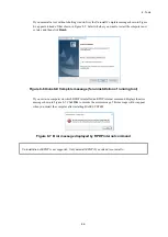
Page 137: ...s components appears Click Yes to uninstall the tool To cancel uninstallation of the tool click No Figure 8 4 Are you sure you want to uninstall the selected application and all of its components message 3 When uninstallation is complete the message Uninstall Complete appears Click Finish If a Remove Shared File window appears during uninstallation click No This leaves the shared file in place If ...

Page 138: ...nstall Complete message for uninstallation of running tool If you restart a computer on which RPDP is installed an RPDP internal command displays the error message shown in Figure 8 7 Click OK to dismiss the error message This message will not appear when you restart the computer after installing BASE SYSTEM Figure 8 7 Error message displayed by RPDP internal command Uninstallation of RPDP is not ...

Page 139: ...al tools To reinstall a tool you must first uninstall it You can then install it again For details on how to uninstall a tool see 8 2 3 3 Uninstalling individual tools For details on how to install a tool see 8 2 3 2 Installing individual tools ...

Page 140: ... install or uninstall a tool you must log on as an account with administrator privileges 1 To install or uninstall a tool from the basic installation set double click the SETUP exe file on the CD BASE SET S10VE 2 When you double click SETUP exe the following message might appear Click Yes to acknowledge the message and begin the setup process Figure 8 8 User Account Control message basic installat...

Page 141: ... click the Uninstall button uninstallation of the tool selected in the list begins Carry out the installation process by referring to step 2 onward in 8 2 3 3 Uninstalling individual tools and to the documentation for the tool you are uninstalling You will be returned to the Setup window when the uninstallation process has completed Repeat this step until all tools have been uninstalled 7 To reins...

Page 142: ... BASE SYSTEM normally or log on as a user who belongs to the RPDPusers group and use temporary administrator privileges to start BASE SYSTEM To open a project that uses C mode you need to start BASE SYSTEM normally on a system with RPDP installed as the administrator or a user belonging to the RPDPusers group 1 Starting BASE SYSTEM normally To start BASE SYSTEM in Windows 7 from the Start menu sel...

Page 143: ... Yes BASE SYSTEM starts Figure 8 10 3 Using BASE SYSTEM you started First create a new project or open an existing project When you open a project the features of BASE SYSTEM become available for use For details about projects see 8 4 2 Project functions To connect to PCs and use the functions of BASE SYSTEM you must set a communication type For details on how to set a communication type see 8 4 3...

Page 144: ...r details on how to start LADDER DIAGRAM SYSTEM from BASE SYSTEM see 8 4 4 1 Program menu LADDER Figure 8 11 Screen displayed when LADDER DIAGRAM SYSTEM starts For details on how to use LADDER DIAGRAM SYSTEM see the S10VE Software Manual Operation Ladder Diagram System for Windows manual number SEE 3 131 ...

Page 145: ... SYSTEM For details on how to start HI FLOW SYSTEM from BASE SYSTEM see 8 4 4 2 Program menu HI FLOW Figure 8 12 Screen displayed when HI FLOW SYSTEM starts For details on how to use HI FLOW SYSTEM see the S10VE Software Manual Operation HI FLOW for Windows manual number SEE 3 132 ...

Page 146: ...unctions From the BASE SYSTEM main menu select Program and then Setting Tool The Setting Tool window appears Select the name of the system whose setup tool you want to start and then click Execute The main window for the selected setup tool appears Use the setup tool to set up each module while referring to the documentation supplied with the option modules Figure 8 13 Setting Tool window ...

Page 147: ...ting BASE SYSTEM From the BASE SYSTEM main menu select Project and then End 8 3 2 2 Exiting the LADDER and HI FLOW systems From the LADDER DIAGRAM SYSTEM or HI FLOW SYSTEM main menu select File and then End 8 3 2 3 Exiting setup tools In the Setting main window of the setup tool click Close ...

Page 148: ... functions are available from the main menu Project A menu containing functions related to project files managed on the PADT side Online A menu that is available when there is a connection between the PADT and PCs Program A menu containing functions that start program tools LADDER SYSTEM HI FLOW SYSTEM and setup tools Setting A menu containing various setup functions RAS A menu containing various ...

Page 149: ...the project that is currently open as a four digit decimal number Communication type The method used for communication with the PCs The communication type is always Ethernet Ethernet is also displayed for ET NET connections IP address The IP address of the PCs to which BASE SYSTEM is connected PCs No IP address Communication type ...

Page 150: ...tegory Description Level 1 Level 2 Level 3 1 Project New Creates a new project 2 Open Opens an existing project 3 Close Closes the currently open project 4 Delete Deletes an existing project 5 Set Network Ethernet Sets the IP address and routing information for the CPU module 6 ET NET Sets the IP address and routing information for ET NET 7 Download CPMS Replaces the CPMS of the connected PCs 8 En...

Page 151: ... log on using multiple user accounts and switch between them without logging off You must log off before you can switch to another user account 1 From the main menu select Project and then New 2 The Properties window appears Figure 8 17 Properties window If a Properties window is already open the new window will appear when you close the existing one If you have not saved the settings in the open ...

Page 152: ... a new project If there is no existing project with the PCs number you specified a new project is created If C mode is enabled for the project BASE SYSTEM creates an RPDP site If RPDP is not installed the error message shown in Figure 8 19 appears Figure 8 19 Error message when RPDP is not installed In the following circumstances an error message is output indicating that the user does not have pe...

Page 153: ...ode usage enabled the RPDP site remains unchanged c Saving a project under a different PCs number new project If you specify a new PCs number for an open project the system makes a copy of the open project and assigns the copy the PCs number you specified CPMS The project is created using the CPMS of the open project This means that the CPMS of the copy might differ from the CPMS that is currently...

Page 154: ...lled C mode usage If C mode usage is enabled for the project that is assigned the specified PCs the system deletes the RPDP site However if any of the following apply the error message dialog box shown in Figure 8 24 appears and the RPDP site is not deleted The logged in user does not apply to the administrator does not belong to the RPDPusers group The logged in user does not apply to the adminis...

Page 155: ...he RPDPusers group The logged in user does not apply to the administrator started BASE SYSTEM from a standard account Multiple user accounts are logged in and the user has switched between them without logging off Figure 8 25 Error message indicating lack of site update permission If RPDP is not installed an error message to that effect appears Figure 8 19 6 Click Close to exit the project If you ...

Page 156: ...ho belongs to the RPDPusers group in an environment with RPDP installed 1 From the main menu select Project and then Open 2 The Project List window appears Figure 8 26 Project List window opening a project 3 The following parameters appear in the list PCsNo The PCs number of the project Mode C is displayed if C mode usage is enabled for the project Comment The comment associated with the PCs ...

Page 157: ... indicating that RPDP is not installed appears In either of the following circumstances an error message is output indicating that the user does not have permission to use the site The logged in user does not apply to the administrator does not belong to the RPDPusers group Multiple user accounts are logged in and the user has switched between them without logging off Figure 8 27 Error message ind...

Page 158: ...sers group and use temporary administrator privileges to start BASE SYSTEM Notice You cannot log on using multiple user accounts and switch between them without logging off You must log off before you can switch to another user account 1 From the main menu select Project and then Delete 2 The Project List window appears For details on the information displayed in the Project List window see 8 4 2 ...

Page 159: ...ciated RPDP site If RPDP is not installed an error message indicating that RPDP is not installed appears Figure 8 19 In any of the following circumstances an error message is output indicating that the user does not have permission to delete the site Figure 8 24 The logged in user does not apply to the administrator does not belong to the RPDPusers group The logged in user does not apply to the ad...

Page 160: ... CPU module s built in port Ethernet 1 and 192 192 193 1 as the IP address of its built in port Ethernet 2 It does not use the settings you make in this window The network configuration is available by clicking the Ethernet or ET NET menu item Menu item Network type Description Ethernet Ethernet 1 ET1 of CPU built in Ethernet port Ethernet 2 ET2 of CPU built in Ethernet port ET NET ET NET main ET ...

Page 161: ...reconfigure Ethernet 1 or Ethernet 2 if the need arises to connect the PADT via the CPU built in Ethernet If the same port is used for control and for connecting the PADT the performance on the control side is affected For this reason we recommend that you provide a dedicated port for PADT connection 1 From the main menu select Project Set Network and then Ethernet 2 The Set Network window appears...

Page 162: ...n numbers of Ethernet 1 and Ethernet 2 set the same setting as the ET ST No switch of the CPU module If you enter a different station number and click Set a message appears asking you to confirm the overwriting of the station number of the other Ethernet station Figure 8 31 Message asking for confirmation of Ethernet station number overwrite Note If you overwrite the station number for Ethernet 2 ...

Page 163: ... PCs is deleted 5 To replace the network information on the PCs with the information you set click the Write PCs button After writing the information to the PCs the system displays a message asking you to confirm that you want to reset the PCs Figure 8 32 Reset confirmation message Click the OK button to reset the PCs If you click Cancel the PCs are not reset If BASE SYSTEM successfully resets the...

Page 164: ...not successful Figure 8 34 Reset failed message In this case you will need to reset the PCs manually There are two ways to manually reset the PCs Turn the CPU RUN STOP switch from RUN to STOP and then back to RUN Turn the PCs off and then on again 6 Click Close to close the Set Network window ...

Page 165: ...ts network information for the ET NET main module ET NET Sub Sets network information for the ET NET sub module Note You can configure a maximum of two ET NET modules one designated the main module and the other the sub module IP Address Sub Net Mask and Broadcast Address Set the IP address subnet mask and broadcast address of the network selected in Select Network Setting Routes Num Network Addre...

Page 166: ...return to the Set Network ET NET window If you click Cancel the settings you entered are discarded and you are returned to the Set Network ET NET window 4 To replace the network information on the PCs with the network information you set click the Write PCs button in the Set Network ET NET window The Option module parameter setup list window appears Figure 8 37 Option module parameter setup list w...

Page 167: ...to the PCs If you do not want to overwrite the existing settings click Cancel You will be returned to the Option module parameter setup list window Figure 8 37 without any settings being written to the PCs You cannot apply the same network settings to more than one option module If the same settings are already applied to an option module a message appears that notifies you of this fact and asks y...

Page 168: ...BASE SYSTEM successfully resets the PCs it displays a message to that effect Figure 8 41 Figure 8 41 Reset successful message If the reset fails the system displays a message reporting that the reset was not successful Figure 8 42 Figure 8 42 Reset failed message In this case you will need to reset the PCs manually There are two ways to manually reset the PCs Turn the CPU RUN STOP switch from RUN ...

Page 169: ... module main or sub whose network you want to configure from the Select Network drop down list and then click the File open button An Open window Set Network ET NET appears Figure 8 43 Open window Set Network ET NET Select the file that contains the network information you want to use and then click Open Files that contain network information will have the extension pdat When you click Open the Fi...

Page 170: ...You are returned to the Set Network ET NET window which now displays the network information read from the file If the information in the selected file does not relate to the selected ET NET network a message appears indicating that the wrong file was selected Click OK to dismiss the message You will be returned to the Set Network ET NET window Figure 8 45 Wrong file selected message ...

Page 171: ...ule parameter setup list window deletion Select the module whose parameters you want to delete and then click Delete If option module parameters are set for the selected module a message appears asking you to confirm that you want to delete the parameters Figure 8 47 Confirm deletion message To delete the option module parameters click Yes If you do not want to delete the parameters click No You w...

Page 172: ... in the Set Network ET NET window A Save As dialog box appears Figure 8 48 Save As dialog box In the Save As dialog box specify the name of the file to which you want to save the network information If you click Save the File save window appears If you click Cancel the Save As dialog box closes ...

Page 173: ...cters You can also change the PCs number in this window Click File save to save the file with the specified file name The file will now be available to select when you click the File open button or can be used by functions that send and receive data If you click Cancel you are returned to the Set Network ET NET window without saving the file ...

Page 174: ... XXX Route2 XXX XXX XXX XXX XXX XXX XXX XXX Route3 XXX XXX XXX XXX XXX XXX XXX XXX Route4 XXX XXX XXX XXX XXX XXX XXX XXX Route27 XXX XXX XXX XXX XXX XXX XXX XXX Route28 XXX XXX XXX XXX XXX XXX XXX XXX Route29 XXX XXX XXX XXX XXX XXX XXX XXX Route30 XXX XXX XXX XXX XXX XXX XXX XXX Route31 XXX XXX XXX XXX XXX XXX XXX XXX Route32 XXX XXX XXX XXX XXX XXX XXX XXX CH2 IP Address XXX XXX XXX XXX Subnet ...

Page 175: ...umber PCs number Output as a decimal number 4 Module type For the main ET NET module ET NET Main For the ET NET sub module ET NET Sub 5 Network information for CH1 and CH2 The parameter settings for channels 1 and 2 6 Name of settings file pdat This item is not output if the setting parameters were not read from a file 10 Click Close to close the Set Network ET NET window ...

Page 176: ... then Download CPMS You will be unable to use this feature if the communication type is ET NET In this case the following message appears Figure 8 50 Error message when connected to ET NET module 2 The Download CPMS window appears Figure 8 51 Download CPMS window 3 Click Download to download the CPMS You cannot use this function if the RUN STOP switch of the CPU module is set to STOP In this case ...

Page 177: ...n the Change PCs window and then try downloading the CPMS again 5 The following window appears during the CPMS download which displays the progress of the download Figure 8 53 Progress window download If the ROM load operation fails during CPMS download the system displays a message asking you to confirm re execution of the ROM load operation Figure 8 54 Figure 8 54 Confirmation of ROM load re exe...

Page 178: ... details about the ROM load operation see SDRAM state during ROM load operation in 8 5 5 Scope of backup restoration and comparison 6 When the CPMS download has completed a Close button appears in the progress window The system assigns the PCs number of the open project to the PCs Information about the S10VE system is loaded into BASE SYSTEM and displayed in the status bar 7 Click Close to close t...

Page 179: ...t confirmation message end Click OK to reset the PCs If you click Cancel the PCs are not reset If the reset is successful the system displays a message to that effect Figure 8 33 If the reset fails the system displays a message reporting that the reset was not successful Figure 8 34 3 The system outputs an operation log For details about the contents of the operation log file see 8 6 1 Operation h...

Page 180: ...Cs Sets the communication type used for communication with the PCs 2 Display PCs STATUS and Change PCs STATUS Displays or changes the status of the PCs 3 Data send receive Sends receives and compares the setting information for option modules 4 Backup Receives CPU data from the PCs 5 Restore Sends backup data to PCs for restoration 6 Backup save data comparison Compares backup data with data on th...

Page 181: ...pe you entered to the project 5 To check whether communication is possible with the communication type you set place the CPU module in RUN mode and then click Test If BASE SYSTEM was able to successfully communicate with the CPU module it displays a message acknowledging a successful PCs connection Figure 8 60 Figure 8 60 Message when PCs connection is successful The Test button is unavailable imm...

Page 182: ...TATUS Displays the operating status of ladder logic on the PCs Status Description RUN Ladder logic is running STOP Ladder logic is stopped You can change the RUN STOP status of the PCs if the LADDER RUN STOP switch of the CPU module is set to RUN and STOP RUN contact input is OFF on the terminal block If the LADDER RUN STOP switch of the CPU module is set to STOP or STOP RUN contact input is ON on...

Page 183: ...otection error to the error log No Address range Description 1 0x0000 0000 to 0x001F FFFF Outside the PI O area 2 0x0047 2000 to 0x0047 FFFF RI O trace area and system area 3 0x004B 0000 to 0x004B 1FFF S10V compatible option module setting area 4 0x004C B000 to 0x004E FFFF Error log area 5 0x004F 2000 to 0x004F 9FFF System area 6 0x0110 0000 or above Outside the user area The following table lists...

Page 184: ...BIN APB 15 AUB 16 Decode DCD 17 Encode ECD 18 Square root SQR 19 Sine SIN 20 Cosine COS 21 Tangent TAN 22 Arcsine ASIN 23 Arccosine ACOS 24 Arctangent ATAN 25 Exponent EXP 26 Natural logarithm LOG 27 Clear XCLR 28 YCLR 29 GCLR 30 RCLR 31 KCLR 32 TCLR 33 UCLR 34 CCLR 35 VCLR 36 ECLR 37 FCLR ...

Page 185: ...ctions operate on the SH processor when index specification is specified as an argument To prevent malfunction stemming from user programming errors we recommend that you keep protection mode enabled ON unless you have a reason not to LADDER MODE Specifies whether to run ladder programs in normal mode or in simulation mode Status Description NORM Ladder programs run normally SIMU Ladder programs r...

Page 186: ...module For details about the LED states see 5 3 CPU module and 11 4 2 State transitions Status Description ON The ERR LED of the CPU module is lit OFF The ERR LED of the CPU module is off You cannot change the status of this item using the Change Status button STBY LED Shows the state of the STBY LED of the CPU module For details about the LED states see 5 3 CPU module and 11 4 2 State transitions...

Page 187: ...e ALARM LED of the CPU module is off You cannot change the status of this item using the Change Status button 4 Click Close to close the PCs Status window 8 4 3 3 Online menu Data send receive Use this item to send receive and compare option module settings 1 From the main menu select Online and then Data send receive 2 The Data Send Receive Option Module window appears Figure 8 62 Data Send Recei...

Page 188: ...ose module name is blank or which is assigned the same module type and module number as the option module settings you are sending 2 An Open window appears Select the file that you want to send Figure 8 63 Open window Data Send Receive When you click Open the Open window closes and the Send Data window appears To close the Open window click Cancel 3 Check the file information in the Send Data wind...

Page 189: ...ssage However if the PCs number in the file is 9999 the data will be sent regardless of the PCs number of the destination area Figure 8 65 Error message displayed when PCs numbers do not match Module identification code If the module type in the file differs than that of the destination area the system displays the following error message Figure 8 66 Error message displayed when module identificat...

Page 190: ...Cancel button will be unavailable after this time 5 When data transmission has completed the Cancel button in the progress window changes to a Close button 6 When data transmission has completed the system displays a message notifying you that the PCs will be reset and asking for your confirmation Figure 8 32 Click OK to reset the PCs If you click Cancel the PCs are not reset If BASE SYSTEM succes...

Page 191: ...ive 2 A Save As window appears Specify the name of the file where you want to save the data Figure 8 69 Save As window Data Send Receive When you click Save the Save As window closes and the Receive Data window appears To close the Save As window click Cancel 3 Make the necessary changes in the Receive Data window such as changing the PCs number or entering a comment Figure 8 70 Receive Data windo...

Page 192: ...haracters that helps identify the file This field is blank by default When you click Receive the Receive Data window closes and the system begins data reception If you click Cancel data reception is canceled and the Receive Data window closes 4 The following window appears displaying the progress of data reception Figure 8 71 Progress window receiving data If you click Cancel data reception is int...

Page 193: ...w closes and the Compare Data window appears To close the Open window click Cancel 3 Check the file information in the Compare Data window Figure 8 72 Compare Data window When you click Compare the Compare Data window closes and data comparison begins If you click Cancel data comparison is canceled and the Compare Data window closes 4 The following window appears displaying the progress of data co...

Page 194: ...rison error data file COMPARE_ERROR txt Figure 8 78 If the data is inconsistent and a comparison error data file already exists you will be asked if you want to overwrite the existing file Figure 8 75 If you click Yes the system overwrites the existing comparison error data file If you click No the system displays a first format of the message indicating that the data is inconsistent Figure 8 76 a...

Page 195: ...rds of data the system had read when it detected the inconsistent data Memory data The four longwords of data that were read starting from the memory address on the PCs File data The four longwords of data in the comparison data file starting from an offset corresponding to the memory address 6 Click Close to close the Data Send Receive window H0010 0000 M 1234ABCD 0001000 00000034 00000000 F 1234...

Page 196: ...dule not from the option module itself The option module concerned will continue to operate until removed 1 Select the area number whose settings you want to delete and then click Delete 2 A message appears asking you to confirm that you want to delete the data Figure 8 79 Click OK to delete the data If you click Cancel the data is not deleted Figure 8 79 Data deletion confirmation message ...

Page 197: ...sing the remote reset function This function can reset PCs even if it is running a ladder program 1 From the main menu select Online and then Remote Reset 2 A message appears asking you to confirm that you want to reset the PCs Figure 8 80 Remote reset confirmation message To reset the PCs click OK If you do not want to reset the PCs click Cancel 3 If BASE SYSTEM successfully resets the PCs it dis...

Page 198: ...rror message appears indicating that the function cannot be used when BASE SYSTEM is connected to an ET NET module Figure 8 50 2 A message appears asking you to confirm that you want to restart the PCs To restart the CPU module click OK Figure 8 81 Remote restart confirmation message 3 The system restarts the CPU module If the restart is successful the system displays a message to that effect Clic...

Page 199: ...H00482000 to H004837FF Work register FW000 to FWBFF 5 H00483800 to H00483FFF Long word register BD000 to BD1FE 6 H00490000 to H00497FFF Long word register LML0000 to LML1FFF 7 H00498000 to H0049FFFF Floating point register LG0000 to LG1FFF 8 H004A0000 to H004A7FFF Word register LXW0000 to LXW3FFF 9 H004F0000 to H004F1FFF Data register DW000 to DWFFF 1 From the main menu select Online and then Data...

Page 200: ...igure 8 85 Check the communication line between the PADT and PCs and then initiate the data clear operation again Figure 8 85 Error detected message 4 If BASE SYSTEM successfully resets the backup memory it displays a message to that effect Figure 8 33 If the reset fails the system displays a message reporting that the reset was not successful Figure 8 34 ...

Page 201: ...nu The following table lists and describes the program functions Table 8 5 List of Program menu items No Category Description Level 1 Level 2 Level 3 1 Program LADDER Starts LADDER DIAGRAM SYSTEM 2 HI FLOW Starts HI FLOW SYSTEM 3 Setting Tool Displays a list of tools You can display the setup window for a tool by selecting it from the list ...

Page 202: ...to start HI FLOW SYSTEM 1 From the main menu select Program and then HI FLOW 2 HI FLOW SYSTEM starts 8 4 4 3 Program menu Setting Tool Use this menu item to display a list of tools installed on the PADT You can display the setup window for a tool by selecting it from the list of option module tools 1 From the main menu select Program and then Setting Tool 2 The Setting Tool window appears Figure 8...

Page 203: ...d then click Execute The main setup window for the configuration tool appears If the system is unable to start the tool the following error message appears Figure 8 88 Error message displayed when selected tool cannot be run 5 To save the contents of the list to a text file click the Save List button A Save As window appears When you click Save in the Save As window the system saves the contents o...

Page 204: ...the Setting menu Figure 8 89 Window after clicking the Setting menu The following table lists and describes the setting functions Table 8 7 List of Setting menu items No Category Description Level 1 Level 2 Level 3 1 Setting Set Time Shows or sets the clock of the CPU module ...

Page 205: ...efault the system retrieves and displays the time from the CPU module Figure 8 90 Set Time window 3 If you want to change the time displayed in the Set Time window enter the new time in the fields provided You can input the time setting of the PADT by clicking the Get Time of PC button 4 To update the CPU module with the new time setting click Write PCs 5 Click Close to close the Set Time window ...

Page 206: ... Man machine Communication System is a collective term for the functions that support writing to and reading from PCs memory 5 Display Performance Displays the sequence cycles and the CP HP load ratio 6 Event Register Displays the ON OFF state of the event register 7 Network Information Displays network information 8 Ethernet Communication of Trace Log LADDER Displays the Ethernet communication lo...

Page 207: ... the items displayed in the Module List window Table 8 9 Items in Module List window No Area No Item Description 1 Module List 1 Name The name of the CPMS firmware or installed module 2 Model The model number of the installed module 3 Ver Rev The version and revision number of the microprogram installed on the module in the format version number revision number 2 P P List 1 Name The name of the to...

Page 208: ...log information for the ET NET module or for the CP side of the CPU module from the main menu select RAS Error Log Display and then CP Error Log Display To display error log information for the HP side from the main menu select RAS Error Log Display and then HP Error Log Display 2 The Display Error log CP or Display Error log HP window appears Figure 8 93 Display Error log CP window Figure 8 94 Di...

Page 209: ...ror log information for the ET NET main module 3 ET NET SUB Error log information for the ET NET sub module 4 The following table explains the items that appear in the Display Error log CP window and the Display Error log HP window Table 8 11 Items displayed in Display Error log CP and HP windows No Item Description 1 Error code The error code 2 Contents The information the error code represents 3...

Page 210: ...panic logs First pattern UNO DEV TN SLOT 1 2 3 4 5 1 Error severity type F Fatal error W Warning E Error I Information 2 Error message 3 Unit number device number Range of unit numbers 1 to 24 Range of device numbers 0x00000000 to 0xFFFFFFFF 4 Task number Range of task numbers 1 to 300 5 Slot number Range of slot numbers 0 to 7 Note In the first pattern for non panic logs the information in 3 to 5...

Page 211: ...og as a four digit hexadecimal number 5 To display detailed error information click Error Log Detail to display the Error Log Detail window 6 To display the latest error information click Refresh 7 To sort error information in ascending or descending order of when the error occurred click Sorting Each time you click Sorting the list switches between ascending and descending order of occurrence tim...

Page 212: ...explanation of the information displayed as detail data see 8 4 6 2 RAS menu Error Log Display For further information about DHP data see 8 4 6 9 RAS menu DHP Information CPMS E HARD 0004 SITE 0301cp RC 00000000 2018 01 15 14 30 41 LOG 116 EC 50032060 I O error J NET Slave response Timeout error Error code System that detected error Error severity Fault location Message describing nature of error ...

Page 213: ...by WDT WatchDog Timer monitoring I O error An error related to input output operations Module error Primarily hardware errors For details about other error types see the documentation for each module Error severity F Fatal Error E Error W Warning I Information Fault location HARD Hardware CPMS CPMS SOFT Software other than CPMS Code A code that represents the error log type 4 Click Next Error Log ...

Page 214: ...names in the register are displayed as both S10mini compatible addresses and S10VE extended addresses regardless of whether the Compatible PI O check box is selected Example The address of the J000 register is displayed as 0x202000 when the check box is cleared and 0xA2000 when the check box is selected 4 Click Read to read the contents of the displayed addresses from the PCs 5 Click Write to writ...

Page 215: ...nput a decimal value when changing a value in memory HEX The memory contents are displayed as hexadecimal values You must input a hexadecimal value when changing a value in memory 10 In the WO LO FL group box select the data type to use when displaying memory contents The default is WORD WORD Data is displayed as 2 byte integers LONG Data is displayed as 4 byte integers FLOAT Data is displayed as ...

Page 216: ... changes to Stop Monitoring During monitoring the Performance window displays the CP and HP load ratios as a graph 5 To stop performance monitoring click Stop Monitoring Performance monitoring stops and the button changes to Start Monitoring 6 To save the information gathered by the performance monitoring function to a file in CSV format click CSV Output 7 Click Close to close the Performance wind...

Page 217: ...CP HP XXXXXXXXXX YYYYYYYYYY XXXXXXXXXX YYYYYYYYYY XXXXXXXXXX YYYYYYYYYY XXXXXXXXXX YYYYYYYYYY XXXXXXXXXX CP side load factor expressed as floating point numeral from 0 to 100 YYYYYYYYYY HP side load factor expressed as floating point numeral from 0 to 100 ...

Page 218: ... Event register monitoring starts and the button changes to Stop Monitoring During monitoring the on screen elements in the Event Register Monitor window change colors to reflect the state of the corresponding bit When the bit is OFF The corresponding element is displayed in white When the bit is ON The corresponding element is displayed in red 4 To stop monitoring the event registers click Stop M...

Page 219: ...lect the network whose network information you want to display from the Selection of the network drop down list Table 8 12 Items in Selection of the network drop down list No Network name Remarks 1 CPU ET1 2 CPU ET2 3 ET NET MAIN CH1 Does not appear if no ET NET main module is installed 4 ET NET MAIN CH2 Does not appear if no ET NET main module is installed 5 ET NET SUB CH1 Does not appear if no E...

Page 220: ...ed to the IP protocol 6 Displays statistical information related to the ICMP protocol 7 Displays statistical information related to the TCP protocol 8 Displays statistical information related to the UDP protocol 9 Statistics Displays statistical information about the interfaces 10 ARP Displays ARP table information 5 Click Refresh to display network information in the category you selected 6 To sa...

Page 221: ...nction This window displays trace log information for errors that occur in relation to ladder Ethernet communication The contents of this trace information is as follows Table 8 14 Information in Ethernet communication trace log LADDER No Item Displayed information 1 ID The management table number for ladder Ethernet communication 2 Module The module name 3 Trace The trace code of the trace inform...

Page 222: ...error was detected 6 Details of error code The detailed error code output when the error was detected 7 Contents The contents of the error code of the error 8 Time The time when the error occurred For details on traces see Appendix F List of DHP Codes in the S10VE Software Manual CPMS General Description and Macro Specifications manual number SEE 3 201 For details on error codes see the list of de...

Page 223: ...ation to a text file click Save Select a folder and specify a file name in the Save As window that appears and then click Save to save the trace log information to the file Figure 8 104 Save As window 6 Click Close to close the Display Ethernet Communication of Trace Log window ...

Page 224: ...tion you want to display or set 3 To display DHP information for the CP side select the CP side radio button and then click Select To display DHP information for the HP side select the HP side radio button and then click Select The CPU side and HP side radio buttons will be unavailable if you selected ET NET MAIN or ET NET SUB from the Module Name list 4 The value shown for Logging Mode is the cur...

Page 225: ...formation displayed in this window Item Displayed information DHP The DHP trace display number TIME The time at which the trace was recorded tt tttttt Second Time output to one microsecond EVENT The trace point type TN The task number LV The priority level DATA1 to DATA5 The trace data in hexadecimal format 5 To display the latest DHP trace information click Refresh 6 To save the displayed DHP tra...

Page 226: ...indow 3 To create an autosave file and a fault analysis information file click Get Data You will be unable to use this feature if the communication type is ET NET In this case an error message appears Figure 8 50 You will be unable to use this feature if the CPU is in RUN mode In this case the following error message appears Figure 8 108 Error message when CPU is in RUN mode If communication fails...

Page 227: ...Cs for which the AutoSave file is being saved If the system successfully creates the autosave file and fault analysis information file it displays a message indicating that processing has completed Figure 8 111 Figure 8 111 Processing completed message The autosave file and fault analysis information file are given the following names Autosave file XXXX atdmp Fault analysis information file CP sid...

Page 228: ... 0xA100 0000 0xA100 4000 0xA100 0xA100 0xA100 F000 0xA100 F800 0xA101 0000 0xA248 0000 0xA260 0000 MRAM address map Autosave file 0x0000 0000 Main memory 128 MB 0x0000 0200 0x0800 0200 0x0808 B200 Autosave file header 512 bytes MRAM 556 KB Main memory map SPM CPMS for HP CPMS for CP LADDER MAP HP TASK HP GLBR HP GLBW HP SUB HP OS table HP OS table CP Network buffer 0x0008 0x001f 0000 0x0036 0x0000...

Page 229: ... FATAL error log information 3 OSCB information 4 SYSCB information 5 HAICB information 6 Memory patrol information 7 Title 2 8 DHP information 9 Title 3 10 NONFATAL error log information 11 Title 4 12 TCB information 13 Title 5 14 UCB information 15 Title 6 16 TMCB information 17 Title 7 18 RSCB and RSVB information 19 Title 8 20 VER information 21 Title 9 22 Bus error count information Figure 8 ...

Page 230: ...elper trace list AAA BBB CC DD EE FF HHHH SITE XXXX 9 Title 3 Non fatal error log List AAA BBB CC DD EE FF HHHH SITE XXXX 11 Title 4 Task Control Block list AAA BBB CC DD EE FF HHHH SITE XXXX 13 Title 5 Unit Control Block list AAA BBB CC DD EE FF HHHH SITE XXXX 15 Title 6 Timer Control Block list AAA BBB CC DD EE FF HHHH SITE XXXX 17 Title 7 Reserve Control Block list AAA BBB CC DD EE FF HHHH SITE...

Page 231: ... The time second when the fault analysis information file was created HHHH The year in which the fault analysis information file was created XXXX The site name assigned to the PCs 2 FATAL error log information FATAL error log information is output if it exists A maximum of two items are output If there is no FATAL error log information the message No error log appears here 10 NONFATAL error log in...

Page 232: ... a number of seconds since 1970 idlesec The idle time since the CPMS started in seconds idlensec The idle time since the CPMS started in nanoseconds ulsubctl The address of the ulsubctl table tcba The address of the tcb table syscba The address of the syscb table ucba The address of the ucb table trba The address of the trb table rscba The address of the rscb table rsvba The address of the rsvb ta...

Page 233: ...can be exclusively used at any one time log_buf_top The address of the log area log_buf_size The size of the log area dhp_buf_top The address of the trace area dhp_buf_size The size of the trace area mbuf The mbuf address portflg LANCE and serial port control multi_sys Information about the CPU configuration sysno The CPU type maxpu The number of processors stopall CPU stop request cyclctl The add...

Page 234: ...t xxxxxxxx ecc3cordat_ul xxxxxxxx ecc3corsum xxxxxxxx tv_sec 3 xxxxx ecc3status xxxxxxxx ecc3coradr xxxxxxxx ecc3cordat xxxxxxxx ecc3cordat_ul xxxxxxxx ecc3corsum xxxxxxxx tv_sec 4 xxxxx ecc3status xxxxxxxx ecc3coradr xxxxxxxx ecc3cordat xxxxxxxx ecc3cordat_ul xxxxxxxx ecc3corsum xxxxxxxx mempat_addr The refresh start address mempat_cnt Error counter mempat_log Warning output flag mempat_idx The p...

Page 235: ... suppressed Idle Waiting to start Ready Running or waiting to execute Suspended Execution is suspended Wait Waiting for an event to occur The task is registered but its status is none of the above flag The task status as one of the following QBF Multiple start flag DELAY Execution is suppressed by DELAY flag SUSP Execution is suppressed by SUSP flag SRV Waiting for a resource RSERV or PRSRV to be ...

Page 236: ...B table 16 TMCB information TMCB uatrp xxxxxxxx urtrp xxxxxxxx ftrp xxxxxxxx uatrp FP INTM CYTM TN FACT ID xxxxxxxx xxxxxxxx xxxxxxxx xxxxxxxx xxxxxxxx xxx xxxx x urtrp FP INTM CYTM TN FACT ID xxxxxxxx xxxxxxxx xxxxxxxx xxxxxxxx xxxxxxxx xxx xxxx x Maximum of 512 sets of information uatrp The start TRB address of the absolute time TRB queue urtrp The start TRB address of the relative time TRB queu...

Page 237: ... task number of the task that has exclusive use of the shared resource TOP The start address of the shared resource GLB LAST The end address of the shared resource GLB 20 VER information No PPName PPversion SInumber loadpkg Time 1 CPMS S10VE XX XX XX XX XX XX XX XX XX 2 RCTLNET S10VE XX XX XX XX XX XX XX XX XX 3 RPDP S10VE XX XX XX XX XX XX XX XX XX Maximum of 64 sets of information No The number ...

Page 238: ...eout error was detected The fault analysis file on the CP side also contains bus error count information for slots 0 to 7 The output format is as follows SLOTX maae xxxxxxxx piome xxxxxxxx ackbusyto xxxxxxxx rserr xxxxxxxx invcmd xxxxxxxx sta xxxxxxxx tape xxxxxxxx tdpe xxxxxxxx me xxxxxxxx nodtack S10 BUS xxxxxxxx nodtack xxxxxxxx tserr xxxxxxxx Seven sets of information SLOT The master slot numb...

Page 239: ... The following table lists and describes the CPMS debugger functions Table 8 16 List of CPMS Debugger menu items No Category Description Level 1 Level 2 Level 3 1 CPMS Debugger Task Abort Places a task in a condition that not allow its execution 2 Display Task Status Displays the status of registered tasks in a list 3 Initialize Task Initializes the task environment ...

Page 240: ...rmation window appears asking you to confirm that you want to abort the task Figure 8 116 Task abort confirmation message Click Yes to suppress startup of the specified task If the system successfully suppresses startup of the task it displays a message indicating that the process is complete If suppression fails the system displays an error message For details on the error messages displayed in t...

Page 241: ... 3 Click Refresh to display a list of registered tasks and their status in the Task Registration area The following table describes the information displayed in the Task Registration area of the Task Status window Table 8 17 Information in Task Registration area No Heading Description Remarks 1 tn Task number 2 task status Task status See Table 8 18 3 level Execution level Initial execution level ...

Page 242: ...tatuses No Shown as Description 1 DORMANT Start is suppressed 2 IDLE Waiting to start 3 READY Running or waiting to execute 4 WAIT Waiting for an event 5 SUSPENDED Execution is suppressed 4 Click Close to close the Task Status window ...

Page 243: ...unication type is ET NET an error message indicating that the function cannot be used with ET NET is displayed Figure 8 50 when you click Execute 2 The Initialize Task window appears Figure 8 118 Initialize Task window 3 To initialize the task environment click Execute If CPMS has not been downloaded the system displays an error message to that effect Figure 8 119 Figure 8 119 Error message when C...

Page 244: ...sing revised ST numbers 5 The following window appears displaying the progress of task environment initialization Figure 8 121 Progress window initializing task environment If the ROM load operation fails during task environment initialization the system displays a message asking you to confirm re execution of the ROM load operation Figure 8 54 If this message appears turn the PCs off and on again...

Page 245: ... Scope of backup restoration and comparison When initialization has completed a Close button appears in the progress window The CPU enters STOP mode while the task environment is being initialized When initialization is complete the CPU returns to RUN mode 7 Click Close to close the Initialize Task window ...

Page 246: ... ET NET an error message indicating that the function cannot be used with ET NET is displayed Figure 8 50 If the CPU mode of the PCs is RUN a message appears asking you to confirm that the CPU mode can be changed to STOP Figure 8 122 CPU stop confirmation message for backup function Click OK to place the CPU in STOP mode If you click Cancel a message appears indicating that the backup process will...

Page 247: ... The default is PCsNNNN where NNNN is a four digit PCs number 4 In the Position field specify the location at which to create the backup folder You can enter a maximum of 200 characters You can select a path by clicking the Refer button When you click Refer a Browse For Folder dialog box appears in which you can select a folder The total number of characters including the folder name and path cann...

Page 248: ...up folder you specify already exists a message appears asking you to confirm that you want to overwrite the existing data Click OK to overwrite the existing data with the received backup data If you click Cancel you are returned to the Backup window Figure 8 125 Overwrite confirmation message 8 After approximately 30 seconds reception of the backup data begins and the State of backup window appear...

Page 249: ...message appears asking you to confirm that you want to change the CPU mode to RUN Figure 8 128 Figure 8 128 CPU RUN confirmation message When you click OK in this message the State of backup window appears as follows Figure 8 129 State of backup window when backup is canceled If you respond Cancel to the CPU RUN confirmation message a message appears letting you know how to recover from STOP mode ...

Page 250: ... return to the Backup window Figure 8 123 9 If you selected the Comparison of save data check box the system compares the backup data it receives with the data on the PCs During this comparison the State of backup window appears as follows Figure 8 131 State of backup window when comparing data If you click Cancel a message appears asking you to confirm that you want to cancel data comparison Figu...

Page 251: ...essage appears letting you know how to recover from STOP mode Figure 8 130 Click OK to dismiss the message The State of backup window appears Click Close in this State of backup window to return to the Backup window If the State of backup window does not appear during the backup process it might be hidden behind the active window To check whether this is the case align your mouse pointer with the ...

Page 252: ...N mode If you click Cancel the CPU module remains in STOP mode and the system displays a message letting you know how to recover from STOP mode Click OK to dismiss the message Click Close in the State of backup window Figure 8 134 You are returned to the Backup window Go to step 11 Figure 8 134 State of backup window when no inconsistencies are found If the message indicates that inconsistencies w...

Page 253: ...cts an inconsistency in one of these units it outputs the memory address memory data and file data to the COMPARE_ERROR txt file Memory address The starting address of the four longwords of data the system had read when it detected the inconsistent data Memory data The four longwords of data that were read starting from the memory address on the PCs File data The four longwords of data in the comp...

Page 254: ...CPU STOP instruction issued OFF ON The user has clicked OK in the CPU STOP confirmation message Immediately after execution OFF BLINK The user has just clicked the Execute button The contents of the NAND flash memory are being copied to main memory Data reception has started OFF ON Data is being received from the PCs Data reception has finished OFF ON Data has been received from the PCs Data compa...

Page 255: ...t Online and then Restore You will be unable to use this feature if the communication type is ET NET In this case an error message appears Figure 8 50 If the CPU module of the PCs is in RUN mode a message appears asking you to confirm that you want to place the CPU in STOP mode Figure 8 137 If the CPU module of the PCs is in STOP mode an error message appears indicating that the function cannot be...

Page 256: ...ecomes available when you select a folder from which backup data can be restored 4 The PCs number field shows the PCs number of the PCs to which BASE SYSTEM is connected If the CPU module is new 0000 is displayed as the PCs number 5 If you want the system to compare the local data with the data on the PCs to confirm that it was sent correctly select the Comparison of load data check box 6 Click th...

Page 257: ...estoring a backup to a new CPU module Figure 8 139 Message asking whether to continue restoration 8 The system displays the following State of Restore window while the data to be restored is being transferred Figure 8 140 State of Restore window when sending data 9 If you selected the Comparison of load data check box when the system has sent the data to be restored it starts to compare the sent d...

Page 258: ...ow you can change the PCs number of the backup data you have restored Figure 8 143 Window for changing PCs number of restored PCs By changing the PCs number and then clicking OK you can change the PCs number of the restored PCs from the PCs number saved in the backup data If you click Cancel the PCs number in the backup data is assigned to the PCs to which the data was sent and the restoration pro...

Page 259: ...ce the CPU module in RUN mode If you click Cancel the CPU module remains in STOP mode and the system displays a message letting you know how to recover from STOP mode Figure 8 145 Click OK to dismiss the message Figure 8 144 CPU RUN confirmation message Figure 8 145 STOP recovery guidance message If the comparison finds inconsistencies in the data the CPU module enters STOP mode and the system dis...

Page 260: ...e COMPARE_ERROR txt Figure 8 136 in the specified folder Click Close You are returned to the Restore window Go to step 2 and perform the restoration process again Figure 8 147 State of Restore window when inconsistencies are found 14 Click Close in the Restore window The restoration process finishes and you are returned to the BASE SYSTEM window 15 If the comparison finds inconsistencies in the da...

Page 261: ... 1 OFF BLINK Data has been transmitted to the PCs the contents of the main memory are being copied to NAND flash memory Data transmission has finished 2 OFF ON Data transmission to the PCs has completed Data transmission has finished 3 OFF BLINK The system is preparing to compare the data the contents of NAND flash memory are being copied to main memory Data comparison has started OFF ON The data ...

Page 262: ...e and then Backup save data comparison You will be unable to use this feature if the communication type is ET NET In this case an error message appears Figure 8 50 If the CPU module of the PCs is in RUN mode a message appears asking you to confirm that you want to place the CPU in STOP mode Figure 8 149 Figure 8 149 CPU stop confirmation message for backup data comparison Click OK to place the CPU...

Page 263: ... the PCs number of the PCs to which BASE SYSTEM is connected 5 Select the backup data in the folder list and then click Execute to start comparing the backup data 6 If the specified backup file has a different PCs number from the PCs whose data you are comparing it with the system displays a message asking you to confirm that you want to continue with the comparison Figure 8 151 If you click OK th...

Page 264: ...State of Backup save data comparison window during data comparison 8 If you click Cancel in the State of Backup save data comparison window a message appears asking you to confirm that you want to cancel backup data comparison Figure 8 153 Figure 8 153 Confirmation message when canceling backup data comparison If you click No comparison of the backup data resumes If you click Yes data comparison i...

Page 265: ...e data comparison window appears as follows Figure 8 155 Figure 8 155 State of Backup save data comparison window when no inconsistencies are found 10 If comparison of the backup data reveals inconsistencies with the data on the PCs the State of Backup save data comparison window appears as follows Figure 8 156 Figure 8 156 State of Backup save data comparison window when outputting comparison err...

Page 266: ...ing comparison error data file Click Yes to overwrite the existing COMPARE_ERROR txt file in the specified backup folder If you click No the existing file is not overwritten 11 If the CPU mode of the CPU module was changed to STOP at the beginning of this procedure a CPU RUN confirmation message appears when the backup data comparison is finished or canceled Figure 8 144 12 If you respond OK to th...

Page 267: ...en received from the PCs Data comparison has started OFF ON The data on the PADT is being compared against the received data Data comparison has finished OFF ON The data on the PADT has been compared against the received data If the State of Backup save data comparison window does not appear during the backup data comparison process it might be hidden behind the active window To check whether this...

Page 268: ...n the performance of the PADT The times in the table were measured on a PADT with the following specifications Installed memory 2 GB CPU Core i5 2 53GHz OS Microsoft Windows 10 Professional Table 8 19 Measured backup restoration times Command Time taken Backup Without comparison 5 minutes 00 seconds With comparison 5 minutes 45 seconds Restoration Without comparison 9 minutes 10 seconds With compa...

Page 269: ...rea 512 KB and user area 1 MB 2 The first SDRAM address range is the physical address range in SDRAM The address range in parentheses is the corresponding address range in NAND flash memory The data copied from the NAND flash memory to SDRAM is stored in the file backup1 bur and the MRAM data is stored in the file backup3 bur SDRAM state during ROM load operation When creating or comparing backup ...

Page 270: ...ject to backup operation in the S10VE To back up or restore data in the NX user buffer area use the data transmit receive function of LADDER DIAGRAM SYSTEM S10VE to select Save new or Save or Send in online mode For details about how to use the data transmit receive function see 4 7 11 Send receive data in the S10VE Software Manual Operation Ladder Diagram System for Windows manual number SEE 3 13...

Page 271: ...000 006F 1 16 sectors 8 192 bytes RPDP usage area Residual data is excluded H0000 0400 to H0002 9EDF 1 170 720 sectors approx 83 MB OS management area ROM load operation extends to the final address of the ROM image 1 Corresponding address in NAND flash memory 2 PI O RAM backup area 512 KB user area 1 MB 3 Scope of comparison The system compares the same range of data as that in 1 Scope of backup ...

Page 272: ...tput in descending order of when it occurred That is the most recent information appears at the beginning of the file BASE SYSTEM saves operation history to a file named S10VElog txt which is stored in the same folder as the BASE SYSTEM executable files The format of the operation record file is as follows 2018 01 01 12 05 00 End 2018 01 01 12 04 00 Change PCs Close 2018 01 01 12 03 30 Change PCs ...

Page 273: ... Display PCs STATUS and Change PCs STATUS Display PCs STATUS and Change PCs STATUS 10 Data send receive Data send receive 11 Remote Restart Remote Restart 12 Remote Reset Remote Reset 13 Data Clear Data Clear 14 LADDER LADDER execute 15 HI FLOW HI FLOW execute 16 Setting Tool Setting Tool 17 Set Time Set Time 18 Module List Module List 19 Error Log Display Error Log Display 20 MCS MCS 21 Display P...

Page 274: ...s Status Get Status PCs Status Get 44 Change Status PCs Status Change Item xxx Status xxxx xxxx 45 Close PCs Status Close 46 Data Send Receive Send Data send receive Send NO xxxx name xxxx 47 Receive Data send receive Receive NO xxxx name xxxx 48 Compare Data send receive Compare 49 Delete Data send receive Delete 50 Close Data send receive Close 51 Set Time Write PCs Set Time Write PCs 52 Get Tim...

Page 275: ... Route Information Network ET NET Route Set 77 Write PCs Network ET NET Write PCs 78 Read PCs Network ET NET Read PCs 79 File save Network ET NET File save 80 File open Network ET NET File open 81 CSV Output Network ET NET CSV Output 82 Close Network ET NET Close 83 Display Ethernet Communication of Trace Log LADDER When opened Ethernet Communication Trace Log LADDER 84 Display Ethernet Communicat...

Page 276: ...e in the Project window Table 8 24 List of CPMS file contents No File name Contents 1 OSfile The CPMS itself and its system tasks system area and so on 2 OSinitfile Initial information such as OS tables TCB RSUBT and IRGLBT 3 LAinitfile1 Management table information for the ladder diagram system 4 LAinitfile2 Program information for the ladder diagram system ...

Page 277: ... in the Properties window with Use C mode selected Make sure that you are able to write to the folder that contains the S10VEBASE exe file 2 If the error occurs in another situation Check the state of the destination folder specified for the output file 3 Failed to create a file Check the state of the destination folder specified for the output file 4 File data is invalid Check the contents of the...

Page 278: ...tion paths 17 Failed in execution due to a communication error Check the communication paths 18 Failed to acquire the PCs number Check the communication paths 19 Failed to reset PCs Check the communication paths 20 Failed to read the IP information file for the BASE SYSTEM Check the state of the C S10VE setipa_S10VE def file 21 No IP address is set for the IP information file for the BASE SYSTEM S...

Page 279: ... the OS file Check whether the C windows renix usr rpdp_hce etc boot current OSfile folder exists If this folder does not exist you will need to install CPMS 9 Failed to copy the OS initial information file Check whether the C windows renix usr rpdp_hce etc boot current OSinitfile folder exists If this folder does not exist you will need to install CPMS 10 Failed to copy the LADDER initial informa...

Page 280: ...ot provided Perform the operation as the administrator or as a user who has administrator privileges and belongs to the RPDPusers group 21 Site deletion right is not provided Perform the operation as the administrator or as a user who has administrator privileges and belongs to the RPDPusers group 22 Failed to update the IP information file for BASE SYSTEM Check the state of the C S10VE setipa_S10...

Page 281: ...execute this operation Close all windows except the Properties window and the Project List window 2 No project is open Table 8 31 Set Network window No Error message Action to take 1 Failed to update the IP information file for the BASE SYSTEM Check the state of the C S10VE setipa_S10VE def file 2 Right to write the IP information file for the BASE SYSTEM is not provided Execute this operation as ...

Page 282: ... Check the communication paths Also check the error code in Table 8 48 If the error code is unknown contact the system administrator 11 Failed in the CPU reset start Module xr_rrw_grstart Error error code Check the communication paths Also check the error code in Table 8 48 If the error code is unknown contact the system administrator 12 Failed in the CPU reset start option module is STOP An optio...

Page 283: ...on to take 1 Failed to write data to the operation log Check the state of the folder that contains the S10VEBASE exe file 2 Operation log write right is not provided Check whether you are able to write to the folder that contains the S10VEBASE exe file ...

Page 284: ...dp_r etc setipa d ef file 5 Right to write the IP information file for the RPDP is not provided Execute this operation as an administrator Perform the operation as an administrator 6 Failed to update rpc_def e Check the state of the C S10VE xxxx xxxx_unit xxxxcp etc gen rpc_ def e file where xxxx is the PCs number 7 Failed to read data Check the communication path including cable connection Module...

Page 285: ...ation state 11 The ladder is in the normal state Table 8 36 Data Send Receive window No Error message Action to take 1 Failed to load the module list Check the communication paths 2 Select a module Select a module 3 PCs number in the data does not match the destination PCs number Check the specified file 4 Module identification code in the data does not match the module identification code of the ...

Page 286: ...e Specify a name in the Name field 8 The following character cannot be used Review the path specified in the Position field 9 Continuous of two or more characters cannot be used Review the path specified in the Position field 10 For the following files exist the compare can not be performed Evacuation the file please execute the compare again File file name Take remedial action as described in the...

Page 287: ...code is unknown contact the system administrator 22 Failed to read the file File name file name Check the state of the file shown in the message 23 Failed to reboot the CPU Module xr_rrw_grstart Error error code Check the communication paths Also check the error code in Table 8 48 If the error code is unknown contact the system administrator 24 Failed to save the ROM Error error code Check the err...

Page 288: ...d 4 Select a menu after installing P P of LADDER DIAGRAM SYSTEM Install the LADDER SYSTEM software product Table 8 40 Setting Tool window No Error message Action to take 1 No tool is selected Select a tool and then perform the operation again 2 Cannot run the same tool any more 3 Failed to run the tool Check the state of the selected tool 4 Cannot execute the selected tool 8 8 5 Setting menu Table...

Page 289: ...time Enter a measurement unit time 2 Invalid unit measurement time Enter a correct value 3 Specify the unit measurement time to be a multiple of sequence cycle up to 100 times Enter a value that is a multiple a maximum of 100x of the sequence cycle 4 No data Perform the operation again with data displayed in the graph Table 8 44 DHP Information window No Error message Action to take 1 Close the CP...

Page 290: ...9 Enter a number within the permitted range 3 The first number is not input When there is only one task number enter it as the first number Enter the number of the first task you want to abort 4 Enter the first task number in the left box and the last task number in the right box The first task number is larger than the last task number Enter the first task in the left field and the last task in t...

Page 291: ...ket If there is no issue with the communication paths contact the system administrator 7 Failed in the CPU STOP processing Module xr_rrw_stop Error error code Check the communication paths Also check the error code in Table 8 48 If the error code is unknown contact the system administrator 8 Failed in the CPU reset start Module xr_rrw_grstart Error error code Check the communication paths Also che...

Page 292: ...t was specified If there is no issue with the communication paths contact the system administrator 10 Line error Failed to generate a socket If there is no issue with the communication paths contact the system administrator 11 Line error Failed to allocate the memory If there is no issue with the communication paths contact the system administrator 12 Line error The network is disconnected If ther...

Page 293: ...e to allocate memory for frame creation H5 Unable to send data H6 Response timeout error H7 Maximum number of retries exceeded while waiting for response cable disconnected H8 Unable to receive data H18 Storage area address error 0 specified dmaia H19 Storage area address error 0 specified reta H8000000X Error reported in response status code in CPU control header X Status code 4 µΣNETWORK 1000 ne...

Page 294: ...esiteos Error Nature of error 1 Abnormal termination 2 Data cannot be updated because the addresses of the user area of the base site overlap with those of the destination 3 Data cannot be updated because the name of a user resource of the base site is the same as the name of a user resource at the destination Table 8 51 svsitedel Error Nature of error 1 The site could not be deleted 2 The project...

Page 295: ...This page is intentionally left blank ...

Page 296: ... L 0 to E To use the following fixed IP addresses U F L F ET1 IP address 192 192 192 1 ET2 IP address 192 192 193 1 Note If you will not be using Ethernet communication set U F and L F This is to allow the PADT to connect for maintenance purposes See 5 3 Connection of primary battery Connect the primary battery Open the cover on the left side of the CPU module and connect the cable for the primary...

Page 297: ...erent numbers of I O points set the highest number among the installed PI O modules See 9 3 4 Ladder synchronous asy nchronous mode setting Set whether to synchronize remote I O signals with ladder processing To synchronize remote I O signals with ladder processing Ladder synchronous mode To not synchronize remote I O signals with ladder processing Ladder asynchronous mode See 9 3 5 Remote I O opt...

Page 298: ...e a module installed in the PI O unit see the manual for that module S10mini Hardware Manual I O Modules manual number SME 1 114 S10mini Hardware Manual D Station manual number SME 1 119 HSC 2100 Hardware Manual I O Modules manual number SME 1 126 ...

Page 299: ...n number 00 Set the station numbers of PI O units connected to RI O 1 line 1 so as not to conflict with the station number of the CPU unit CPU PS RI O IF CPU unit Max 12 units per line RI O 1 line 1 When the PI O module is installed in the CPU unit the CPU unit is assigned a station number of 00 and an I O number from 0000 However the I O numbers that correspond to the first slot 0 are invalid PI ...

Page 300: ... 9 3 1 PI O installation setting Perform this setting when installing a PI O module in the CPU unit If you specify Used a station number and I O numbers are assigned to the CPU unit as follows The first station number 00 is assigned to the CPU unit However some I O numbers are invalid For details see 9 3 4 I O point number setting I O numbers are allocated automatically within a range determined b...

Page 301: ...purposes and another for output purposes X0AAA and Y0AAA This allows you to specify the I O number that is appropriate for the PI O module you are installing The FIX setting reserves I O slots 1 to 3 on the CPU mount base for input modules and slots 4 to 7 for output modules Similarly the I O slots on the left half of the PI O mount base are reserved for input modules and those on the right half a...

Page 302: ...the left half of the PI O unit as follows X0010 to X0AAA CPU unit X0BBB to X0CCC PI O unit Output I O numbers are allocated to slots 4 to 7 of the CPU unit and to the right half of the PI O unit as follows Y0010 to Y0AAA CPU unit Y0BBB to Y0CCC PI O unit Key features Input modules and output modules can be installed in any slot Input and output modules can be interchanged even after I O allocation...

Page 303: ...nual number SEE 3 131 9 3 4 I O point number setting Set the number of I O points of the installed PI O modules or of the PI O modules you intend to install if the number is greater If the system will incorporate PI O modules with different numbers of I O points set the highest number among the installed PI O modules For example if the system has 16 point modules and 32 point modules set 32 as the...

Page 304: ...00 No I O points I O numbers I O points used per unit 1 16 points X area input 128 points Y area output 128 points Note that the first 16 points 0000 to 000F are invalid for input and output 2 32 points X area input 256 points Y area output 256 points Note that the first 32 points 0000 to 001F are invalid for input and output 3 64 points X area input 512 points Y area output 512 points Note that t...

Page 305: ...0 to X007F are invalid addresses The arrow indicates the boundary between input and output slots imposed by the FIX partition setting Input I O numbers X are allocated to slots 1 to 3 and output I O numbers Y are assigned to slots 4 to 7 Slot number I O number allocation 0010 to 001F 0020 to 002F 0030 to 003F 0000 to 000F 0010 to 001F 0020 to 002F 0030 to 003F 1 2 3 4 5 6 7 Input I O slots Output ...

Page 306: ...ed without the possibility of the PI O memory state changing during a sequence cycle but results in slower remote I O transfer cycles as the size of the ladder program increases Operation in asynchronous mode Operation in synchronous mode Setting synchronous or asynchronous mode For details on how to enable synchronous or asynchronous mode see the S10VE Software Manual Operation Ladder Diagram Sys...

Page 307: ...tput points However if you only intend to use a small number of I O points scanning all 2 048 points makes each communication operation take longer and timeouts occur in relation to unallocated I O numbers This extends communication time by an amount equivalent to the time required to detect these timeouts For this reason a number of tiers are defined for remote I O points that allow you to select...

Page 308: ...nt to enable the MODE2 setting in an analog module You want to use a pulse counter module You can skip this setting if you want to use the analog module with the MODE1 setting Settings for analog modules and pulse counter modules For details on how to perform these settings see the S10VE Software Manual Operation Ladder Diagram System for Windows manual number SEE 3 131 ...

Page 309: ...This page is intentionally left blank ...

Page 310: ... keys Figure 10 1 Indicator and menu keys Table 10 1 Names and functions of indicator and menu keys Name Function Indicator Shows the operating status of the S10VE You can use the menu keys to cycle through the displayed information Menu keys Menu selection switches up down UP DOWN Changes the information displayed by the indicator See 10 3 Indicator display transitions Menu selection switches lef...

Page 311: ...scription Display example 1 Home position display L D R R U N 2 Firmware version display F W V E R 3 OS version display o S V E R 4 CPU module error status display E R R S T S 5 Indicator pattern display L E D C H K 6 Access to extended menu E X M E N U 7 Ladder mode display L D N S 8 PCs number display P C S N o 9 ON status E coil display E C o I L 10 Exit on board menu E X E X T ...

Page 312: ...ggle switch towards the DOWN position R Press the L R toggle switch towards the R position L Press the L R toggle switch towards the L position SET Press the SET switch ESC Press the ESC switch Figure 10 2 Indicator display transitions when CPU module is in STOP mode R F W V E R o S V E R E R R S T S Firmware version display see 10 4 2 OS version display see 10 4 3 E 0 0 0 A L 9 0 0 2 L D R R U N ...

Page 313: ...10 4 3 CPU module error status display see 10 4 4 E C o I L E X M E N U E X E X T L D N S P C S N o Ladder mode display see 10 4 6 PCs number display see 10 4 7 Extended menu ON state E coil display see 10 4 8 UP DOWN UP DOWN UP DOWN UP DOWN DOWN UP 1 1 2 2 UP DOWN UP DOWN DOWN 3 4 3 4 ESC ESC ESC ESC ESC ESC ESC ESC UP R R R R R R R E 0 0 0 0 A L 9 0 0 2 L D R R U N Home position ...

Page 314: ...tes see Chapter 11 Operation Table 10 3 CPU module status display No Display Description 1 C P U S T P The CPU is in STOP mode 2 C P U R U N The CPU is in RUN mode 3 L D R R U N Ladder logic is in RUN mode 4 L D R S T P Ladder logic is in STOP mode CPU module status display E coil status display CPU module alarm display 6 digits Option module error display 6 digits 2 seconds 2 seconds 2 seconds 2 ...

Page 315: ...e error display Display Description X X Y Y Y Y An error was detected in an option module For details on the action you need to take see Chapter 13 Troubleshooting 5 Serious error code display When the CPU module detects a serious error the indicator displays the error code consisting of eight alphanumeric characters The serious error code remains displayed in the home position until the power is ...

Page 316: ...d on the indicator press the ESC switch to return to F W V E R display Interpreting the display The firmware version is displayed as string of six alphanumeric characters 10 4 3 OS version display The indicator displays the version of the OS To display the OS version 1 With o S V E R displayed on the indicator press the L R toggle switch towards the R position The OS version appears on the indicat...

Page 317: ... displayed on the indicator press the UP DOWN toggle switch towards the UP or DOWN position to toggle between error locations E C F C 0 and E C C C 1 3 Select an error location and press the L R toggle switch towards the R position The error code appears on the indicator 4 Press the ESC switch in any of these display states to return to the previous state Figure 10 5 Display transitions of CPU mod...

Page 318: ...r status display No Display Description 1 E R R S T S The title of the error status menu of the CPU module 2 E C F C 0 Displays an error detected by processor core 0 while the firmware of the CPU module is running 3 E C F C 1 Displays an error detected by processor core 1 while the firmware of the CPU module is running 4 E C C C 0 Displays an error detected by processor core 0 while the CPU module...

Page 319: ... appears on the indicator 2 With displayed on the indicator press the UP DOWN toggle switch towards the UP or DOWN position to display No 2 to No 11 in Table 10 8 in turn 3 Press the ESC switch while any of No 2 to No 11 in Table 10 8 is displayed to return to the L E D C H K display Figure 10 6 Display transitions of indicator patterns L E D C H K ESC UP DOWN UP DOWN 01 UP DOWN All off DOWN 1 2 U...

Page 320: ... All off Display pattern 10 10 4 6 Ladder mode display extended menu You can use this mode to check whether ladder logic is in normal mode or simulation mode To check the ladder mode 1 With L D N S displayed on the indicator press the L R toggle switch towards the R position to display the ladder mode No 2 or No 3 in Table 10 9 2 Press the ESC switch while No 2 or No 3 in Table 10 9 is displayed t...

Page 321: ...the E coils that are in ON mode To display the E coil numbers 1 With E C o I L displayed on the indicator press the L R toggle switch towards the R position The indicator displays an E coil that is in ON mode The relevant area is from E0000 to E01FF If multiple E coils are ON press the UP DOWN toggle switch towards the UP or DOWN position to display the next or previous E coil number If all areas ...

Page 322: ...are according to BASE SYSTEM S10VE To start the CPU module by using a reset change the CPU RUN STOP switch from the STOP to the RUN position To stop the CPU module when the RUN LED is on change the CPU RUN STOP switch from the RUN to the STOP position Note If you want an initial start when the RUN LED is on change the CPU RUN STOP switch from the RUN to the STOP position and then to the RUN positi...

Page 323: ...ms and HI FLOW HI FLOW processing occurs after ladder program processing Figure 11 1 User program operation ladder and HI FLOW individual use Figure 11 2 User program operation ladder and HI FLOW simultaneous use C language user task processing Ladder processing or HI FLOW processing Ladder processing or HI FLOW processing Sequence cycle Next sequence cycle C language user task processing Sequence...

Page 324: ...eration when the sequence cycle is shorter than the program processing time For detailed information about specific applications see the software manual for the application you are using S10VE Software Manual Programming Ladder Diagram System for Windows manual number SEE 3 121 S10VE Software Manual Programming HI FLOW for Windows manual number SEE 3 122 S10VE Software Manual Operation Ladder Diag...

Page 325: ...ule installed the PI O module of the CPU unit operates in the same manner as the PI O module of the PI O unit 11 3 1 Remote I O connection configuration Figure 11 5 Remote I O connection configuration RI O1 line RI O2 line CPU unit PI O unit PI O unit PI O unit PI O unit PS ST RI O 0 2 3 4 5 6 7 RI O IF CPU 1 2 3 4 5 6 7 PS 1 ST RI O 0 1 PS ST RI O 0 1 2 3 PS ST RI O 0 1 2 3 4 5 6 7 PS ...

Page 326: ...e ladder processing during one sequence cycle is complete For this reason the PI O memory does not change during one sequence cycle and ladder processing is performed as expected However remote I O transfer periods become longer as ladder programs grow larger Operation in asynchronous mode Operation in synchronous mode Figure 11 6 Synchronous and asynchronous ladder operation Note In synchronous m...

Page 327: ... data on the remote I O line Transfer time varies depending on the I O point settings and whether a timeout has occurred on the line Table 11 2 gives an overview of the transmission time required for one cycle one scan based on the I O points but if a timeout has occurred on the line check and correct the remote I O point settings Table 11 2 Overview of the transmission time required for one cycle...

Page 328: ...ut value from the remote I O is sometimes transmitted to the CPU module immediately after one sequence cycle for the ladder program starts In this case the correct processing results cannot be obtained until the next sequence cycle which results in a required ladder processing time of about twice as much If remote I O is operating synchronously with ladder processing the time for one sequence cycl...

Page 329: ...sfer areas The transfer areas for settings ranging from 64 points to 256 points are shown in the following figure Figure 11 8 Remote I O transfer point settings 1 2 Transfer area part Non transfer area part RI O1 RI O2 64 point XW YW0000 XW YW0030 XW YW0040 XW YW03F0 XW YW0400 XW YW07F0 RI O1 RI O2 128 point XW YW0070 XW YW03F0 XW YW0400 XW YW07F0 XW YW0080 RI O1 RI O2 256 point XW YW0000 XW YW00F...

Page 330: ...output is turned off If HOLD is set the output from immediately before the error occurred is held Note The output hold setting is valid only for the digital output module It is not valid for the analog output module which always operates with an output hold Figure 11 9 Output operation of the digital output module Transfer area part Non transfer area part RI O1 RI O2 512 point XW YW0000 XW YW01F0 ...

Page 331: ... Operation Stop 5 Major failure error CPU stop Failure under which operation cannot continue Failure under which incorrect controls are possible if operation continues Stop Stop Stop Stop 6 OS initialization CPMS initialization state Operation Stop Stop Stop 7 LADDER STOP Ladder HI FLOW stop state Operation Operation Stop Stop 8 Major failure error CPMS operation in progress Failure under which op...

Page 332: ...lure error CPU stop RUN OFF ERR ON STBY OFF ON B 2 ALARM OFF ON 3 10 LADDER RUN RUN ON ERR OFF STBY OFF ALARM OFF ON 3 11 SIMU RUN RUN ON ERR OFF STBY OFF ALARM OFF ON 3 7 OS initialization complete 8 Transition from LADDER STOP to LADDER RUN 12 Transition from LADDER RUN to LADDER STOP 5 Major failure error occurrence core 0 detection to core 1 stop 5 Major failure error occurrence core 0 detecti...

Page 333: ...VE has backup functionality which retains data even when power is lost The following data is backed up Data that is backed up CPMS OS Application programs PI O data User release data Time information Error log information from when failures occurred ...

Page 334: ... stores time information consisting of the year month day hour minute and second Set the time in this area when you want to adjust the time The data is in binary hexadecimal format MSB 215 28 27 20 LSB SW0280 Reserved Second SW0290 Reserved Minute SW02A0 Reserved Hour SW02B0 Reserved Day SW02C0 Reserved Month SW02D0 Year Western calendar SW02E0 Reserved Day of the week Notes on setting the clock E...

Page 335: ...gress read only 1 Clock update in progress 0 For normal use Setting the clock Use the following procedure to specify the current time 1 Specify 1 for S0201 in the clock control register to stop the clock 2 Specify time data second minute hour day month year and day of the week in time storage registers SW0280 through SW02E0 3 Specify 1 for S0202 in the time control register to start the clock from...

Page 336: ... takes the time data second minute hour day month year and day of the week that was previously specified in the F registers FW100 through FW106 and specifies it in the time registers SW0280 through SW02E0 F registers Time control registers FW100 Second SW0280 Second FW101 Minute SW0290 Minute FW102 Hour SW02A0 Hour FW103 Day SW02B0 Day FW104 Month SW02C0 Month FW105 Year SW02D0 Year FW106 Day of t...

Page 337: ...atic determination of long and short months 31 days for Jan Mar May Jul Aug Oct and Dec 1st of the next month 30 days for Apr Jun Sept and Nov 1st of the next month Automatic determination of leap years Feb 29 in a leap year 2020 2024 2028 March 1 Feb 28 in a non leap year 2018 2019 2021 March 1 ...

Page 338: ...re 11 12 Output timing of the PCsOK signal from STOP to RUN Note If LADDER MODE is set to SIMU the PCsOK signal will not turn ON even when the LADDER RUN STOP switch changes from STOP to RUN SIMU Going from RUN to STOP Figure 11 13 Output timing of the PCsOK signal from RUN to STOP STOP LADDER RUN STOP switch PCsOK output signal Ladder program RUN NORM OFF ON Stop Operation Within one sequence cyc...

Page 339: ...ct of the RUN STOP input terminal on the RI O IF module Figures 11 14 and 11 15 show the operation timing for ladder programs Changing the contact of the RUN STOP terminal from OFF to ON Figure 11 14 Timing of the STOP RUN input signal from OFF to ON Changing the contact of the RUN STOP terminal from ON to OFF Figure 11 15 Timing of the STOP RUN input signal from ON to OFF RUN STOP terminal Ladder...

Page 340: ...11 17 Timing of the RI O STOP input signal from ON to OFF Note When LADDER MODE is set to SIMU the remote I O communications continue in a stop state even if the RI O STOP input terminal changes from ON to OFF ON OFF Operation Stop Within 15 ms one sequence cycle RI O STOP terminal Remote I O communications Asynchronous mode or within 15 ms one refresh cycle Synchronous mode One sequence cycle is ...

Page 341: ...This page is intentionally left blank ...

Page 342: ...m electrolytic capacitor Power supply 10 years 35 C ambient temperature Power supply module LQV410 Hitachi Ltd Notice The aluminum electrolytic capacitors in the power supply module LQV410 have a limited lifespan We recommend that you replace the power supply module within 10 years The service life of the aluminum electrolytic capacitors is approximately 10 years at an ambient temperature of 35 C ...

Page 343: ...icators and other display devices Inspect the indicator and other display devices for information about abnormalities in the system 3 Tightness of mounting screws terminal block screws and connector fittings and fixtures Turn off the power supply of the system before performing this inspection Make sure that no screws have come loose This includes module fixing screws terminal block screws and cab...

Page 344: ...ating can cause the system to malfunction You can determine the output voltage of the power supply module by checking the voltage at the output voltage check terminal For details about the applicable rating values and the output voltage check terminal see Chapter 5 Part Names and Functions CAUTION Make sure that the screws are securely tightened Failing to do so can cause smoke fire or malfunction...

Page 345: ...This page is intentionally left blank ...

Page 346: ...nd the status of the CPU module LED and the status of the option module LED Use Table 13 1 or Table 13 2 to identify the location of the failure Use Tables 13 3 through 13 8 to perform Start Finish Yes No Run the AutoSave function of BASE SYSTEM S10VE to save fault analysis information see 13 3 AutoSave procedure Troubleshoot the problem by following the instructions in 13 2 Troubleshooting indivi...

Page 347: ...ify that the correct power supply voltage is being applied If the correct power supply voltage is applied the power supply module has failed Replace the power supply module 2 OFF ON OFF The total current consumption value of the modules installed in the CPU unit exceeds the rating of the power supply module 10 A Check and correct the number of modules installed in the CPU unit If the OC LED stays ...

Page 348: ...minate the cause of the error 5 02xxxx An error has occurred in the FL NET module Use Table 13 5 to eliminate the cause of the error 6 03xxxx An error has occurred in the J NET module Use Table 13 6 to eliminate the cause of the error 7 04xxxx An error has occurred in the D NET module Use Table 13 7 to eliminate the cause of the error 8 0Exxxx An error has occurred in the ET NET module Use Table 1...

Page 349: ...ace the hardware 14 On ECC 05700002 HP side OS infinite loop detected 15 On ECC 05800000 System down kernel trap Reload the CPMS If the error occurs repeatedly replace the hardware 16 On ECC 05900000 System down CP Down Recover from the other errors that occurred at the same time 17 On ECC 05C70000 WDT timeout Check and correct the user tasks ladder programs and HI FLOW programs 18 On ECC 03820000...

Page 350: ...iption Recovery operation ERR LED ALARM LED 31 On ECC 0D010001 Memory patrol error Replace the hardware 32 On ECC 0D810000 BPU Error 33 On ECC 05140000 System down built in sub stop Check and correct the embedded subroutines see the S10VE Software Manual Operation RPDP for Windows manual number SEE 3 133 ...

Page 351: ...NG module might be faulty Replace the OD RING module 6 On 010011 On OD RING address error 7 On 010012 On OD RING invalid instruction 8 On 010013 On OD RING division by zero 9 On 010014 On OD RING privilege violation 10 On 010015 On OD RING WDT timeout error 11 On 010016 On OD RING format error 12 On 010017 On OD RING spurious interrupt 13 On 010018 On OD RING unused exception 14 On 010019 On OD RI...

Page 352: ...and correct the line load or replace the FL NET module 10 On FL NET network participation not completed Connect to the network 11 On 020114 On FL NET MAC address not registered Reset the system If the same error message is displayed after a reset the FL NET module might be faulty Replace the FL NET module 12 On 023031 On FL NET instruction alignment error 13 On 023041 On FL NET illegal instruction...

Page 353: ...valid interrupt 34 On 025011 On FL NET RQI3 invalid status 35 On 025012 On FL NET RQI3 invalid link status 36 On 025013 On FL NET RQI3 invalid module status 37 On 025031 On FL NET level 3 invalid interrupt status 38 On 025032 On FL NET RQI6 invalid status 39 On 025051 On FL NET RINT invalid status 40 On 0250B1 On FL NET PUINT invalid status 41 On 0250C1 On FL NET NINT invalid status 42 On 0250F1 O...

Page 354: ...55 On 02730E On FL NET memory error 56 On 027370 On FL NET PCI error detected by the communication LSI 57 On 027400 On FL NET PCI bus error 58 On 027505 On FL NET invalid interrupt generated from the line 59 On 027510 On FL NET network interface initialization error 60 On 027D01 On FL NET invalid exception generated 61 On 027D13 On FL NET LANCE diagnosis error 62 On 027D14 On FL NET SDRAM initiali...

Page 355: ...n 030013 On J NET division by zero 8 On 030014 On J NET privilege violation 9 On 030015 On J NET WDT timeout error 10 On 030016 On J NET format error 11 On 030017 On J NET spurious interrupt 12 On 030018 On J NET unused exception 13 On 030019 On J NET parity error 14 On 030102 On J NET ROM1 checksum error 15 On 030103 On J NET RAM1 compare error 16 On 030105 On J NET RAM2 compare error 17 On 03010...

Page 356: ...ise the communication parameters 5 On 045189 Green Green D NET parameter error SUM value error Reconfigure the communication parameters 6 On 041401 Red D NET MPU register compare error Reset the system If the same error message is displayed after a reset the D NET module might be faulty Replace the D NET module 7 On 041402 Red D NET MPU operation check error 8 On 041403 Red D NET CAN register comp...

Page 357: ...gs 7 On 0E7510 On ET NET network driver initialization error Check and correct the communication settings 8 On 0E7511 On ET NET duplicate network address error system setup setting error Check and correct the network settings 9 On 0E3031 On ET NET instruction alignment error Reset the system If the same error message is displayed after a reset the ET NET module might be faulty Replace the ET NET m...

Page 358: ...atus 32 On 0E50F6 On ET NET memory serious fault invalid interrupt status 33 On 0E50F7 On ET NET memory ECC 2 bit error serious fault invalid interrupt status 34 On 0E50F8 On ET NET RERR invalid interrupt status 35 On 0E5110 On ET NET macro parameter error 36 On 0E5130 On ET NET undefined macro issued 37 On 0E5700 On ET NET system down system error 38 On 0E5700 On ET NET system down ULSUB STOP 39 ...

Page 359: ...r Program error Stack Overflow Stack overflow error 4 03D00003 Ladder Program error Illegal Instruction Illegal instruction error 5 03D00004 Ladder Program error FP Program Error Floating point operation error 6 03D00006 Ladder Program error Illegal SH Instruction SH illegal instruction error 7 03D01101 Ladder Program error P Coil CP DOWN Detect P coil CP down detected 8 03D0120A Ladder Program er...

Page 360: ...0F001 Module Error HERST Invalid Interrupt Serious fault invalid interrupt 24 0500F002 Module Error HERST Invalid Interrupt 2 Serious fault invalid interrupt 2 25 0500F003 Module Error BUERRSTAT Invalid Interrupt PCI bus error serious fault invalid interrupt status 26 0500F004 Module Error P2NHERREQ Invalid Interrupt CP to HP serious fault invalid interrupt status 27 0500F005 Module Error N2PHERRE...

Page 361: ...W6 Clear Error RQI6 interrupt request clear error 41 07801308 I O error SEND_TIMEOUT Transmission timeout error 42 0780130A I O error RESET_ERROR Hardware reset error 44 07801311 I O error RETRY Retry error Check and correct the transmission line 45 07801312 I O error LATE Late collision error 46 07801505 I O error INV_INTR Invalid interrupt generated detected by OS Replace the CPU module 47 0D010...

Page 362: ...error 7 03460000 Program error Inst Access Protection Instruction access protect error 8 03470000 Program error Data Alignment Error Data alignment error 9 03600000 Program error Data Page Fault Data access page fault 10 03620000 Program error Invalid Data Access Data access error 11 03660000 Program error Data Access Protection Data access protect error 12 03B70001 System Bus Error S10 Bus DTACK ...

Page 363: ...ation 4 25 07801512 I O error IPADDR_DUPL Duplicate IP address error detected by OS Check and correct the system configuration 5 26 0D340000 Module Error Software WDT Timeout Software WDT timeout Check and correct the program If the error occurs repeatedly replace the hardware 27 0D350000 Module Error RAM Sum Check Error RAM checksum error 28 51000000 Module Error Optional Module startup check err...

Page 364: ...ication program 3 This occurs due to an insufficient buffer when a heavy communication load is present Check and correct the system design such as by increasing the system configuration net_unit u MBUF_CNT 4 Check and correct the system configuration adapter u so that each of the built in Ethernet network addresses is uniquely defined 5 The IP address is duplicated with another computer The system...

Page 365: ...erify that the optical fiber cable is connected properly Is the optical fiber cable connector inserted properly Verify that the optical fiber cable connector is inserted with its key aligned with the matching slot The reception LED RX is off Is the transmission LED TX on If the transmission LED TX is off see The transmission LED TX is off Are the optical fiber cables connected properly Verify that...

Page 366: ...If the transmission word count is set to 0 transmission is disabled Are the Module No and CPL No settings correct Verify that the set values are correct The Module No setting switch and the CPL No setting switch are related based on the number of connected devices See 4 2 Setting switches in the S10VE User s Manual Option OD RING LQE510 E manual number SEE 1 101 If duplicate settings are used data...

Page 367: ...fer area Transferred data is cleared to 0 Is the module that transmits data stopped If the hold clear mode is set to clear the transfer area is cleared to 0 when data transmission is stopped Is the LADDER RUN STOP switch of the CPU module that transmits data set to STOP If the LADDER RUN STOP switch of the CPU module is set to STOP the data transmission for the transfer area stops If the hold clea...

Page 368: ...ress Main Sub 231 216 215 20 940400 9C0400 Error code 940410 9C0410 D0 register 940414 9C0414 D1 register 940418 9C0418 D2 register 94041C 9C041C D3 register 940420 9C0420 D4 register 940424 9C0424 D5 register 940428 9C0428 D6 register 94042C 9C042C D7 register 940430 9C0430 A0 register 940434 9C0434 A1 register 940438 9C0438 A2 register 94043C 9C043C A3 register 940440 9C0440 A4 register 940444 9...

Page 369: ... violation 0015 WDT error 0016 Format error 0017 Spurious interrupt 0018 Unused exception 0019 Parity error 001A GR notice 0100 Incorrectly set Module No setting switch Correct the setting 0101 Wrong setting of the CPL No setting switch 0102 ROM1 sum error The module might have failed Replace the module 0103 RAM compare error 0105 010B ROM3 sum error 010C ROM3 micro erase error 010D ROM3 micro wri...

Page 370: ...40452 940454 940456 940458 94045A 94045C 94045E 940460 940462 940464 940466 Address that caused the fault Program counter of next instruction Vector offset C DBUF Program counter of the current instruction Internal transfer count register Special status word 0 0 Address that caused the fault Return program counter Vector offset C DBUF Program counter of the current instruction Internal transfer co...

Page 371: ...buffer consists of an 8 word long trace control table and 256 cases with 32 words per case of trace data A pointer is used to store trace data cyclically Figure 13 4 Trace buffer Trace data is stored in case number order starting from case 0 After trace data is stored in the last case case 255 the next trace data is stored in case 0 again System bus address Main Sub 9C0FF0 9C1000 9C1040 9C4FC0 940...

Page 372: ...ecify the start address of the area to be monitored by the conditional trace 3 Mask data Specify the mask data to be used by the conditional trace Only bits set to 0 in the bit data are masked 4 Comparison data Specify the comparison data to be used by the conditional trace The data from the tracing address of 2 is ANDed with the mask data of 3 and compared against the comparison data If the two v...

Page 373: ...p the trace when FW000 which is supposed to always be 1234 becomes 1111 use the settings shown in Figure 13 7 Figure 13 7 Usage example 2 0002 000E 2000 FFFF 1111 1 2 3 4 FW000 Address 0E2000 Mask data 215 20 0 0 0 1 0 0 1 0 0 0 1 1 0 1 0 0 1 1 1 1 1 1 1 1 1 1 1 1 1 1 1 1 G G G G 0 0 0 0 0 0 0 0 0 1 2 F 1 0 0 1 0 0 0 0 0 0 0 0 0 0 0 0 0 0002 000E 0800 2000 2000 1 2 3 4 GW000 Address 0E0800 Mask da...

Page 374: ...words Trace cause Error status Frame header block 10 words Frame bit data first 8 words Frame event data first 4 words Frame word data first 8 words Destination CPL No Sender CPL No Total number of bytes in the frame Number of bytes in the bit data Number of bytes in the word data Number of bytes in the event data CPU status Address of the bit area Address of the byte area 15 8 7 0 04 06 08 0A 0C ...

Page 375: ...terminated with error No Yes Valid Valid Invalid Transmission timeout No Yes Valid Invalid Invalid Reception started No No Valid Invalid Invalid Reception successfully completed Yes No Valid Invalid Valid Reception terminated with error Yes Yes Valid Valid Valid Reception timeout No Yes Valid Valid Valid Condition check The trace conditions are checked to determine whether to stop the communicatio...

Page 376: ...Error status Transmission error status Figure 13 11 Transmission error status 2 15 MSB 2 0 LSB 2 1 UN Underrun 2 15 2 12 2 11 2 8 2 7 2 4 2 3 2 0 LSB MSB 0 Condition not met 1 Condition met Reserved 0 Started 1 Successfully completed 3 Timeout 2 Terminated with error 0 Transmission 1 Reserved 3 Sub ring reception 2 Main ring reception ...

Page 377: ...ere a transition occurs for each bit Frame length violation A frame longer than the maximum value defined for this channel was detected Non octet frame A frame whose bit length is not a multiple of 8 was received Abort sequence At least seven consecutive 1s were received during frame reception CRC error A frame contains a CRC error Overrun A receiver overrun occurred during frame reception Recepti...

Page 378: ...n correctly Have the MODU No switch and BIT RATE switch been set correctly Correct the settings Is the RI O STOP input of the RI O IF module turned on Turn off the RI O STOP input The TX LED is blinking and the RX LED is off Are the cables connected correctly Connect the cables correctly Is the termination resistor connected correctly Connect the termination resistor correctly Is the slave device ...

Page 379: ...it NET1 NET2 information Select an ID Edit in the Edit system information window specify a value at least five times the NET1 NET2 refresh cycle Alternatively specify 0 for the refresh cycle monitoring time Transmission and reception data is not updated Are the transfer areas correctly set up in the NET information Set up the transfer areas correctly Communication times out Are there any sources o...

Page 380: ...Note 1 For details about the stack frame see the next page Note 2 The above freezing error information is stored in C40400 and up for the sub 2 module and in CC0400 and up for the sub 3 module Figure 13 13 Error freeze information No Error code Description 1 0010 Bus error 2 0011 Address error 3 0012 Invalid instruction 4 0013 Division by zero 5 0014 Privilege violation 6 0015 WDT error 7 0016 For...

Page 381: ...ter before the exception Vector offset that caused the f lt 2 0 2 15 Address that caused the fault Status register Return program counter C DBUF Program counter of the current instruction Internal transfer count register Privilege status word 1 0 2 0 2 15 Address that caused the fault Status register Return program counter C DBUF Program counter of the current instruction Internal transfer count r...

Page 382: ...tor connection Verify that the SVPT settings match the station settings EC 50032080 I O error J NET error occurred etc J NET error generated miscellaneous error If the error occurs repeatedly replace the J NET module EC 50037061 I O error J NET Waiting Input data J NET input data pending This is not an error EC 50037110 I O error J NET Undefined service operated J NET undefined service instruction...

Page 383: ...ween 128 and 254 The station number of the receiver is incorrect 2030 An undefined service was specified 2040 I frame length is 137 bytes or longer and UI frame length is 134 bytes or longer 2041 An I frame is not included in the I response 2042 An I frame is included in the monitoring frame 2050 There is an error in the data link procedure 2060 A timeout occurred no response was received from the...

Page 384: ...gure the SVPT to match the station If the error persists replace the station 8081 In the AUTO mode the registered transfer byte count is not consistent with the response I O size from the station 8082 When the slot is specified the registered transfer byte count is not consistent with the response I O size from the station d Polling errors When a station connected to a J NET module can perform pol...

Page 385: ...n ID 05 0A CRC error RXCR A420C0 A424C0 Station ID 06 0C Overrun RXOV A420E0 A424E0 Station ID 07 0E Missing CD RXCD A42100 A42500 Station ID 08 10 Timeout RXTO A42120 A42520 Station ID 09 12 Reserved A42140 A42540 Station ID 0A 1E 14 bytes A42160 A42560 Station ID 0B A42180 A42580 Station ID 0C A421A0 A425A0 Station ID 0D A421C0 A425C0 Station ID 0E A421E0 A425E0 Station ID 0F A42200 A42600 Stati...

Page 386: ...ter 20 For the sub module use AE8010 instead of A68010 0 Forced stop Not 0 Not stopped For the trace stop code specify the trace data type 0 Tracing stops 1 Tracing is infinite 2 Tracing stops when an error occurs When an error occurs the trace mode is set to 0 The trace data area has a ring structure The data that follows 2FE is 0 For information about the structure of the trace data area see Fig...

Page 387: ... types and their descriptions 1B data 9 Data 11 data 0 Data 10 len H Upper byte of length 0F len L Lower byte of length 0E 7U sc 7U layer service code 0D 7L sc 7L layer service code 0C 7L hd 7L layer header 0B DL len DL layer length 0A DL SC DL layer service code 09 C Control flag 08 A Station number 2030 Initialization service reception normal Type Description 1010 I O service transmission normal...

Page 388: ...g communication with a slave device ON green ON green Communication is in progress A minor failure might have occurred In the master mode the D NET module is in this state if the communication destination slave device is not connected or is turned off In the slave mode the D NET module is in this state if communication is inactive when the slave device is turned on first and is waiting for the mas...

Page 389: ...n cycle for each node or reducing the number of nodes 4 Network power is not being supplied The LQE770 E does not require a power supply but third party DeviceNet products require it Connect network power to the devices that require it 5 Network power is being supplied but is of insufficient capacity Reconsider the network power capacity by referring to 3 3 5 Communication power supply location co...

Page 390: ...YSTEM S10VE error log Description Recovery operation MS LED NS LED ERR LED ALARM LED Indicator display Error code Error message EC 50047082 I O error D NET Recover from Transmission Bus Off D NET recovery from bus off This is simply a notification message stating that the system recovered from the bus going off and does not indicate an error No recovery operation is required Red Red EC 50047381 I ...

Page 391: ... Description Recovery operation Error code Error message EC 50027310 I O error FL NET I O CARRIER LOSS FL NET carrier loss error Check and correct the FL NET line connection EC 50027311 I O error FL NET I O RETRY FL NET retry error EC 50027312 I O error FL NET I O LATE FL NET late collision error EC 50027351 I O error FL NET I O TX_ABORT FL NET transmission aborted EC 50027353 I O error FL NET I O...

Page 392: ...Is the repeater powered on Check the power supply whether the power cable is disconnected and the power voltage Check the settings of the communicating stations Is the IP address of the network specified correctly Use the support tool or analyzer to double check the selected IP address Has the number of the station been specified correctly Use the support tool or analyzer to double check the selec...

Page 393: ...nd to run a basic communication test between the link unit and the PC To use the ping command enter ping IP address or ping host name Example of using an IP address ping 192 168 250 13 If the applicable FL net device was set up properly the following message is displayed Pinging 192 168 250 13 with 32 bytes of data Reply from 192 168 250 13 bytes 32 time 2ms TTL 32 Reply from 192 168 250 13 bytes ...

Page 394: ...zation and a node number duplication error is reported only after communication starts Use caution when setting the node numbers Network address Node number 192 168 250 1 to 249 Securely connect the ground cable In addition use a ground cable with a thickness of at least 2 mm2 Maintain a sufficient distance between communication cables and noise sources For example do not run a power cable alongsi...

Page 395: ...lays an error code take corrective action according to Table 13 8 Figure 13 18 Troubleshooting procedure A failure occurs Contact your salesperson at the dealer or at Hitachi Ltd Use the ET NET module LED status and BASE SYSTEM S10VE check whether a major failure has occurred whether there are any settings errors whether any cables are disconnected and similar problems See 13 2 2 5 2 Checking for ...

Page 396: ...ntification of failed parts proceeds from the ET NET module PADT is used to identify the part in which the failure occurred on the route from the ET NET module to the communication devices PADT connects to the S10VE CPU module Figure 13 19 Failed parts in an example system configuration 6 Communication devices including display devices S10VE CPU unit 5 Switching hub PADT 3 CPU 1 ET NET 4 Line 1 2 ...

Page 397: ...module Other than the above 1 ET NET module ET NET module failure Replace the ET NET module 2 OFF OFF OFF OFF Check whether the ERR LED of the CPU module is on 3 CPU module The CPU module has stopped due to an error See Table 13 2 and eliminate the cause of the CPU module failure Check whether the CPU RUN STOP switch on the CPU module is in the STOP position 3 CPU module in the STOP position The C...

Page 398: ...g of the ST No setting switch is incorrect Check and correct the value of the ST No setting switch The CPU module indicator display shows error code 0E7D1C Communication settings not specified Specify the communication settings The CPU module indicator display shows error code 0E7512 An IP address is duplicated Check and correct the IP address and settings values of the connection destination comm...

Page 399: ...nd Correct the connection at the ET NET end or the switching hub end A cable is disconnected Replace the cable Other than the above 1 ET NET module The Ethernet connector of the ET NET module has failed Replace the ET NET module 8 ON OFF OFF B ON Check the operating status of the connection destination communication device 6 Communicati on device The settings of the connection destination communic...

Page 400: ...following error information can be checked from BASE SYSTEM S10VE ET NET module error logs error codes and the dates and times when errors occurred Ethernet communication trace logs of the ET NET module DHP information of the ET NET module ET NET module network information Sockets interfaces memory routing information protocols count information and various ARP information ...

Page 401: ...ET Illegal Instruction ET NET illegal instruction error ON 0E3041 Replace the module 6 0x500E3081 Module error ET NET Privileged Instruction ET NET privileged instruction error ON 0E3081 Replace the module 7 0x500E30F9 Module error ET NET Illegal Exception ET NET illegal exception error ON 0E30F9 Replace the module 8 0x500E3389 Module error ET NET FP Unavailable ET NET floating point unavailable e...

Page 402: ...ous fault invalid interrupt ON 0E50F1 Replace the module 25 0x500E50F2 Module error ET NET HERST2 Invalid Interrupt ET NET serious fault invalid interrupt 2 ON 0E50F2 Replace the module 26 0x500E50F3 Module error ET NET BUERRSTAT Invalid Interrupt ET NET bus error serious fault invalid interrupt status ON 0E50F3 Replace the module 27 0x500E50F6 Module error ET NET NHPMCLG Invalid Interrupt ET NET ...

Page 403: ...12 Check and correct the IP address settings 41 ET NET duplicate IP address error system setup setting error detected when online 3 0E7512 Check and correct the IP address settings 42 0x500E7D1C I O error ET NET Invalid network setting ET NET communication setting undefined ON 0E7D1C Specify the communication settings 43 0x500E7D01 Module error ET NET INVALID EXCEPTION ET NET invalid exception gen...

Page 404: ...ication the connection is lost If the error persists a carrier loss error occurs and nothing is output to the error logs 3 The channel on which the error occurred can be determined from the error logs 4 Errors related to communication failures increment the count information and are not included in the error report 5 The following are checked in the given order of priority and if an error is detec...

Page 405: ...ule 14 0x03820000 Memory Error Memory error ON 0E3820 Replace the module 15 0x03B70000 Master Target Abort Bus target abort 0E3B70 Identify the failed part and then replace the module 16 0x03B80001 System Bus Error CPU Master CPU master access system bus error 2 ON 0E3B81 Replace the module 17 0x03B80002 System Bus Error CPU Target CPU target access system bus error 3 ON 0E3B82 Replace the module ...

Page 406: ...11 NETADDR_DUPL Duplicate network address error ON 0E7511 Check and correct the network settings 39 0x07801512 IPADDR_DUPL Duplicate IP address error system configuration setting error detected on startup 6 ON 0E7512 Check and correct the IP address settings 40 Duplicate IP address error system configuration setting error detected when online 6 0E7512 Check and correct the IP address settings 41 0...

Page 407: ... an option from the BASE SYSTEM S10VE main menu To display the error log click RAS Error Log Display and Display Error log CP to display the error log information window Then from the Module Name drop down list select either ET NET MAIN or ET NET SUB to check the ET NET module error codes ...

Page 408: ...r Ethernet communication trace log for ladder Display Ethernet Communication of Trace Log LADDER window Function This window displays the trace logs for errors that occur in ladder Ethernet communications Table 13 30 shows the details of the trace log Table 13 30 Ethernet communication trace log information for ladder No Item Displayed information 1 ID The management table number for ladder Ethern...

Page 409: ...name 3 Socket handler The name of the socket handler 4 Error code The error code of the error 5 Trace The location where the error was detected 6 Details of error code The detailed error code output when the error was detected 7 Contents The contents of the error code of the error 8 Time The time when the error occurred For details about traces see Appendix F List of DHP Codes in the S10VE Softwar...

Page 410: ...ET NET module Table 13 32 shows the details of the DHP trace informaiton within the ET NET module The trace details are the same as for the CPU module Table 13 32 DHP trace information No Item Displayed information 1 DHP The DHP trace display number 2 TIME The time at which the trace was recorded tt tttttt Second Time output to one microsecond 3 EVENT The trace point type 4 TN The task number 5 LV...

Page 411: ...ls count information and various ARP information From the BASE SYSTEM S10VE main menu click RAS and then Network Information and then from the window that appears select the module that you want to view from the Selection of the network drop down list To view information from immediately after you make your selection or to view the latest information click the Refresh button Display Status of Netw...

Page 412: ...ol name Local Address IP address and port number of the local host Foreign Address IP address and port number of the remote host state Valid only if Proto is tcp This item shows the status of the TCP protocol CLOSED Not in use LISTEN Wait state of a usable port SYN_SENT Connection SYN request sent to server but no response ACK received SYN_RECEIVED State immediately after connection request receiv...

Page 413: ... 2 slot Slot number kind Type EPORT fixed MTU Maximum number of transmitted bytes IP address IP address netmask Netmask broadcast address Broadcast address output request count Number of accepted requests for message transmission not used output count success Number of successful message transmissions output discard error count Number of failed message transmissions due to insufficient memory outp...

Page 414: ... protocol control blocks e XXX mbufs allocated to routing table entries f XXX mbufs allocated to fragment reassemble queue headers g XXX mbufs allocated to socket names and address h XXX mbufs allocated to socket options i XXX mbufs allocated to interface addresses j XXX YYY Kbytes allocated top address 0xZZZZZZZZ k XXX Kbytes allocated to mbufs l XXX Kbytes allocated to clusters m XXX requests fo...

Page 415: ...able entries XXX g The number of mbufs that store data waiting for IP reassembly XXX h The number of mbufs that store socket addresses XXX i The number of mbufs that store socket options XXX j The number of mbufs that store network interface addresses XXX k Cluster memory size currently in use XXX Total memory size allocated for clusters XXX mbuf initial address 0xZZZZZZZZ l Memory size used as mb...

Page 416: ...ORT1 Genaration Infomation Destination Gateway Metric Interface Destination Network address of the final destination network Gateway IP address of the gateway Flags Status flags of the gateway routing information for the destination U Indicates that the route is operational G Indicates that the route leads to a gateway H Indicates that the destination is a host Refcnt Number of times that the rout...

Page 417: ...for they could not be fragmented o 0 fragments have been generated p 0 routing entries were discarded q a Total number of received IP packets b Total number of discarded packets due to IP header errors c Total number of discarded packets due to incorrect destination addresses d Total number of forwarded packets e Total number of discarded packets due to unknown or unsupported protocols f Total num...

Page 418: ...sages b 0 destination unreachable c 0 time exceeded d 0 parameter problem e 0 source quench f 0 redirect g 0 echo h 0 echo reply i 0 timestamp j 0 timestamp reply k 0 address mask request l 0 address mask reply m 0 messages sent n 0 error massages o 0 destination unreachable p 0 time exceeded q 0 parameter problem r 0 source quench s 0 redirect t 0 echo u 0 echo reply v 0 timestamp w 0 timestamp r...

Page 419: ...Mask Reply messages n Total number of transmitted ICMP messages including o o Total number of transmitted ICMP messages with errors p Total number of transmitted ICMP Destination Unreachable messages q Total number of transmitted ICMP Time Exceeded messages r Total number of transmitted ICMP Parameter Problem messages s Total number of transmitted ICMP Source Quench messages t Total number of tran...

Page 420: ...r CLOSE WAIT to CLOSE e Number of TCP connections currently in the ESTABLISHED or CLOSE WAIT state f Total number of received packets g Total number of transmitted packets h Total number of retransmitted packets i Total number of received packets with errors j Total number of packets transmitted with the RST flag ON UDP User Datagram Protocol statistical information Protocol statistics for the UDP...

Page 421: ...n errors LOGOUT 010 Number of LSI sequence errors LOGOUT 011 Number of LSI symbol errors LOGOUT 012 Number of errors with no LSI reception interrupt cause LOGOUT 013 Number of illegal SA frames received LOGOUT 014 LS reception buffer BUSY count LOGOUT 015 Reception tail out of range detection count LOGOUT 016 Transmitted error frame count LOGOUT 017 LSI late collision count LOGOUT 018 LSI retry er...

Page 422: ...mitted frame count 512 to 1 023 bytes LOGOUT 055 Transmitted frame count 1 024 to max bytes LOGOUT 056 Transmitted broadcast frame count LOGOUT 057 Number of error frames received LOGOUT 058 Number of illegal length frames received LOGOUT 059 Number of reception CRC errors LOGOUT 060 Number of reception alignment errors LOGOUT 061 Number of reception RX errors LOGOUT 062 Missed packet count LOGOUT...

Page 423: ...tion LOGOUT 096 Reserved LOGOUT 097 Number of sockets currently in use BSS information common to both channels LOGOUT 098 Number of times packets were discarded due to IP reception queue overflow LOGOUT 099 Number of TCP transmission errors LOGOUT 100 Reserved LOGOUT 101 Reserved LOGOUT 102 Reserved LOGOUT 103 Reserved LOGOUT 104 Reserved LOGOUT 105 Reserved LOGOUT 106 Reserved LOGOUT 107 Reserved...

Page 424: ...GOUT 130 Number of times packets were discarded due to RAW receive queue overflow LOGOUT 131 Status flag upper 2 bytes netdev table information by channel Device number lower 2 bytes LOGOUT 132 Upper 4 bytes of the MAC address LOGOUT 133 Lower 2 bytes of the MAC address LOGOUT 134 Unit number LOGOUT 135 Next netdev table address LOGOUT 136 Interrupt module function address LOGOUT 137 RX interrupt ...

Page 425: ...kets with errors LOGOUT 169 Transmitted packet count LOGOUT 170 Number of transmitted packets with errors LOGOUT 171 Collision detection count LOGOUT 172 Unit number LOGOUT 173 Slot number upper 2 bytes Major number lower 2 bytes LOGOUT 174 System configuration information adapter table address LOGOUT 175 Reserved LOGOUT 176 Reserved LOGOUT 177 Reserved LOGOUT 178 Module status upper 2 bytes LINK ...

Page 426: ... packets retransmitted LOGOUT 217 Data bytes retransmitted LOGOUT 218 ACK only packets sent LOGOUT 219 Window probes sent LOGOUT 220 Packets sent with URG only LOGOUT 221 Window update only packets sent LOGOUT 222 Control SYN FIN RST packets sent LOGOUT 223 Total packets received LOGOUT 224 Packets received in sequence LOGOUT 225 Bytes received in sequence LOGOUT 226 Packets received with checksum...

Page 427: ...eserved LOGOUT 254 LOGOUT 255 LOGOUT 256 Description of LOGOUT 178 details Category bit position Description Notes Transmission state 0 14 Transmission speed transmission type 0 Initial state 1 100 Mbps full duplex 2 100 Mbps half duplex 3 10 Mbps full duplex 4 10 Mbps half duplex 1 15 Link status 0 down 1 up 2 Module status 16 Reserved 17 Reserved 18 Operational state 0 normal 1 abnormal terminat...

Page 428: ...ount 2 Internet Address Physical Address Type Time 192 168 1 1 1c c1 de 9f c9 3a dynamic 2 192 168 1 2 00 00 87 a0 00 24 static uno 1 Channel 1 2 Channel 2 kind Interface type EPORT fixed count Amount of ARP information being managed Internet Address IP address Physical Address MAC address Type Registration type dynamic or static Time For dynamic registration the amount of time not in use in minut...

Page 429: ... troubleshooting procedure Figure 13 20 Troubleshooting procedure for the PI O unit Start The sent and received data does not match the relationship between input and output See 13 2 4 to perform troubleshooting for the PI O module The sent and received data does not match the relationship between input and output at one point for a particular Yes No No Yes Is the station module LED on No Yes OK C...

Page 430: ...Yes Check and correct the CPU module settings according to Table 13 34 Detailed check items 1 Correct any mistakes Yes No Yes Yes No Are the LEDs of the station modules and the remote I O optical adapter on correctly Check and correct the problem according to Table 13 34 Detailed check items 2 Correct any mistakes No Replace the station module and the remote I O optical adapter Check and correct t...

Page 431: ...timeouts Replace the module with the address for which the timeout occurred Finish Check and correct the problem according to Table 13 37 Detailed check items 4 Correct any mistakes Check the saved data for the system register status Yes No a In the logged area for the system register status are there any areas in which a timeout occurred Yes No b Go to b in the troubleshooting flow shown in Figur...

Page 432: ...ective Design the system in a way that considers fault analysis through such means as centralized installation and PI O unit aggregation Prepare an allocation table that shows the correspondence of I O signals and PI O addresses with respect to the entire system configuration This allows you to identify the location of the fault when an issue with data occurs at the application level such as data ...

Page 433: ...cording to Figure 13 24 and Table 13 36 3 Detailed check items 3 Are the station module settings ST No settings FIX FREE settings and I O point settings correct If any incorrect settings are present correct the settings Are the cables connected to the terminal block loose or are any cables disconnected If any cabling is loose or disconnected tighten the cabling connected to the terminal block or r...

Page 434: ...ks or disconnection of a remote I O cable between the RI O IF and ST1 Investigate the RI O IF module the terminal block cabling and the remote I O cable 3 Remote I O cable disconnection or incorrect cabling for the station module terminal block ON ON OFF OFF OFF If the LEDs of a particular station module and the modules thereafter are off there might be a disconnected cable or a mistake in the cab...

Page 435: ...tus 4 An error might be present in the RI O IF module Investigate the RI O IF module 5 ON OFF OFF ON OFF ON OFF OFF Check the rotary switch settings of the RI O optical ADP a 6 OFF ON An error exists in the RI O optical ADP a Replace the RI O optical ADP a 7 ON OFF An error exists in the RI O optical ADP a Replace the RI O optical ADP a 8 An error occurred in the optical cable ON OFF OFF ON OFF OF...

Page 436: ...ample station module connection configuration Table 13 38 Failure analysis when a failure occurs intermittently 1 No Timeout location of occurrence Corrective action ST1 ST2 ST3 1 ON ON ON No action required 2 Other than the above 1 Check the station module in which the timeout occurred and the cabling of the station modules around the affected module 2 If the termination resistor is incorrect if ...

Page 437: ...nger than that described in the specifications or some other problem is present a station module other than the cause of the failure might have timed out If a timeout occurs even after the checks in 1 check the following whether the CPU module settings are specified so that the remote I O optical adapter is used the termination resistor between the remote I O a section and the remote I O b section...

Page 438: ...tion allocation address System register address Registered station Timeout station 1 XW0000 YW0000 S0300 S0380 2 XW0010 YW0010 S0301 S0381 3 XW0020 YW0020 S0302 S0382 4 XW0030 YW0030 S0303 S0383 5 XW0040 YW0040 S0304 S0384 6 XW0050 YW0050 S0305 S0385 123 XW07A0 YW07A0 S037A S03FA 124 XW07B0 YW07B0 S037B S03FB 125 XW07C0 YW07C0 S037C S03FC 126 XW07D0 YW07D0 S037D S03FD 127 XW07E0 YW07E0 S037E S03FE...

Page 439: ...ion module 2 0 0 Timeout no station registration Remote I O communication was not performed normally even once between the RI O IF module and the station module Even when the station module is connected normal communication might not be possible for reasons such as incorrect settings or cabling errors 3 1 1 Timeout station registration Remote I O communication was performed normally once between t...

Page 440: ...ystem configuration PS ST2 0040 0050 0060 0070 Power supply RI O IF CPU RI O optical ADP ST No 00 Point setting 16 FIX FREE setting FREE Mount base 4 slots ST No 04 Point setting 16 FIX FREE setting FREE Mount base 4 slots ST No 08 Point setting 32 FIX FREE setting FREE Mount base 4 slots Remote I O line 1 Addresses allocated to each slot according to the ST No settings of the station module PS ST...

Page 441: ...o 0090 S0308 S0388 1 0 1 1 S0309 S0389 1 0 1 1 XW00A0 to 00B0 YW00A0 to 00B0 S030A S038A 1 0 1 1 S030B S038B 1 0 1 1 XW00C0 to 00D0 YW00C0 to 00D0 S030C S038C 1 0 1 1 S030D S038D 1 0 1 1 XW00E0 to 00F0 YW00E0 to 00F0 S030E S038E 1 0 1 1 S030F S038F 1 0 1 1 XW0100 YW0100 S0310 S0390 0 0 0 0 XW07F0 YW07F0 S037F S03FF 0 0 0 0 The status of the system register for the area to which addresses are alloc...

Page 442: ...ut installation Correct the installation Are there any mistakes in the terminal block installation Correctly install the terminal block Are there any problems in the input cabling Correct the cabling Are there any mistakes in the grounding Correctly ground the system When mode 1 is specified is the analog module registered in the CPU module Use the tools to register the analog module specified for...

Page 443: ...ock Are there any problems in the output cabling Correct the cabling Are there any mistakes in the grounding Correctly ground the system Are there any mistakes in the output channel Output data to the correct channel When mode 1 is specified is the analog module registered in the CPU module Use the tools to register the analog module specified for mode 1 Is the RANGE switch set incorrectly Set the...

Page 444: ...orrectly install the terminal block Is the terminal block connector broken Replace the terminal block Is the externally input ON time too fast Adjust the external device Are any cables loose or disconnected Correct the cabling Are there any problems with the I O address of the program Correct the address No input points are OFF Are there any problems in the external cabling Correct the cabling Is ...

Page 445: ...specify the IP address that is specified for an ET connector of the CPU module that is not in use For details about how to specify this information see 8 4 3 1 Online menu Change PCs 3 Connect the CPU module to PADT by using an Ethernet cable 4 Run AutoSave from PADT For details about running AutoSave see 8 4 6 10 RAS menu AutoSave 2 When all ET connectors of the CPU module are in use 1 Set the CP...

Page 446: ...acement process involves removing the existing module and installing the new one For details on these procedures see 14 1 1 and 14 1 2 respectively WARNING To avoid electric shock turn off the switch at the AC DC power source the MCCB or FFB for example before removing or installing a power supply module To avoid electric shock do not touch the pins on the power supply input terminal block Notice ...

Page 447: ...at no power is being supplied to the terminal block on the power supply module 5 Disconnect the power supply wires from the terminal block of the power supply module 6 Loosen the module fixing screws M4 at the top and bottom of the power supply module and remove the power supply module from the mount base Power switch Output voltage check terminal Terminal block POWER LED OV LED OC LED OC OV LQV41...

Page 448: ...g screws M4 at the top and bottom of the power supply module tightening torque 1 0 N m 4 Connect the power supply wires to the terminal block of the power supply module 5 Turn on the switch at the AC DC power source the MCCB or the FFB for example 6 Turn on the power switch of the power supply module 7 Confirm that the POWER LED green on the front panel of the power supply module is on 8 Use the o...

Page 449: ...espectively 14 2 1 Replacing the CPU module Figure 14 2 shows the parts that are involved in the CPU module replacement process Figure 14 2 Parts involved in CPU module replacement process U L ET ST No RUN STOP CPU CPU status display LEDs LADDER RUN STOP switch ET1 and ET2 connectors LINK LED With cover removed CPU RUN STOP switch ET ST No Indicator ALARM ET2 ET1 2 1 ACT 1 2 LINK LQP600 CPU RUN ST...

Page 450: ...TOP 2 Confirm that the power switch on the power supply module is off 3 Mount the CPU module to the mount base and tighten the module fixing screws M4 at the top and bottom of the CPU module tightening torque 1 0 N m 4 Connect the PADT Ethernet cable to ET1 or ET2 on the CPU module 5 Turn on the power switch of the power supply module 6 Restore the backup data to the CPU module see 8 5 2 Restore 7...

Page 451: ...ce hairpin or other metal object that might cause such a connection to occur Do not remove multiple batteries from their packaging and store them stacked together If the primary battery shorts out a significant overcurrent might flow causing such issues as deformation leakage heat generation explosion or fire Do not directly solder terminals or wires to the primary battery The applied temperature ...

Page 452: ... cause it to deform This can cause deformation leakage heat generation explosion or fire Take care to avoid shorting the primary battery when inserting it into the device Some devices might have metal parts near where the battery is inserted which can come into contact with the plus and minus terminal of the battery Do not use or leave the primary battery in direct sunlight in a hot car or any oth...

Page 453: ...ry connector using the color markings on the circuit board of the CPU module as a guide 5 Insert the catch of the primary battery cover into the slot on the CPU module 6 Press down on the primary battery cover until you hear it click into place 7 Re install the CPU module by following the procedure in 14 2 1 2 Installing a CPU module Note that because you do not need to restore backup data in this...

Page 454: ...er 5 Disconnect the remote I O cables from the terminal block of the RI O IF module 6 Loosen the module fixing screws M4 at the top and bottom of the RI O IF module and remove the RI O IF module from the mount base 14 3 2 Installing a RI O IF module 1 Confirm that the power switch on the power supply module is off 2 Mount the RI O IF module to the mount base and tighten the module fixing screws M4...

Page 455: ...TP appears on the indicator 6 Turn off the power switch of the power supply module 7 Make a note of the cable connections to the connectors on the OD RING module This is so you can reconnect the cables correctly later 8 Disconnect any optical fiber cables connected to the OD RING module To protect against dust and dirt cover the ends of the optical fiber cables and the connectors on the OD RING mo...

Page 456: ...G module as on the module you replaced 5 Perform optical power measurement For details on how to measure optical power see 6 5 Measuring optical power levels in the S10VE User s Manual Option OD RING LQE510 E manual number SEE 1 101 6 Turn on the power switch of the power supply module 7 Set the CPU RUN STOP switch of the CPU module to RUN Also set the LADDER RUN STOP switch to RUN 8 Confirm that ...

Page 457: ...SEE 1 101 Make sure that the setting of the MODU No setting switch does not conflict with those of other OD RING modules 8 Turn on the power switch of the power supply module 9 Set the CPU RUN STOP switch of the CPU module to RUN 10 Start BASE SYSTEM S10VE and set up the OD RING module you added For details on how to set up a new OD RING module see the S10VE User s Manual Option OD RING LQE510 E m...

Page 458: ...10VE to save the CP and HP error log information for the CPU module For details on how to save this information see 8 4 6 2 RAS menu Error Log Display 4 Make a note of the state of the MODU No and BIT RATE setting switches on the J NET module 5 Slide the CPU RUN STOP switch on the CPU module from RUN to STOP and confirm that CPUSTP appears on the indicator 6 Turn off the power switch of the power ...

Page 459: ...bles you disconnected in step 8 in 14 5 1 to the same connectors 5 Turn on the power switch of the power supply module 6 Set the CPU RUN STOP switch of the CPU module to RUN Also set the LADDER RUN STOP switch to RUN 7 Confirm that the state of the LEDs on the J NET module is as follows TX LED Blinking RX LED Blinking ERR LED Off Figure 14 6 Parts involved in replacement or addition of J NET modul...

Page 460: ...7 Set the MODU No and BIT RATE setting switches on the J NET module For details on how to set these switches see the S10VE User s Manual Option J NET LQE540 E manual number SEE 1 102 Make sure that the setting of the MODU No setting switch does not conflict with those of other J NET modules 8 Turn on the power switch of the power supply module 9 Set the CPU RUN STOP switch of the CPU module to RUN...

Page 461: ...menu in BASE SYSTEM S10VE to save the CP and HP error log information for the CPU module For details on how to save this information see 8 4 6 2 RAS menu Error Log Display 4 Make a note of the state of the MODU No setting switch on the D NET module 5 Slide the CPU RUN STOP switch on the CPU module from RUN to STOP and confirm that CPUSTP appears on the indicator 6 Turn off the power switch of the ...

Page 462: ...on the module you replaced 4 Reconnect the cables you disconnected in step 8 in 14 6 1 to the same connectors 5 Turn on the power switch of the power supply module 6 Set the CPU RUN STOP switch of the CPU module to RUN Also set the LADDER RUN STOP switch to RUN 7 Confirm that the state of the LEDs on the D NET module is as follows MS LED Lit green NS LED Lit green Figure 14 7 Parts involved in rep...

Page 463: ...orque 1 0 N m 7 Set the MODU No setting switch on the D NET module For details on how to set this switch see the S10VE User s Manual Option D NET LQE770 E manual number SEE 1 103 Make sure that the setting of the MODU No setting switch does not conflict with those of other D NET modules 8 Turn on the power switch of the power supply module 9 Set the CPU RUN STOP switch of the CPU module to RUN 10 ...

Page 464: ...TOP and confirm that LDRSTP appears on the indicator 3 Use the RAS menu in BASE SYSTEM S10VE to save the CP and HP error log information for the CPU module For details on how to save this information see 8 4 6 2 RAS menu Error Log Display 4 Make a note of the state of the MAIN SUB setting switch on the FL NET module 5 Slide the CPU RUN STOP switch on the CPU module from RUN to STOP and confirm tha...

Page 465: ...ables you disconnected in step 7 in 14 7 1 to the connectors of the FL NET module 5 Set the CPU RUN STOP switch of the CPU module to RUN Also set the LADDER RUN STOP switch to RUN 6 Turn on the power switch of the power supply module 7 Confirm that the state of the LEDs on the FL NET module is as follows RUN LED On LER LED On ERR LED Off Figure 14 8 Parts involved in replacement or addition of FL ...

Page 466: ...ue 1 0 N m 7 Set the MAIN SUB setting switch on the FL NET module For details on how to set this switch see the S10VE User s Manual Option FL NET LQE702 E manual number SEE 1 104 Make sure that the setting of the MAIN SUB setting switch does not conflict with those of other FL NET modules 8 Turn on the power switch of the power supply module 9 Set the CPU RUN STOP switch of the CPU module to RUN 1...

Page 467: ...n BASE SYSTEM S10VE to save the CP and HP error log information for the CPU module For details on how to save this information see 8 4 6 2 RAS menu Error Log Display 4 Make a note of the state of the MAIN SUB and ST No setting switches on the ET NET module 5 Slide the CPU RUN STOP switch on the CPU module from RUN to STOP and confirm that CPUSTP appears on the indicator 6 Turn off the power switch...

Page 468: ...nnectors 5 Turn on the power switch of the power supply module 6 Set the CPU RUN STOP switch of the CPU module to RUN Also set the LADDER RUN STOP switch to RUN 7 Confirm that the state of the LEDs on the ET NET module is as follows RUN LED On ALARM LED Off ERR LED Off TX RX LED On or blinking 100M LED and 10M LED One is on and the other off according to the link speed Figure 14 9 Parts involved i...

Page 469: ... the ET NET module For details on how to set these switches see the S10VE User s Manual Option ET NET LQE260 E manual number SEE 1 105 Make sure that the setting of the MAIN SUB setting switch does not conflict with those of other ET NET modules 8 Turn on the power switch of the power supply module 9 Set the CPU RUN STOP switch of the CPU module to RUN 10 Start BASE SYSTEM S10VE and set up the ET ...

Page 470: ... switches 5 Slide the CPU RUN STOP switch on the CPU module from RUN to STOP and confirm that CPUSTP appears on the indicator 6 Turn off the power switch of the power supply module 7 Turn off the power supply on the facility side that is connected to the PI O module 8 Make a note of the cable connections to the connectors or terminal block on the PI O module This is so you can reconnect the cables...

Page 471: ... 2 RAS menu Error Log Display 4 Slide the CPU RUN STOP switch on the CPU module from RUN to STOP and confirm that CPUSTP appears on the indicator 5 Turn off the power switch of the power supply module 6 Mount the PI O module to the mount base and tighten the module fixing screws M4 at the top and bottom of the PI O module tightening torque 1 0 N m 7 Set any switches on the PI O module For details ...

Page 472: ...on the remote I O optical adapter module 5 Slide the CPU RUN STOP switch on the CPU module from RUN to STOP and confirm that CPUSTP appears on the indicator 6 Turn off the power switch of the power supply module 7 Disconnect the optical fiber cable from the remote I O optical adapter module To protect against dust and dirt cover the end of the optical fiber cable and the connector on the remote I ...

Page 473: ...aps attached to the optical fiber cables and the connectors of the remote I O optical adapter module and clean the connectors Then connect the optical fiber cables to the same connectors on the remote I O optical adapter module as on the module you replaced 5 Connect the remote I O cables you removed in step 9 in 14 10 1 to the remote I O optical adapter module 6 Perform optical power measurement ...

Page 474: ... supply module 2 Use the ET ST No setting switches on the CPU module to set the Ethernet station number of the CPU module For details on how to do so see Chapter 9 Settings 3 Use an Ethernet cable to connect the PADT to the CPU module 4 Set the CPU RUN STOP switch and LADDER RUN STOP switch of the CPU module to STOP 5 Turn on the power switch of the power supply module 6 Restore the backup data to...

Page 475: ...This page is intentionally left blank ...

Page 476: ...tative Company name Person in charge Date and time of occurrence Year Month Day Hour Minute Contact information Address TEL FAX E mail Model number of defective module OS Ver Rev Program name Ver Rev Support program Program name Ver Rev Nature of defect Connected load s Type of load Model number s Details of wiring System configuration and switch settings Notes Continued on next page ...

Page 477: ...T2 CH2 10M LINK1 LINK2 OD RING LQE510 E PR TX PR RX PR ERR SR TX SR RX SR ERR J NET LQE540 E N1 TX N1 RX N1 ERR N2 TX N2 RX N2 ERR D NET LQE770 E MS NS CH0 NS CH1 FL NET LQE702 E RUN LER ERR COM 100MLINK When sending a product for repair re attach all connector caps that were attached upon initial delivery Make a note below of any other information you think might be relevant e g what occurred in ...

Page 478: ...16 05900000 System down CP Down ECC 05900000 17 05C70000 WDT timeout error ECC 05C70000 18 03820000 System down Memory Error ECC 03820000 19 Memory Error 20 03B60000 Module Error Memory Error MRAM ECC 03B60000 21 System down Memory Error MRAM 22 Module Error RI O IF Module Error 23 System down RI O IF Module Error 24 03B80000 System down R700 S10 Bus Error ECC 03B80000 25 03B80001 System down CPU ...

Page 479: ...rupt 62 05004001 Module Error RINTR Invalid Interrupt 63 05006001 Module Error SPU INTR Invalid Interrupt 64 0500A001 Module Error NINTR Invalid Interrupt 65 0500B001 Module Error PUINTR Invalid Interrupt 66 0500F001 Module Error HERST Invalid Interrupt 67 0500F002 Module Error HERST Invalid Interrupt 2 68 0500F003 Module Error BUERRSTAT Invalid Interrupt 69 0500F004 Module Error P2NHERREQ Invalid...

Page 480: ...470000 Program error Data Alignment Error 106 03600000 Program error Data Page Fault 107 03620000 Program error Invalid Data Access 108 03660000 Program error Data Access Protection 109 03B70001 System Bus Error S10 Bus DTACK Timeout 110 03D00001 Ladder Program error Data Access Protection 111 03D01208 Ladder Program error N Coil Nesting Over 112 03D0120C Ladder Program error Illegal Function Para...

Page 481: ...014 10 50010015 Module Error OD RING WDT timeout error 010015 11 50010016 Module Error OD RING Format error 010016 12 50010017 Module Error OD RING Spurious Interrupt 010017 13 50010018 Module Error OD RING Unused exception 010018 14 50010019 Module Error OD RING Parity error 010019 15 5001001A Module Error OD RING Prepare for Grand Reset 01001A 16 50010102 Module Error OD RING ROM1 checksum error...

Page 482: ...error 030109 20 5003010A Module Error J NET DMA2 receive error 03010A 21 5003010B Module Error J NET ROM3 checksum error 03010B 22 5003010C Module Error J NET ROM erasing error program 03010C 23 5003010D Module Error J NET ROM writing error program 03010D 24 5003010E Module Error J NET ROM erasing error parameter 03010E 25 5003010F Module Error J NET ROM writing error parameter 03010F 26 50030110 ...

Page 483: ...ror message 46 50039002 I O error J NET Station error status detected None Table 13 18 47 50039003 I O error J NET St err status detected and Stopped 48 5003A020 I O error J NET PUT GET Insufficient address data 49 5003A021 I O error J NET PUT GET addr field number illegal 50 5003A022 I O error J NET PUT GET addr field format error 51 5003A040 I O error J NET PUT GET Slot setting ...

Page 484: ...e Error D NET CAN Register Compare Error 041403 9 50041405 Module Error D NET FROM Compare Check Error 041405 10 50041406 Module Error D NET FROM Checksum Error microprogram 041406 11 50041407 Module Error D NET SRAM Compare Check Error 041407 12 50041409 Module Error D NET MPU Built in Timer Diagnosis Error 041409 13 5004140D Module Error D NET FROM Checksum Error parameter 04140D 14 50042404 Mod...

Page 485: ...01 Module Error FL NET Data Page Fault 023601 23 50023621 Module Error FL NET Invalid Data Access 023621 24 50023661 Module Error FL NET Data Access Protection 023661 25 50023820 Module Error FL NET Memory Error 023820 26 500238A0 Module Error FL NET Memory Access Error 0238A0 27 500238B0 Module Error FL NET Internal Bus Parity 0238B0 28 500238C0 Module Error FL NET System Bus Parity 0238C0 29 500...

Page 486: ...FIG_UP 027510 60 50027D01 Module Error FL NET INVALID EXCEPTION 027D01 61 50027D13 Module Error FL NET ETHERNET LSI CHECK ERROR 027D13 62 50027D14 Module Error FL NET SDRAM CHECK ERROR 027D14 63 50027D15 Module Error FL NET OS ROM CHECKSUM ERROR 027D15 64 50027D18 Module Error FL NET TASK ROM CHECKSUM ERROR 027D18 65 5002D010 Module Error FL NET Memory Alarm 02D010 66 5002D330 Module Error FL NET ...

Page 487: ... NET PCI_BUS_ERR 0E3B90 22 500E5001 Module error ET NET Undefined Invalid Interrupt 0E5001 23 500E5002 Module error ET NET INTEVT Invalid Interrupt 0E5002 24 500E50F1 Module error ET NET HERST Invalid Interrupt 0E50F1 25 500E50F2 Module error ET NET HERST2 Invalid Interrupt 0E50F2 26 500E50F3 Module error ET NET BUERRSTAT Invalid Interrupt 0E50F3 27 500E50F6 Module error ET NET NHPMCLG Invalid Int...

Page 488: ...Target 0E3B82 66 03B90000 PCI_BUS_ERR 0E3B90 67 05000001 Undefined Invalid Interrupt 0E5001 68 0500 1 Invalid Interrupt 69 05000002 INTEVT Invalid Interrupt 0E5002 70 0500F001 HERST Invalid Interrupt 0E50F1 71 0500F002 HERST Invalid Interrupt 2 0E50F2 72 0500F003 BUERRSTAT Invalid Interrupt 0E50F3 73 0500F006 MHPMCLG Invalid Interrupt 0E50F6 74 0500F007 ECC 2bit Master Invalid Interrupt 0E50F7 75 ...

Page 489: ...This page is intentionally left blank ...

Page 490: ...to work If these runtime libraries are not installed install them from the Microsoft Download Center before you start using the tools Microsoft NET Framework 4 Microsoft Visual C 2010 Redistributable Package x64 Do not attempt to start BASE SYSTEM S10VE in an environment without Microsoft NET Framework 4 installed If you do so the error message NET Framework Initialization Error appears and BASE S...

Page 491: ... Windows programs Then install the tool again For details on how to uninstall a tool see C 5 Uninstalling software products Do not install an S10VE tool to any of the following folders which are protected by User Account Control Program file folder for example C Program Files System root folder for example C Windows System drive root folder for example C Program data folder for example C ProgramDa...

Page 492: ...ecific to CPMS S10VE 1 Common replacement procedure See C 5 Uninstalling software products Install software product and check version and revision numbers See C 6 Installing software products and checking the installed version and revision numbers Complete See C 4 Checking version and revision numbers of installed software products Check version and revision numbers of installed software product U...

Page 493: ...es See C 11 Checking version and revision numbers of the new CPMS S10VE downloaded to the actual machine Start Yes Complete Download new CPMS S10VE to actual machine No Check version and revision numbers of new CPMS S10VE on actual machine Uninstall software product Install software product and check version and revision Check version and revision numbers of installed software product Has replacem...

Page 494: ...SETUP window that appears confirm that the version and revision numbers of the software product installed on the PADT are those of a version and revision that can be replaced Note If the version and revision numbers are those of a software product that cannot be replaced do not go ahead with the replacement process Version and revision numbers of software products installed on the PADT This comple...

Page 495: ...emove the selected application and all of its features appears Click Yes to uninstall BASE SYSTEM S10VE To cancel uninstallation click No Figure C 1 Do you want to completely remove the selected application and all of its features message 3 When uninstallation is complete the message Uninstall Complete appears Click Finish If a Do you delete the shared File window appears during uninstallation cli...

Page 496: ...inish Figure C 3 Uninstall Complete message for uninstallation of running tool If you restart a computer on which RPDP is installed an RPDP internal command displays the error message shown in Figure C 4 Click OK to dismiss the error message This message will not appear when you restart the computer after installing BASE SYSTEM Figure C 4 Error message displayed by RPDP internal command Uninstalla...

Page 497: ...count with administrator privileges when installing the tools 1 To install the HI FLOW SYSTEM S10VE tool double click setup exe in the folder S789803 on the HI FLOW SYSTEM S10VE installation CD The setup exe file of each tool is located in a different folder 2 When you double click setup exe the following message might appear Click Yes to acknowledge the message and begin the setup process Figure ...

Page 498: ...n with the administrator account that was first created on your PADT and then reinstall BASE SYSTEM S10VE If you log on with a user account other than that used for installing BASE SYSTEM S10VE the installed program might not appear in the program menu In this case log off and log on again with the administrator account that was first created on your PADT uninstall the installed program and then i...

Page 499: ...ou need to be logged in to the PADT as an account with administrator privileges If your account does not have administrator privileges log out and then log in again with an administrator account 1 Start BASE SYSTEM S10VE 2 From the Project menu select Open The Project List window appears 3 Select the PCs number of the project whose CPMS S10VE you want to replace and then click Open The following f...

Page 500: ...ndow that appears click CPMS Update 5 A message appears asking you to confirm that you want to continue Click Yes 6 A message appears indicating that processing has completed Click OK This completes the process of replacing CPMS S10VE in a project Click the CPMS Update button ...

Page 501: ... IP address 4 Click Set to assign the communication type you entered to the project 5 To check whether communication is possible with the communication type you set place the CPU module in RUN mode and then click Test If BASE SYSTEM was able to communicate with the CPU module it displays a message acknowledging a successful PCs connection Figure C 9 Figure C 9 Message when PCs connection is succes...

Page 502: ...st 2 Make sure that the version and revision numbers in the Ver Rev column for CPMS S10VE in the P P List area of the Module List window are those of the CPMS S10VE you want to replace Note If the version and revision numbers are not those of the CPMS S10VE you want to replace do not go ahead with the replacement process 3 Click Close to close the Module List window This completes the process of c...

Page 503: ... This process uses BASE SYSTEM S10VE 1 Set the LADDER RUN STOP switch on the CPU module to STOP 2 From the Project menu select Download CPMS 3 In the Download CPMS window that appears click Download 4 A message appears asking you if it is OK to reset the PCs Click OK to continue 5 A message appears indicating that processing has completed Click Close 6 Click Close to close the Download CPMS window...

Page 504: ...ea match those of the new CPMS S10VE you installed in C 7 Replacing CPMS S10VE in existing projects 3 Click Close to close the Module List window 4 Click Close to close the Properties window When you have confirmed that the version and revision of CPMS S10VE on the actual machine match those of the CPMS S10VE you downloaded the process of replacing CPMS S10VE in an existing project is complete For...

Page 505: ......

Page 506: ...This page is intentionally left blank ...

Reviews: