9. Settings
9-9
■
Relationship between I/O points and I/O numbers
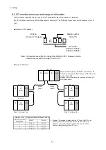
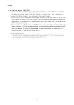
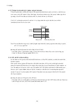
● The following settings determine the prefix and range of the allocated I/O numbers:
Prefix: The first three digits are determined by the station number setting.
Range: Numbers are automatically allocated based on the number of I/O slots in the mount base, the number
of I/O points, and the partition setting.
● I/O numbers are assigned to all slots, even those without modules installed. This means that adding or
removing modules does not cause I/O numbers to be reallocated.
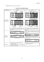
● The I/O number assigned to each input or output point is determined by the partition setting, as follows:
FREE
: Input I/O numbers (X0
AAA
) and output I/O numbers (Y0
AAA
) are both allocated, and the system
can select whichever of these I/O numbers is applicable (Table 9-4).
FIX
: I/O slots are exclusively designated for input modules or output modules. This means that each
point is assigned one I/O number, for either input or output depending on the designation of the I/O
slot. Input I/O numbers are in the format X0
AAA
, and output I/O numbers are in the format Y0
AAA
(Table 9-5).
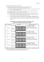
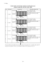
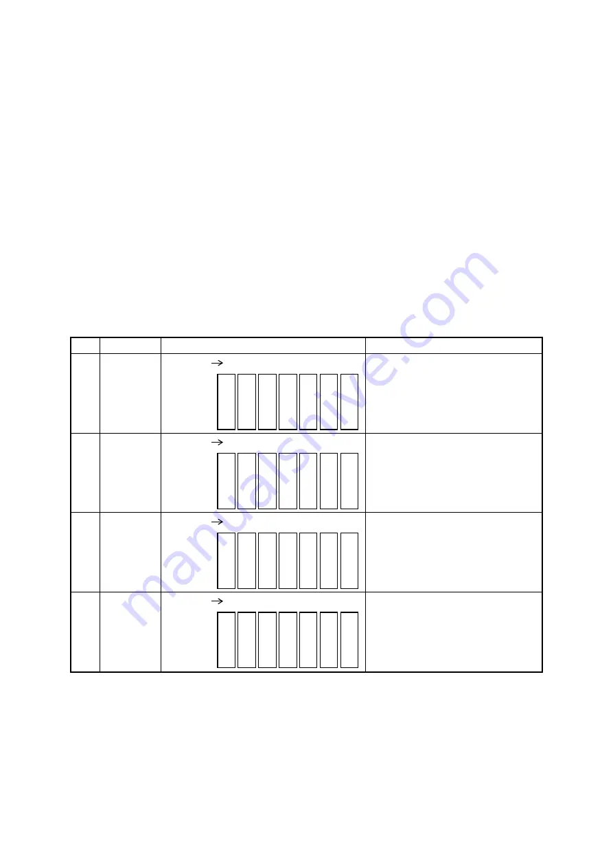
Table 9-4 CPU unit I/O number allocation and I/O points used
(Partition setting: FREE, First I/O number: 0000)
No.
I/O points
I/O numbers
I/O points used per unit
1
16 points
X area (input): 128 points
Y area (output): 128 points
Note that the first 16 points (0000 to
000F) are invalid for input and output.
2
32 points
X area (input): 256 points
Y area (output): 256 points
Note that the first 32 points (0000 to
001F) are invalid for input and output.
3
64 points
X area (input): 512 points
Y area (output): 512 points
Note that the first 64 points (0000 to
003F) are invalid for input and output.
4
128 points
X area (input): 1,024 points
Y area (output): 1,024 points
Note that the first 128 points (0000 to
007F) are invalid for input and output.
Note: Each slot is assigned input I/O numbers (X0
AAA
) and output I/O numbers (Y0
AAA
). However, this table omits
the X and Y prefixes, showing only the number component (0
AAA
).
Example: Interpret 0000 to 000F as X0000 to X000F and Y0000 to Y000F.
Slot number
I/O number
allocation
001
0
to
00
1F
002
0
to
00
2F
003
0
to
00
3F
004
0
to
00
4F
005
0
to
00
5F
006
0
to
00
6F
007
0
to
00
7F
1
2
3
4
5
6
7
Slot number
I/O number
allocation
00
2
0
to
00
3
F
00
4
0
to
00
5
F
00
6
0
to
00
7
F
00
8
0
to
00
9
F
0
0
A
0
t
o
0
0B
F
0
0
C0
to
0
0
D
F
00
E
0
to
00
F
F
1
2
3
4
5
6
7
Slot number
I/O number
allocation
00
4
0
to
00
7
F
00
8
0
to
00
B
F
00
C
0
t
o
00
F
F
0
10
0
to
0
13
F
0
14
0
to
0
17
F
0
18
0
to
0
1
BF
0
1C
0
t
o
0
1
F
F
1
2
3
4
5
6
7
Slot number
I/O number
allocation
00
8
0
to
00
F
F
0
10
0
to
0
17
F
0
18
0
to
0
1F
F
0
20
0
to
0
27
F
0
28
0
to
0
2F
F
0
30
0
to
0
37
F
0
38
0
to
0
3F
F
1
2
3
4
5
6
7
Summary of Contents for S10VE
Page 1: ...User s Manual General Description SEE 1 001 A ...
Page 2: ...User s Manual General Description ...
Page 53: ...This page is intentionally left blank ...
Page 59: ...This page is intentionally left blank ...
Page 67: ...This page is intentionally left blank ...
Page 75: ...This page is intentionally left blank ...
Page 77: ...This page is intentionally left blank ...
Page 103: ...This page is intentionally left blank ...
Page 129: ...This page is intentionally left blank ...
Page 295: ...This page is intentionally left blank ...
Page 309: ...This page is intentionally left blank ...
Page 341: ...This page is intentionally left blank ...
Page 345: ...This page is intentionally left blank ...
Page 475: ...This page is intentionally left blank ...
Page 489: ...This page is intentionally left blank ...
Page 505: ......

