10. Indicator
10-11
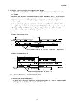
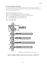
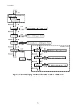
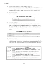
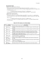
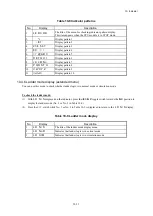
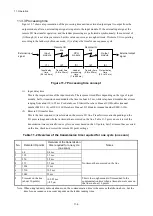
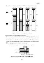
Table 10-8 Indicator patterns
No.
Display
Description
1
L E D C H K
The title of the menu for checking indicator pattern display.
This item appears when the CPU module is in STOP mode.
2
*+
Display pattern 1
3
-./01
Display pattern 2
4
2 3 4 5 6 7
Display pattern 3
5
8 9 : ; < =
Display pattern 4
6
> ? @ A B C
Display pattern 5
7
D E F G H I
Display pattern 6
8
J K L M N o
Display pattern 7
9
P Q R S T U
Display pattern 8
10
V W X Y Z
Display pattern 9
11
(All off)
Display pattern 10
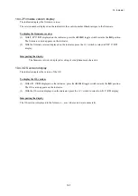
10.4.6 Ladder mode display (extended menu)
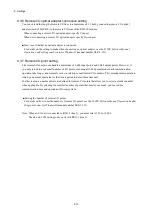
You can use this mode to check whether ladder logic is in normal mode or simulation mode.
To check the ladder mode:
(1) With
L D N / S
displayed on the indicator, press the
◄
L/
►
R toggle switch towards the
►
R position to
display the ladder mode (No. 2 or No. 3 in Table 10-9).
(2) Press the
ESC
switch while No. 2 or No. 3 in Table 10-9 is displayed to return to the
L D N / S
display.
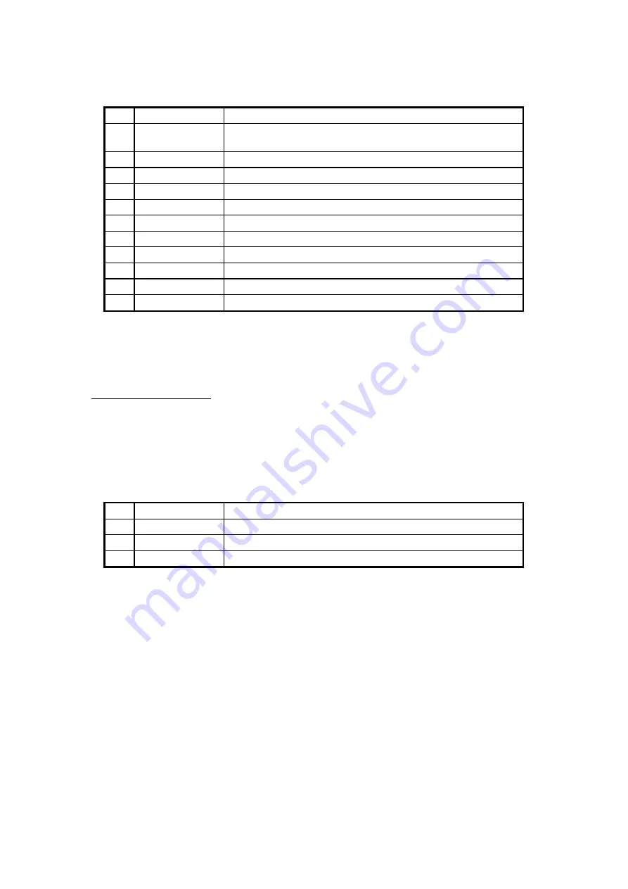
Table 10-9 Ladder mode display
No.
Display
Description
1
L D N / S
The title of the ladder mode display menu.
2
L D N o R
Indicates that ladder logic is in normal mode.
3
L D S I M
Indicates that ladder logic is in simulation mode.
Summary of Contents for S10VE
Page 1: ...User s Manual General Description SEE 1 001 A ...
Page 2: ...User s Manual General Description ...
Page 53: ...This page is intentionally left blank ...
Page 59: ...This page is intentionally left blank ...
Page 67: ...This page is intentionally left blank ...
Page 75: ...This page is intentionally left blank ...
Page 77: ...This page is intentionally left blank ...
Page 103: ...This page is intentionally left blank ...
Page 129: ...This page is intentionally left blank ...
Page 295: ...This page is intentionally left blank ...
Page 309: ...This page is intentionally left blank ...
Page 341: ...This page is intentionally left blank ...
Page 345: ...This page is intentionally left blank ...
Page 475: ...This page is intentionally left blank ...
Page 489: ...This page is intentionally left blank ...
Page 505: ......

