13. Troubleshooting
13-26
(5) Communication trace
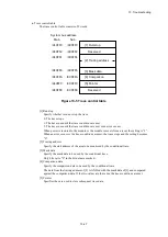
OD.RING modules have a function for tracing communicated information and content. You can use
this function when a failure occurs to generate trace data to help investigate the cause of the failure
and take corrective action.
●
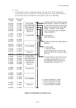
Configuration of the trace buffer
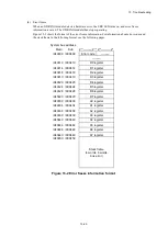
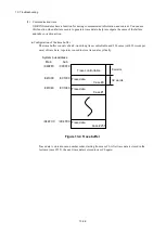
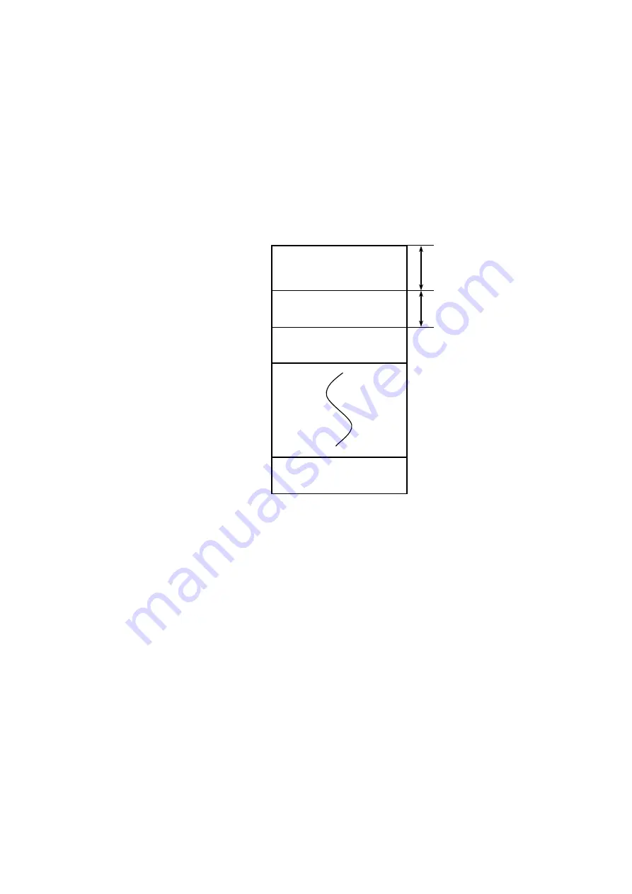
The trace buffer consists of an 8-word-long trace control table and 256 cases (with 32 words per
case) of trace data. A pointer is used to store trace data cyclically.
Figure 13-4 Trace buffer
Trace data is stored in case-number order, starting from case #0. After trace data is stored in the
last case (case #255), the next trace data is stored in case #0 again.
System bus address
Main
Sub
/9C0FF0
/9C1000
/9C1040
/9C4FC0
/940FF0
/941000
/941040
/944FC0
Trace control table
8 words
32 words
Trace data
Case #0
Trace data
Case #1
Trace data
Case #255
Summary of Contents for S10VE
Page 1: ...User s Manual General Description SEE 1 001 A ...
Page 2: ...User s Manual General Description ...
Page 53: ...This page is intentionally left blank ...
Page 59: ...This page is intentionally left blank ...
Page 67: ...This page is intentionally left blank ...
Page 75: ...This page is intentionally left blank ...
Page 77: ...This page is intentionally left blank ...
Page 103: ...This page is intentionally left blank ...
Page 129: ...This page is intentionally left blank ...
Page 295: ...This page is intentionally left blank ...
Page 309: ...This page is intentionally left blank ...
Page 341: ...This page is intentionally left blank ...
Page 345: ...This page is intentionally left blank ...
Page 475: ...This page is intentionally left blank ...
Page 489: ...This page is intentionally left blank ...
Page 505: ......

