14. Adding and Replacing Modules
14-4
14.2 CPU module (LQP600)
This section explains how to replace the CPU module.
The replacement process involves removing the existing module and installing the new one. For details on these
procedures, see
14.2.1.1
and
14.2.1.2
respectively.
14.2.1 Replacing the CPU module
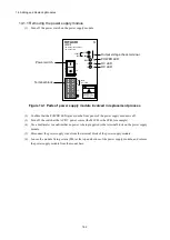
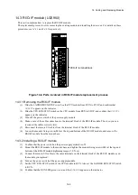
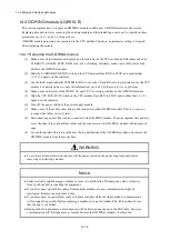
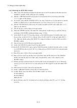
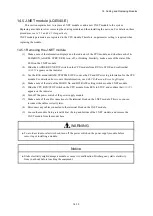
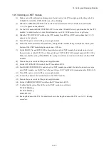
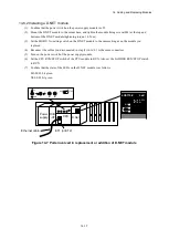
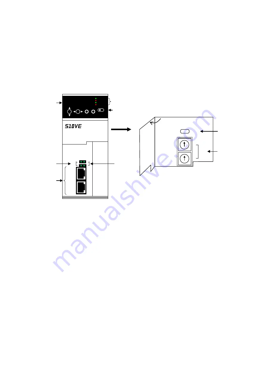
Figure 14-2 shows the parts that are involved in the CPU module replacement process.
Figure 14-2 Parts involved in CPU module replacement process
U
L
ET
ST.No.
RUN
STOP
CPU
CPU status display LEDs
LADDER RUN/STOP switch
ET1 and ET2
connectors
LINK LED
With cover
removed
CPU RUN/STOP
switch
ET ST.No.
Indicator
ALARM
ET2
ET1
2
1
ACT
1
2
LINK
LQP600
CPU
RUN
STOP
ERR
STBY
RUN
LADDER
SET
ESC
L
R
UP
DWN
C P U R U N
ACT LED
Summary of Contents for S10VE
Page 1: ...User s Manual General Description SEE 1 001 A ...
Page 2: ...User s Manual General Description ...
Page 53: ...This page is intentionally left blank ...
Page 59: ...This page is intentionally left blank ...
Page 67: ...This page is intentionally left blank ...
Page 75: ...This page is intentionally left blank ...
Page 77: ...This page is intentionally left blank ...
Page 103: ...This page is intentionally left blank ...
Page 129: ...This page is intentionally left blank ...
Page 295: ...This page is intentionally left blank ...
Page 309: ...This page is intentionally left blank ...
Page 341: ...This page is intentionally left blank ...
Page 345: ...This page is intentionally left blank ...
Page 475: ...This page is intentionally left blank ...
Page 489: ...This page is intentionally left blank ...
Page 505: ......

