xix
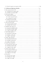
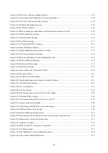
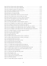
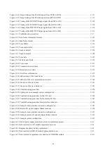
Figure 8-140 State of Restore window (when sending data) .............................................................................. 8-128
Figure 8-141 State of Restore window (when comparing data) .......................................................................... 8-128
Figure 8-142 Confirmation message for PCs number change ............................................................................ 8-129
Figure 8-143 Window for changing PCs number of restored PCs ...................................................................... 8-129
Figure 8-144 CPU RUN confirmation message ................................................................................................. 8-130
Figure 8-145 STOP recovery guidance message ................................................................................................ 8-130
Figure 8-146 State of Restore window (when no inconsistencies are found) ..................................................... 8-131
Figure 8-147 State of Restore window (when inconsistencies are found) .......................................................... 8-131
Figure 8-148 Confirmation message for overwriting comparison error data file ............................................... 8-132
Figure 8-149 CPU stop confirmation message for backup data comparison ...................................................... 8-133
Figure 8-150 Backup save data comparison window ......................................................................................... 8-134
Figure 8-151 Message asking whether to continue backup data comparison ..................................................... 8-135
Figure 8-152 State of Backup save data comparison window (during data comparison) ................................... 8-135
Figure 8-153 Confirmation message when canceling backup data comparison ................................................. 8-135
Figure 8-154 State of Backup save data comparison window (when data comparison is canceled) .................. 8-136
Figure 8-155 State of Backup save data comparison window (when no inconsistencies are found) .................. 8-136
Figure 8-156 State of Backup save data comparison window (when outputting comparison error data file) ..... 8-136
Figure 8-157 Confirmation message for overwriting comparison error data file ............................................... 8-137
Figure 8-158 Areas subject to ROM load operation ........................................................................................... 8-140
Figure 8-159 Format of operation record file ..................................................................................................... 8-143
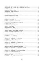
Figure 10-1 Indicator and menu keys ................................................................................................................. 10-1
Figure 10-2 Indicator display transitions when CPU module is in STOP mode ................................................. 10-3
Figure 10-3 Indicator display transitions when CPU module is in RUN mode .................................................. 10-4
Figure 10-4 Display transitions at home position ............................................................................................... 10-5
Figure 10-5 Display transitions of CPU module error status .............................................................................. 10-8
Figure 10-6 Display transitions of indicator patterns .......................................................................................... 10-10
Figure 10-7 Display transitions of E coils in ON states ...................................................................................... 10-12
Figure 11-1 User program operation (ladder and HI-FLOW individual use) ..................................................... 11-2
Figure 11-2 User program operation (ladder and HI-FLOW simultaneous use) ................................................ 11-2
Figure 11-3 Operation when the sequence cycle is longer than the program processing time ........................... 11-3
Figure 11-4 Operation when the sequence cycle is shorter than the program processing ................................... 11-3
Figure 11-5 Remote I/O connection configuration ............................................................................................. 11-4
Figure 11-6 Synchronous and asynchronous ladder operation ........................................................................... 11-5
Figure 11-7 Processing time concept .................................................................................................................. 11-6
Figure 11-8 Remote I/O transfer point settings .................................................................................................. 11-8
Figure 11-9 Output operation of the digital output module ................................................................................ 11-9
Figure 11-10 S10VE state transitions ................................................................................................................. 11-11
Figure 11-11 Example ladder program for setting the clock .............................................................................. 11-15
Summary of Contents for S10VE
Page 1: ...User s Manual General Description SEE 1 001 A ...
Page 2: ...User s Manual General Description ...
Page 53: ...This page is intentionally left blank ...
Page 59: ...This page is intentionally left blank ...
Page 67: ...This page is intentionally left blank ...
Page 75: ...This page is intentionally left blank ...
Page 77: ...This page is intentionally left blank ...
Page 103: ...This page is intentionally left blank ...
Page 129: ...This page is intentionally left blank ...
Page 295: ...This page is intentionally left blank ...
Page 309: ...This page is intentionally left blank ...
Page 341: ...This page is intentionally left blank ...
Page 345: ...This page is intentionally left blank ...
Page 475: ...This page is intentionally left blank ...
Page 489: ...This page is intentionally left blank ...
Page 505: ......

