background image

Page

CONTENTS

1. PRODUCT NAME ............................................................................................................................ 1

2. MARKETING OBJECTIVE .............................................................................................................. 1

3. APPLICATIONS  .............................................................................................................................. 1

4. SELLING POINTS ........................................................................................................................... 1

4-1. Selling Point Descriptions ................................................................................................................ 2

5. SPECIFICATIONS ........................................................................................................................... 3

6. SPECIFICATION COMPARISONS WITH SIMILAR PRODUCTS................................................... 4

7. PRECAUTIONS IN SALES PROMOTION ...................................................................................... 5

7-1. Handling Instructions ........................................................................................................................5

7-2. Precautions on Caution Plate ........................................................................................................... 5

8. DUST COLLECTION ....................................................................................................................... 6

8-1. Dust Collector ...................................................................................................................................6

8-2. To Maintain Dust Collecting Performance ......................................................................................... 6

8-3. Others ...............................................................................................................................................6

9. PRECAUTIONS IN DISASSEMBLY AND REASSEMBLY ............................................................. 7

9-1. Disassembly ..................................................................................................................................... 7

9-2. Reassembly .................................................................................................................................... 11

9-3. Wiring Procedures .......................................................................................................................... 12

9-4. Wiring Diagram ............................................................................................................................... 13

9-5. Tightening Torque ...........................................................................................................................14

9-6. Insulation Test .................................................................................................................................14

9-7. No-load Current Value ....................................................................................................................14

10. STANDARD REPAIR TIME (UNIT) SCHEDULES ...................................................................... 15

Assembly Diagram for SB 10S2

Assembly Diagram for SB 10V2

Summary of Contents for SB 10S2

Page 1: ...DATA AND SERVICE MANUAL 100 mm 4 BELT SANDER SB 10S2 SB 10V2 SPECIFICATIONS AND PARTS ARE SUBJECT TO CHANGE FOR IMPROVEMENT LIST Nos SB 10S2 0363 SB 10V2 0362 Mar 2007 S MODELS SB 10S2 SB 10V2 Hitachi Power Tools ...

Page 2: ...ICE MANUAL a symbol s is are used in the place of company name s and model name s of our competitor s The symbol s utilized here is are as follows Symbols Utilized Competitor Company Name Model Name MAKITA 9401 C2 DEWALT DW650 D2 C1 D1 9404 DW650E ...

Page 3: ...uctions 5 7 2 Precautions on Caution Plate 5 8 DUST COLLECTION 6 8 1 Dust Collector 6 8 2 To Maintain Dust Collecting Performance 6 8 3 Others 6 9 PRECAUTIONS IN DISASSEMBLY AND REASSEMBLY 7 9 1 Disassembly 7 9 2 Reassembly 11 9 3 Wiring Procedures 12 9 4 Wiring Diagram 13 9 5 Tightening Torque 14 9 6 Insulation Test 14 9 7 No load Current Value 14 10 STANDARD REPAIR TIME UNIT SCHEDULES 15 Assembl...

Page 4: ...d SB 10V2 please expand the sales of our belt sander series 3 APPLICATIONS For construction working inside working sign painting wood working furniture making etc Sanding wood and steel materials Removing old paint before repainting Preliminary sanding before painting 4 SELLING POINTS 1 020 W powerful motor Longer life drive belt Two times longer than the conventional model thanks to the wear resi...

Page 5: ...speed dial that allows the operator to adjust to the desired speed depending on applications and workpieces Dial 1 Minimum speed Dial 5 Maximum speed Dust bag 2 Clear cover Each of the Models SB 10S2 and SB 10V2 is equipped with a clear cover at the top of the body The sanding belt can be visually checked through the clear cover during operation Sanding belt Body Clear cover 3 1 020 W powerful mot...

Page 6: ...ncrete bricks and so on or painted surfaces Voltage and current 100 mm 4 Voltage V 110 120 220 230 240 Power source Type of switch AC single phase 50 60 Hz Single phase series commutator motor Type of motor Current A 9 8 9 0 4 9 4 7 4 5 Power input 1 020 W 240 to 420 m min 800 to 1 375 ft min No load belt speed Enclosure Housing Handle cover Body Dust cover Belt cover Polycarbonate resin Elastomer...

Page 7: ...Variable speed dial setting Lo 350 Hi 420 1 147 1 375 240 420 800 1 375 150 0 33 lbs 92 183 7 7 32 Dust bag 1 Sanding belt 100 x 610 4 x 24 7 3 16 1 lbs 4 7 10 3 lbs Single speed Variable speed dial setting 350 1 147 210 440 690 1 440 150 0 33 lbs 84 145 5 23 32 Dust bag 1 Sanding belt C1 C2 100 x 560 4 x 22 6 3 13 8 lbs 6 4 14 1 lbs Single speed Variable speed dial setting 350 1 147 250 380 819 1...

Page 8: ...ngers inherent in the use of any electric tool cannot be completely eliminated Accordingly general precautions and suggestions for the use of the belt sander are listed in the Handling Instructions to enhance the safe efficient use of the tool by the customer Salespersons must be thoroughly familiar with the contents of the Handling Instructions to be able to offer appropriate guidance to the cust...

Page 9: ...ng performance Instruct the customer to operate the equipment in a dry location as much as possible A clogged dust bag impairs dust collecting performance Instruct the customer to frequently clean the dust bag Overflow of dust in the dust bag impairs dust collecting performance Instruct the customer to empty the dust bag when dust has been collected to about 70 of bag capacity 8 3 Others Should sp...

Page 10: ...eplacement 9 1 Disassembly 1 Removal of the Fork Ass y 51 53 and the Idle Pulley Ass y 38 40 Fig 1 a After removing the sanding belt return the lever to its original position and remove the Knob Nut 41 43 Then loosen the two Machine Screws M4 x 14 50 52 and pull out the Fork Ass y 51 53 b After taking out the two Retaining Rings for D12 Shaft 45 47 and removing the Shaft 46 48 remove the Idle Pull...

Page 11: ... 60 62 then remove the Drive Pulley 65 67 and the Washer 43 45 g Loosen the four Tapping Screws W Flange D5 x 45 15 15 then remove the Dust Cover 16 16 from the Housing Ass y 21 21 Dust Cover 16 16 Belt Cover 14 14 Tapping Screw W Flange D5 x 45 15 15 Housing Ass y 21 21 Machine Screw W Washers M4 x 12 Black 6 6 Ball Bearing 6200VVCMPS2L 55 57 Belt 52 54 Tapping Screw W Flange D4 x 30 Black 39 41 ...

Page 12: ... 4 Removal of the Armature 4 4 Fig 4 a Loosen the two Brush Caps 27 27 and remove the two Carbon Brushes 1 Pair 26 26 b Pull out the Armature 4 4 while hitting the Housing Ass y 21 21 with a wooden mallet or plastic hammer from Pulley A 1 1 side Be careful not to crush the fan and the Dust Plate 8 8 while hitting the Housing Ass y 21 21 c Remove the Dust Plate 8 8 and the Fan Guide 9 9 d Pulley A ...

Page 13: ...0 c Remove the two Brush Terminals 12 12 from the brush holder of the Housing Ass y 21 21 d Loosen the two Hex Hd Tapping Screws D5 x 55 10 10 e Pull out the Stator Ass y 11 11 while hitting the Housing Ass y 21 21 with a wooden mallet or plastic hammer Fig 5 Stator Ass y 11 11 Housing Ass y 21 21 Tapping Screw W Flange D4 x 16 Black 29 29 Switch E 1P Screw Type W Lock 32 30 Machine Screw W Washer...

Page 14: ...Turbine Oil No 90 c When tightening the Tapping Screw W Flange D5 x 45 15 15 through the Dust Cover 16 16 into the Housing Ass y 21 21 Fig 6 match B portion of the Dust Plate 8 8 with A portion of the Dust Cover 16 16 as shown in Fig 7 Pay attention not to crush the Dust Plate 8 8 with the ribs Fig 6 Housing Ass y 21 21 Armature 4 4 Pulley A 1 1 Dust Cover 16 16 Dust Plate 8 8 Fan Guide 9 9 Fig 7 ...

Page 15: ... not to crush the lead wires by putting them between the housing and the handle cover Figs 8 a and b Switch E 1P Screw Type W Lock 32 Fig 8 a Model SB 10S2 b Model SB 10V2 Switch E 1P Screw Type W Lock 30 Controller 35 Connector 50091 31 ...

Page 16: ... 13 Fig 9 9 4 Wiring Diagram Wiring should be done in accordance with Figs 9 a and b a Model SB 10S2 b Model SB 10V2 ...

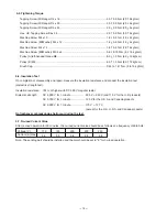
Page 17: ...V Current A max 110 5 4 120 5 0 220 2 8 230 2 9 240 2 8 9 6 Insulation Test On completion of disassembly and repair measure the insulation resistance and conduct the insulation test dielectric strength test Insulation resistance 7 M Ω or higher with DC 500 V megohm tester Dielectric strength AC 4 000 V for 1 minute 220 V 240 V and 110 V for the U K products AC 3 750 V for 1 minute 120 V for the U ...

Page 18: ...in 50 Body Ass y Belt Pulley B Belt Cover Pinion Gear Cover Ball Bearing 6200VV Drive Pulley Gear Pulley Cover General Assembly SB 10S2 Dust Cover Clear Cover Shoe Cushion Shoe Plate Fork Ass y Handle Cover Switch E Cord Housing Ass y Armature Ass y Ball Bearing 6000VV Ball Bearing 608VV Pulley A Stator Ass y ...

Page 19: ...ley B Belt Cover Pinion Gear Cover Ball Bearing 6200VV Drive Pulley Gear Pulley Cover General Assembly SB 10V2 Dust Cover Clear Cover Shoe Cushion Shoe Plate Fork Ass y Handle Cover Switch E Controller Cord Housing Ass y Armature Ass y Ball Bearing 6000VV Ball Bearing 608VV Pulley A Stator Ass y ...

Page 20: ...0S2 2007 3 26 E1 Hitachi Power Tools 1 2 3 4 5 7 9 10 11 39 14 16 17 18 19 20 33 21 22 23 25 26 27 42 40 47 48 37 38 45 46 49 51 50 52 53 54 55 56 57 50 58 59 60 61 63 62 64 65 66 13 12 24 29 15 A A 61 37 36 48 6 29 6 28 41 44 43 45 43 30 8 32 31 34 35 36 6 501 ...

Page 21: ...FLANGE D5X45 4 16 327 740 DUST COVER 1 17 327 760 HANDLE COVER 1 18 984 750 TAPPING SCREW W FLANGE D4X16 2 19 937 631 CORD CLIP 1 20 958 049 CORD ARMOR D8 2 1 20 940 778 CORD ARMOR D10 7 1 21 327 759 HOUSING ASS Y 1 INCLUD 22 25 22 938 477 HEX SOCKET SET SCREW M5X8 2 23 500 247Z CORD 1 CORD ARMOR D8 2 23 500 234Z CORD 1 CORD ARMOR D8 2 FOR GBR FIN DEN SWE NOR 23 500 432Z CORD 1 CORD ARMOR D8 2 FOR...

Page 22: ... 48 949 216 MACHINE SCREW M4X10 10 PCS 3 49 953 063 SPRING 1 50 949 218 MACHINE SCREW M4X14 10 PCS 5 51 995 585 FORK ASS Y 1 INCLUD 49 52 327 741 BELT 1 53 327 749 PULLEY B 1 54 327 748 GEAR COVER 1 55 620 0VV BALL BEARING 6200VVCMPS2L 1 56 327 750 PINION 1 57 935 522 METAL 1 58 939 540 RETAINING RING FOR D10 SHAFT 10 PCS 1 59 995 576 GEAR 1 60 948 213 WASHER B D19 1 61 953 175 METAL D10X14X12 2 6...

Page 23: ...558 SANDING BELTS 100X610 AA40 10 PCS 1 609 995 559 SANDING BELTS 100X610 AA60 10 PCS 1 610 995 560 SANDING BELTS 100X610 AA80 10 PCS 1 611 995 561 SANDING BELTS 100X610 AA100 10 PCS 1 612 995 562 SANDING BELTS 100X610 AA120 10 PCS 1 613 995 563 SANDING BELTS 100X610 AA150 10 PCS 1 614 995 564 SANDING BELTS 100X610 AA180 10 PCS 1 615 995 565 SANDING BELTS 100X610 AA240 10 PCS 1 616 995 566 SANDING...

Page 24: ... 2007 3 26 E1 Hitachi Power Tools 1 2 3 4 5 8 9 10 11 41 14 16 17 18 19 20 36 30 31 21 22 23 25 26 27 44 42 6 49 50 38 39 40 47 48 51 53 52 54 55 56 57 58 59 52 60 61 62 63 65 64 66 67 68 35 13 12 24 29 15 A A 63 39 38 50 6 29 6 28 43 46 45 47 45 34 37 501 32 33 7 ...

Page 25: ...UST COVER 1 17 327 760 HANDLE COVER 1 18 984 750 TAPPING SCREW W FLANGE D4X16 2 19 937 631 CORD CLIP 1 20 958 049 CORD ARMOR D8 2 1 21 327 759 HOUSING ASS Y 1 INCLUD 22 25 22 938 477 HEX SOCKET SET SCREW M5X8 2 23 500 234Z CORD 1 CORD ARMOR D8 2 23 500 247Z CORD 1 CORD ARMOR D8 2 FOR FIN DEN SWE NOR 23 500 439Z CORD 1 CORD ARMOR D8 2 FOR AUS NZL 23 500 435Z CORD 1 CORD ARMOR D8 2 FOR GBR 23 500 44...

Page 26: ...D12 SHAFT 10 PCS 2 48 995 587 SHAFT 1 49 327 746 STRIKING GUIDE 1 50 949 216 MACHINE SCREW M4X10 10 PCS 3 51 953 063 SPRING 1 52 949 218 MACHINE SCREW M4X14 10 PCS 5 53 995 585 FORK ASS Y 1 INCLUD 51 54 327 741 BELT 1 55 327 749 PULLEY B 1 56 327 748 GEAR COVER 1 57 620 0VV BALL BEARING 6200VVCMPS2L 1 58 327 750 PINION 1 59 935 522 METAL 1 60 939 540 RETAINING RING FOR D10 SHAFT 10 PCS 1 61 995 57...

Page 27: ...558 SANDING BELTS 100X610 AA40 10 PCS 1 609 995 559 SANDING BELTS 100X610 AA60 10 PCS 1 610 995 560 SANDING BELTS 100X610 AA80 10 PCS 1 611 995 561 SANDING BELTS 100X610 AA100 10 PCS 1 612 995 562 SANDING BELTS 100X610 AA120 10 PCS 1 613 995 563 SANDING BELTS 100X610 AA150 10 PCS 1 614 995 564 SANDING BELTS 100X610 AA180 10 PCS 1 615 995 565 SANDING BELTS 100X610 AA240 10 PCS 1 616 995 566 SANDING...

Page 28: ......

Reviews: