Rev. 3.0, 04/02, page 550 of 1064
14.6
Configuration of the DMAC (SH7751R)
14.6.1
Block Diagram of the DMAC
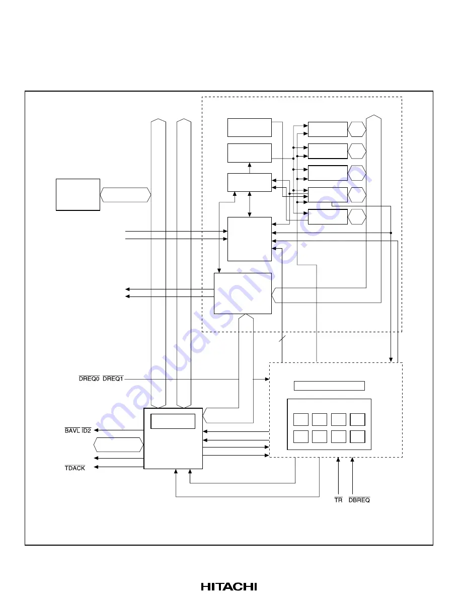
Figure 14.53 is a block diagram of the DMAC in the SH7751R.
dreq0–7
Request
8
dmaqueclr0-7
queclr0–7
SAR0, DAR0, DMATCR0,
CHCR0 only
DDTMODE
BAVL
48 bits
CH0
CH1
CH2
CH3
CH4
CH5
CH6
CH7
Request controller
DTR command buffer
DDT module
DDTD
External bus
tdack
id[2:0]
ID[1:0]
D[31:0]
DBREQ
/
SAR0–7
DAR0–7
DMATCR0–7
CHCR0–7
DMAOR
Bus
interface
P
e
ripher
al b
u
s
Inter
nal b
u
s
DMAC module
Count control
Registr control
Activation
control
Request
priority
control
32B data
buffer
Bus state
controller
On-chip
peripheral
module
Exter
nal address/on-chip
per
ipher
al module address
TMU
SCI, SCIF
DACK0, DACK1
DRAK0, DRAK1
,
DMAOR:
SAR:
DAR:
DMATCR:
CHCR:
DMAC operation register
DMAC source address register
DMAC destination address register
DMAC transfer count register
DMAC channel control register
Figure 14.53 Block Diagram of the DMAC
Summary of Contents for SH7751
Page 39: ...Rev 3 0 04 02 page xxxviii of xxxviii ...
Page 89: ...Rev 3 0 04 02 page 50 of 1064 ...
Page 157: ...Rev 3 0 04 02 page 118 of 1064 ...
Page 193: ...Rev 3 0 04 02 page 154 of 1064 ...
Page 225: ...Rev 3 0 04 02 page 186 of 1064 ...
Page 253: ...Rev 3 0 04 02 page 214 of 1064 ...
Page 301: ...Rev 3 0 04 02 page 262 of 1064 ...
Page 343: ...Rev 3 0 04 02 page 304 of 1064 ...
Page 607: ...Rev 3 0 04 02 page 568 of 1064 ...
Page 671: ...Rev 3 0 04 02 page 632 of 1064 ...
Page 745: ...Rev 3 0 04 02 page 706 of 1064 ...
Page 767: ...Rev 3 0 04 02 page 728 of 1064 ...
Page 1061: ...Rev 3 0 04 02 page 1022 of 1064 NMI tNMIL tNMIH Figure 23 69 NMI Input Timing ...
Page 1069: ...Rev 3 0 04 02 page 1030 of 1064 ...
Page 1103: ...Rev 3 0 04 02 page 1064 of 1064 ...


