5-4
Chapter 5
Installation and Configuration
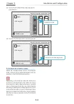
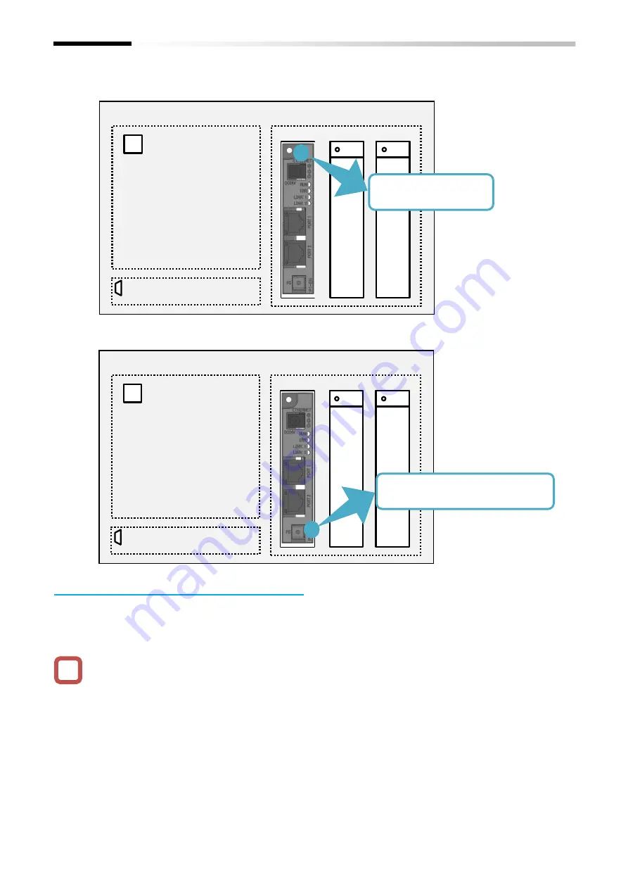
(3)
Secure the P1-EN with the screw removed in
procedure (1).
(4)
Connect the FG terminal to functional ground.
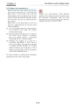
5.4 Attach the ferrite cores
Attach the included ferrite cores to the Ethernet
cable. These cores should be attached as close as
possible to the P1-EN RJ-45 connection.
Depending on the Ethernet cable the ferrite core
cannot be correctly fixed to the cable and it may
slip along the cable, despite having an anti-slip
claw. In these cases the ferrite core can be fixed by
attaching something like a clamping band or a wire
to the Ethernet cable on one or both sides of the
ferrite core. Keep in mind that the cores should be
attached as close as possible to the P1-EN RJ-45
connection.
!
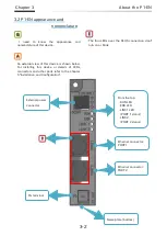
Option cassette connection slots
VOP keypad
RJ45
USB(micro-B)
SLOT1 SLOT2 SLOT3
Fasten the screw.
Option cassette connection slots
VOP keypad
RJ45
USB(micro-B)
SLOT1 SLOT2 SLOT3
Connect to functional ground.
Summary of Contents for SJ-P1 Series
Page 9: ...C 3 Table of Contents Memo ...
Page 17: ...1 8 Chapter 1 Safety Precautions Memo ...
Page 21: ...2 4 Chapter 2 Overview Memo ...
Page 25: ...3 4 Chapter 3 About the P1 EN Memo ...
Page 29: ...4 4 Chapter 4 Enclosed Items Memo ...
Page 45: ...6 8 Chapter 6 Inverter Settings Memo ...

