5-7
Chapter 5
Installation and Configuration
5.6.3
External power supply (optional)
Control circuits both the inverter and this device
can be powered up by using external input DC24V.
However, this function is not indispensable for
operating this device.
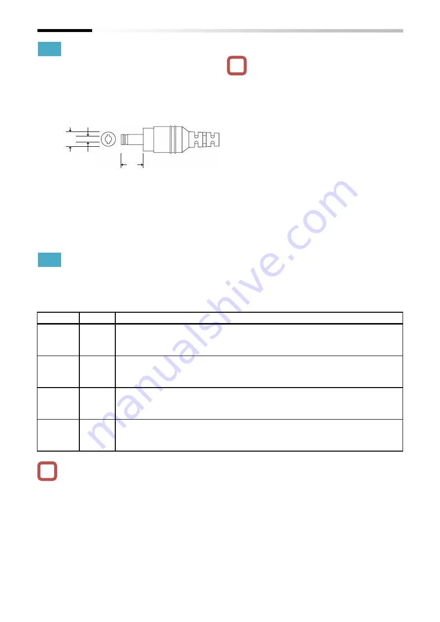
The input plug external view is shown below.
For preventing electric shock, use a power source
insulated from primary voltage which conform with
the IEC/EN 61800-5-1 SELV.
5.6.4
LED
The P1-EN LEDs show the status of this device,
details in the table below.
■
LED definition
・When powered on this device, the RUN LED
blinks first. After link established, the RUN LED
turns on.
・It takes about 1 minute for the link established
after the inverter powered on. In the meantime,
all LEDs turn off.
It can always be supplied by the external power
source. When using the external power, connect
the cable, so it minimizes the tension and stress
over the connector.
External power source specification:
DC24V±10% and 2A or more are required.
LED
Color
Description
RUN
Green
Light off: P1-EN initializing
Blinking: Link in preparation
Light on: Link established the Ethernet communication
ERR
Red
Light off: No problem detected
Blinking: Setting error in the inverter configuration related with the Ethernet
Light on: There is a problem with the Ethernet connection
LINK1
Green
Light off: Link not established the PORT1
Light on: Link established the PORT1
Blinking: In preparation, link the PORT1 to the network
LINK2
Green
Light off: Link not established the PORT2
Light on: Link established the PORT2
Blinking: In preparation, link the PORT2 to the network
!
!
9.5
2.1
5.5
Plug type: PL03B
Polar characteristic: inner side (center) has positive.
Summary of Contents for SJ-P1 Series
Page 9: ...C 3 Table of Contents Memo ...
Page 17: ...1 8 Chapter 1 Safety Precautions Memo ...
Page 21: ...2 4 Chapter 2 Overview Memo ...
Page 25: ...3 4 Chapter 3 About the P1 EN Memo ...
Page 29: ...4 4 Chapter 4 Enclosed Items Memo ...
Page 45: ...6 8 Chapter 6 Inverter Settings Memo ...

