7-6
Chapter 7
About the Modbus TCP
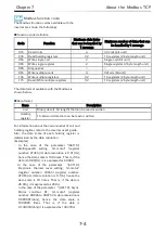
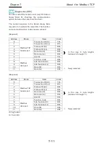
[Response]
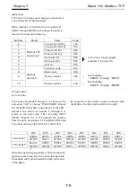
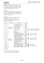
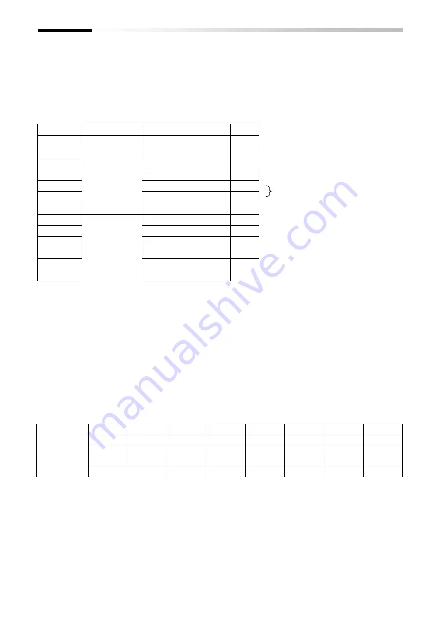
The coils in the response message are packed as
one coil per bit of the data field.
When reading 15 coils with the coil number of
0001h through 000Fh (in the above request), it
returns the codes the following.
Hi: high order
Lo: low order
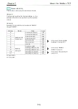
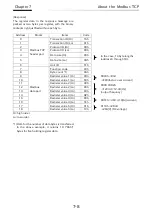
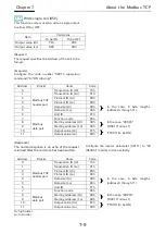
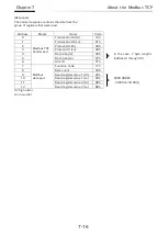
The status of outputs 8 through 1 is shown as the
byte value "40h", or binary "0100 0000b". Output
8 is the MSB of this byte, and output 1 is the LSB.
Likewise, the status of outputs F through 9 is
shown as the byte value "12h", or binary "0001
0010b". Output F is in the seventh bit position
from the right, and output F is the MSB of this byte.
The one remaining high order bit is zero filled.
↑
If the returned output quantity is not a multiple of
eight, the remaining bits in the final data byte will
be padded with zeros (toward the high order end
of the byte).
By convention, bits within a byte are shown with
the MSB to the left, and the LSB to the right.
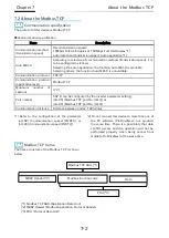
Address
Blocks
Items
Code
0
Modbus TCP
header part
Transaction ID (Hi)
15h
1
Transaction ID (Lo)
01h
2
Protocol ID (Hi)
00h
3
Protocol ID (Lo)
00h
4
Data size (Hi)
00h
In the case, 5 byte lengths
(address 6 through 10).
5
Data size (Lo)
05h
6
Unit ID
FFh
7
Modbus
data part
Function code
01h
8
Byte conut
02h
9
Output status 1
40h
←
Coil number:
“0008h”through“0001h”
10
Output status 2
12h
←
Coil number:
“000Fh”through“0009h”
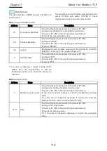
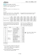
Bit7
Bit6
Bit5
Bit4
Bit3
Bit2
Bit1
Bit0
Coil status 1
0008h
0007h
0006h
0005h
0004h
0003h
0002h
0001h
OFF(0)
ON(1)
OFF(0)
OFF(0)
OFF(0)
OFF(0)
OFF(0)
OFF(0)
Coil status 2
Remain
000Fh
000Eh
000Dh
000Ch
000Bh
000Ah
0009h
OFF(0)
OFF(0)
OFF(0)
ON(1)
OFF(0)
OFF(0)
ON(1)
OFF(0)
Summary of Contents for SJ-P1 Series
Page 9: ...C 3 Table of Contents Memo ...
Page 17: ...1 8 Chapter 1 Safety Precautions Memo ...
Page 21: ...2 4 Chapter 2 Overview Memo ...
Page 25: ...3 4 Chapter 3 About the P1 EN Memo ...
Page 29: ...4 4 Chapter 4 Enclosed Items Memo ...
Page 45: ...6 8 Chapter 6 Inverter Settings Memo ...

