


INSTRUCTION MANUAL
Thank you for purchase of “HITACHI INVERTER”. This manual
explains about treatment of “SJ-PB(T) (Profibus-DP Option)”. By
reading this manual and an instruction manual of inverter use practically
for installation, maintenance, and inspection. After reading this manual,
keep it handy for future reference.
Make sure to reach this manual to the end user.
Table of Contents
Chapter1 INTRODUCTION 1
Chapter2 INSTALLATION 5
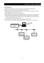
Chapter3 WIRING, CONNECTING 6
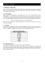
Chapter4 SETTING 8
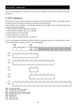
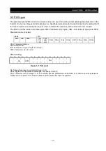
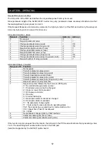
Chapter5 OPERATING 10
Chapter6 COUNTERMASURE FOR ABNORMALIT 21
Appendix PARAMETER CROSS-REFERENCE LIST 22
SJ300/L300P SERIES
SJ-PB(T)
(Profibus‑DP Option
Profibus‑DP Option
Profibus‑DP Option
Profibus‑DP Option)
NB622BX
Hitachi Inverter
After reading this manual, keep it at handy for future reference.


