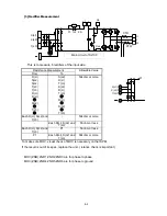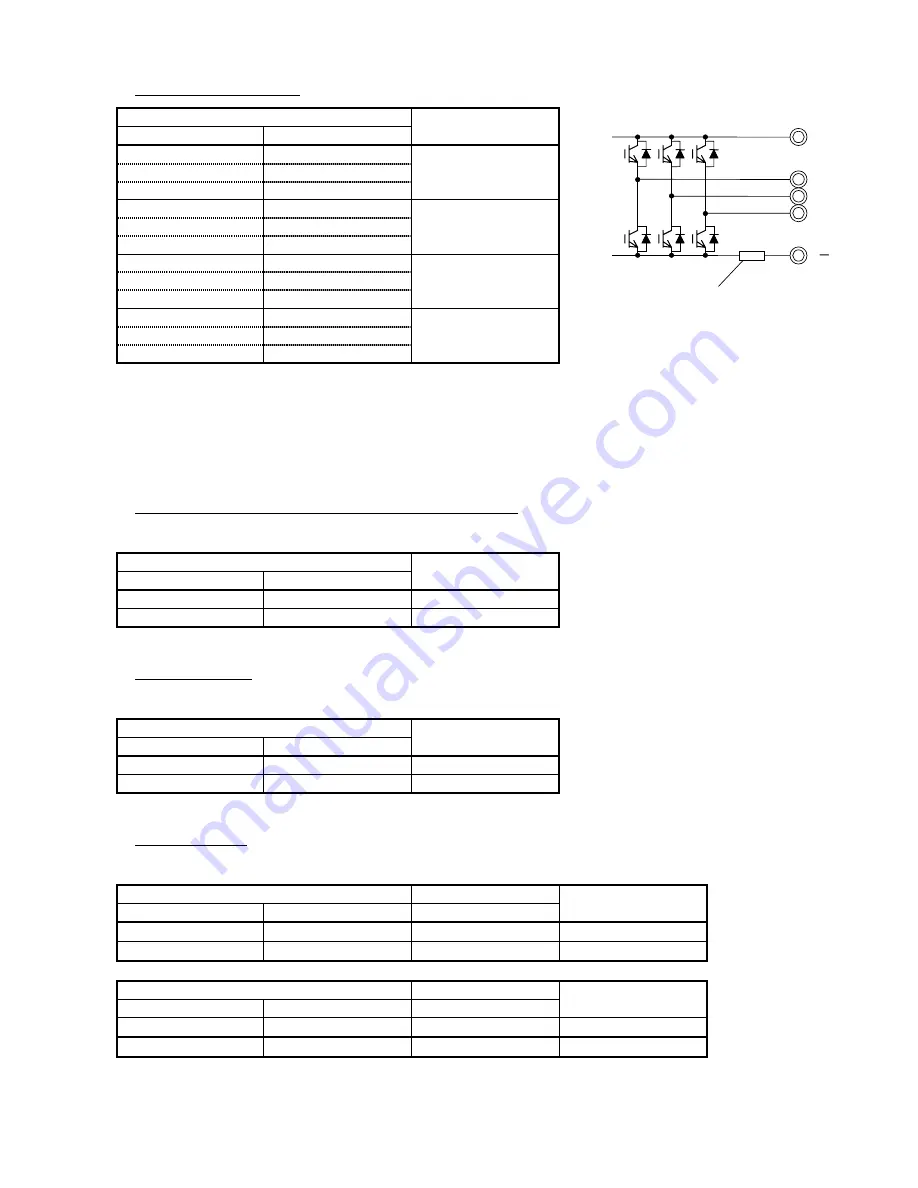
[4] IGBT Measurement
Resistance Measurement
Allowable Value
From
To
+
U
50kohm or more
+
V
+
W
U
+
50 ohm or less
V
+
W
+
-
U
50 ohm or less
-
V
-
W
U
-
50kohm or more
V
-
W
-
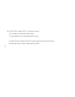
If the result is out of its spec, replace the unit.
Please note that this cannot cover 100% to find IGBT failure because if the power devices in failure,
sometimes you can find the failure in components while they are activated. (You cannot find the failure
while they are not activated.)
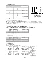
[5] Cooling FAN voltage circuit in the ISPM (PV 24N)
Check
“
b92
”
is preset
“”
00 (FAN to be worked) and disconnect the cooling FAN
Resistance Measurement
Allowable Value
From
To
Pin(up) (Red)
Pin(down) (Black)
20kohm or more
Pin(up) (Black)
Pin(down) (Red)
50ohm or less
( relative check is important )
[6] Cooling FAN
Disconnect the cooling FAN and measure impedance of FAN circuit.
Resistance Measurement
Allowable Value
From
To
Red wire
Black wire
50kohm or less
Black wire
Red wire
100kohm or more
( relative check is important )
[7] BRD(RB,+,-)
Disconnect BRD resistor.
Red wire, Black wire mean tester
’
s wires.
Resistance Measurement
Allowable Value
Allowable Value
+
RB
Diode drop V
Black wire
Red wire
100kohm - 400kohm
0.3 – 0.5
Red wire
Black wire
8ohm – 14ohm
OL
(only reference)
Resistance Measurement
Allowable Value
Allowable Value
RB
-
Diode drop V
Black wire
Red wire
100kohm – 700kohm
OL(initial charge)
Red wire
Black wire
2kohm – 4kohm
OL
(only reference)
6-3/E
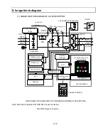
DC current detecting
resistor (shunt resistor)
(Order of mili ohm)
+
U
W
V
Rsh
Summary of Contents for SJ100 Series
Page 3: ...Revisions Revision history table No Revision contents Date of issue Manual No ⅰⅰ ...
Page 40: ......
Page 56: ......
Page 57: ......
Page 58: ......
Page 59: ......
Page 60: ......
Page 61: ......
Page 62: ......
Page 63: ......
Page 64: ......
Page 65: ......
Page 66: ......
Page 67: ......
Page 68: ......
Page 69: ......
Page 70: ......
Page 71: ......
Page 72: ......
Page 73: ......
Page 74: ......
Page 75: ...End of page ...

