


Operations and Monitoring
32
Operations and Monitoring
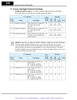
This section covers new or modified intelligent terminal functions for SJ100DN
DeviceNet Series inverters, corresponding to Chapter 4, “Operations and Monitoring,” in
the SJ100 Inverter Instruction Manual.
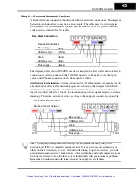
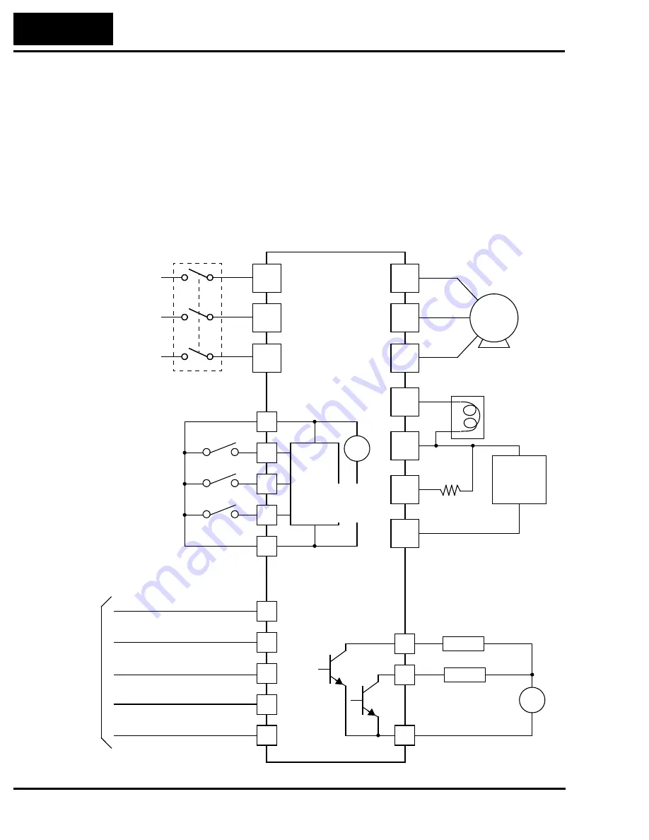
Example Wiring Diagram
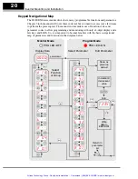
The SJ100DN DeviceNet Series inverters have fewer intelligent I/O terminals and are
without analog I/O and relay outputs, in comparison to the standard SJ100 inverters. An
example wiring diagram for SJ100DN is shown below. The DeviceNet interface wiring
is discussed in detail in “Step 2 – Connect Network Devices” on page 43.
12
11
1
2
3
L
D
CL
V+
CM2
SJ100DN
P24
Open collector outputs
CANbus High
Power source,
3-phase or
1-phase, per
inverter model
R
(L1)
S
(L2)
T
N(L3)
U
(T1)
V
(T2)
W
(T3)
Motor
[FW]
[STP]
Intelligent inputs,
3 terminals
CANbus Low
Drain
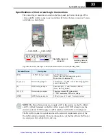
NOTE:
For the wir-
ing of intelligent I/O,
be sure to use
twisted pair /
shielded cable.
Attach the shield wire
for each signal to its
respective common
terminal at the
inverter end only.
Bus supply –
Load
Alarm signal
Run signal
Load
+
–
Logic output common
Input
circuits
[3] configurable
discrete inputs
Logic input common
+
–
24V
+1
+
RB
–
Braking
resistor (optional)
Braking
unit
(optional)
DC reactor
(optional)
Output
circuits
Breaker,
MCCB or GFI
V–
CH
Bus
DeviceNet interface
(Bare)
(Red)
(White)
(Blue)
(Black)
[EXT]
Artisan Technology Group - Quality Instrumentation ... Guaranteed | (888) 88-SOURCE | www.artisantg.com


