background image

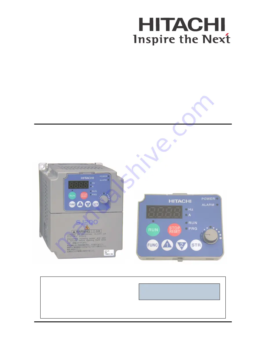
SJ200 Series Inverter 
Instruction Manual

• Single-phase Input 200V Class
• Three-phase Input 200V Class
• Three-phase Input 400V Class

After reading this manual,

keep it handy for future reference.

Hitachi Industrial Equipment Systems Co., Ltd.

Manual Number: NB650XA

March 2004

Cover

Summary of Contents for SJ200 Series

Page 1: ...anual Single phase Input 200V Class Three phase Input 200V Class Three phase Input 400V Class After reading this manual keep it handy for future reference Hitachi Industrial Equipment Systems Co Ltd Manual Number NB650XA March 2004 Cover ...

Page 2: ...res are described in CAUTION as well as WARNING so be sure to observe them 1 Step 1 Indicates a step in a series of action steps required to accomplish a goal The number of the step will be contained in the step symbol NOTE Notes indicate an area or subject of special merit emphasizing either the product s capabilities or common errors in operation or maintenance TIP Tips give a special instructio...

Page 3: ...signed to protect against personal injury WARNING HAZARD OF ELECTRICAL SHOCK DISCONNECT INCOMING POWER BEFORE WORKING ON THIS CONTROL WARNING Wait at least five 5 minutes after turning OFF the input power supply before performing maintenance or an inspection Otherwise there is the danger of electric shock CAUTION These instructions should be read and clearly understood before working on SJ200 seri...

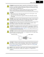
Page 4: ...nected CAUTION Hazardous main terminals for any interconnection motor contact breaker filter etc must be inaccessible in the final installation CAUTION This equipment should be installed in IP54 or equivalent see EN60529 enclosure The end application must be in accordance with BS EN60204 1 Refer to the section Choosing a Mounting Location on page 2 10 The diagram dimensions are to be suitably amen...

Page 5: ... tions Tables Otherwise it may fall and cause injury to personnel 2 10 CAUTION Be sure to install the unit on a perpendicular wall that is not subject to vibration Otherwise it may fall and cause injury to personnel 2 10 CAUTION Be sure not to install or operate an inverter that is damaged or has missing parts Otherwise it may cause injury to personnel 2 10 CAUTION Be sure to install the inverter ...

Page 6: ...njury to personnel 2 17 WARNING Make sure the input power to the inverter is OFF If the drive has been powered leave it OFF for five minutes before continuing 2 23 CAUTION Fasten the screws with the specified fastening torque in the table below Check for any loosening of screws Otherwise there is the danger of fire 2 19 CAUTION Be sure that the input voltage matches the inverter specifica tions Si...

Page 7: ...e these components properly each must have the capacity for rated current and voltage Otherwise there is the danger of fire 2 21 CAUTION The heat sink fins will have a high temperature Be careful not to touch them Otherwise there is the danger of getting burned 2 24 CAUTION The operation of the inverter can be easily changed from low speed to high speed Be sure to check the capability and limitati...

Page 8: ...not to operate electrical equipment with wet hands Otherwise there is the danger of electric shock 4 3 WARNING While the inverter is energized be sure not to touch the inverter terminals even when the motor is stopped Otherwise there is the danger of electric shock 4 3 WARNING If the Retry Mode is selected the motor may suddenly restart after a trip stop Be sure to stop the inverter before approac...

Page 9: ... prevent injury to personnel 4 24 CAUTION The heat sink fins will have a high temperature Be careful not to touch them Otherwise there is the danger of getting burned 4 2 CAUTION The operation of the inverter can be easily changed from low speed to high speed Be sure check the capability and limitations of the motor and machine before operating the inverter Otherwise it may cause injury to personn...

Page 10: ... Make sure that only qualified personnel will perform maintenance inspection and part replacement Before starting to work remove any metallic objects from your person wristwatch bracelet etc Be sure to use tools with insulated handles Otherwise there is a danger of electric shock and or injury to personnel 6 2 WARNING Never remove connectors by pulling on its wire leads wires for cooling fan and l...

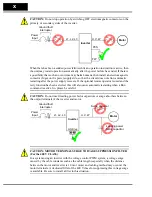
Page 11: ...hen a Run command is active So please be careful CAUTION Do not insert leading power factor capacitors or surge absorbers between the output terminals of the inverter and motor CAUTION MOTOR TERMINAL SURGE VOLTAGE SUPPRESSION FILTER For the 400 V CLASS In a system using an inverter with the voltage control PWM system a voltage surge caused by the cable constants such as the cable length especially...

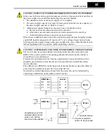
Page 12: ...er supply side Also where the effects of an indirect lightning strike are possible install a lightning conductor CAUTION SUPPRESSION FOR NOISE INTERFERENCE FROM INVERTER The inverter uses many semiconductor switching elements such as transistors and IGBTs Thus a radio receiver or measuring instrument located near the inverter is susceptible to noise interference To protect the instruments from err...

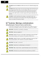
Page 13: ... originally and operate it according to the instruction manual UL Cautions Warnings and Instructions Wiring Warnings for Electrical Practices and Wire Sizes The Warnings and instructions in this section summarize the procedures necessary to ensure an inverter installation complies with Underwriters Laboratories guidelines WARNING Use 60 75 C Cu wire only or equivalent WARNING Open Type Equipment W...

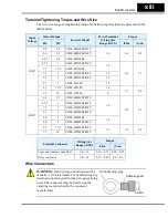
Page 14: ...t lbs N m 200V 0 2 1 4 SJ200 002NFEF NFU 16 0 6 0 8 0 4 1 2 SJ200 004NFEF NFU 0 55 3 4 SJ200 005NFEF 0 75 1 SJ200 007NFEF NFU 14 0 9 1 2 1 1 1 1 2 SJ200 011NFEF 1 5 2 SJ200 015NFEF NFU 12 2 2 3 SJ200 022NFEF NFU 10 3 7 5 SJ200 037LFU 12 5 5 7 1 2 SJ200 055LFU 10 1 5 2 0 7 5 10 SJ200 075LFU 8 400V 0 4 1 2 SJ200 004HFEF HFU 16 0 9 1 2 0 75 1 SJ200 007HFEF HFU 1 5 2 SJ200 015HFEF HFU 2 2 3 SJ200 022H...

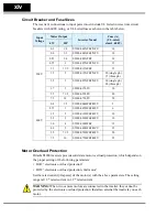
Page 15: ...When two or more motors are connected to the inverter they cannot be protected by the electronic overload protection Install an external thermal relay on each motor Input Voltage Motor Output Inverter Model Fuse A UL rated class J 600V kW HP 200V 0 2 1 4 SJ200 002NFEF NFU 10 0 4 1 2 SJ200 004NFEF NFU 10 0 55 3 4 SJ200 005NFEF 10 0 75 1 SJ200 007NFEF NFU 15 1 1 1 1 2 SJ200 011NFEF 15 1 5 2 SJ200 01...

Page 16: ...Frequency Drives 1 12 Frequently Asked Questions 1 17 Chapter 2 Inverter Mounting and Installation Orientation to Inverter Features 2 2 Basic System Description 2 8 Step by Step Basic Installation 2 9 Powerup Test 2 23 Using the Front Panel Keypad 2 25 Chapter 3 Configuring Drive Parameters Choosing a Programming Device 3 2 Using Keypad Devices 3 3 D Group Monitoring Functions 3 6 F Group Main Pro...

Page 17: ...ions 5 3 Dynamic Braking 5 5 Chapter 6 Troubleshooting and Maintenance Troubleshooting 6 2 Monitoring Trip Events History Conditions 6 5 Restoring Factory Default Settings 6 8 Maintenance and Inspection 6 9 Warranty 6 16 Appendix A Glossary and Bibliography Glossary A 2 Bibliography A 8 Appendix B ModBus Network Communications Introduction B 2 Connecting the Inverter to ModBus B 3 Network Protocol...

Page 18: ...sue Operation Manual No Initial release of manual NB650X Feb 2004 NB650X 1 Revision A Page 4 35 Added page on internal relay operation Pages 4 37 to 4 50 Added relay drawing for outputs Index 1 6 Revised entire Index added page I 6 Other minor corrections throughout March 2004 NB650XA ...

Page 19: ... 1 914 631 0600 Fax 1 914 631 3672 Hitachi Australia Ltd Level 3 82 Waterloo Road North Ryde N S W 2113 Australia Phone 61 2 9888 4100 Fax 61 2 9888 4188 Hitachi Europe GmbH Am Seestern 18 D 40547 Düsseldorf Germany Phone 49 211 5283 0 Fax 49 211 5283 649 Hitachi Industrial Equipment Systems Co Ltd International Sales Department WBG MARIVE WEST 16F 6 Nakase 2 chome Mihama ku Chiba shi Chiba 261 71...

Page 20: ...Getting Started In This Chapter page Introduction 2 SJ200 Inverter Specifications 5 Introduction to Variable Frequency Drives 12 Frequently Asked Questions 17 1 ...

Page 21: ...rnal resistor Convenient removable keypad for parameter settings can be mounted on panel door Built in RS 485 MODBUS RTU as standard New current limit function Sixteen programmable speed levels PID control adjusts motor speed automatically to maintain a process variable value The design in Hitachi inverters overcomes many of the traditional trade offs between speed torque and efficiency The perfor...

Page 22: ... as shown part no 4X KITmini Digital Operator Copy Unit The optional digital operator copy unit part no SRW 0EX is shown to the right It has a 2 line display that shows parameters by function code and by name It has the additional capability of reading uploading the parameter settings in the inverter into its memory Then you can connect the copy unit on another inverter and write download the para...

Page 23: ... Power Input Rating frequency voltage phase current Inverter model number Motor capacity for this model Output Rating Frequency voltage current Manufacturing codes Lot number date etc Specifications label Regulatory agency approval labels opposite side SJ200 037 H F E Restricted distribution E Europe U USA R Japan Input voltage N single or three phase 200V class H three phase 400V class L three ph...

Page 24: ...y kVA 230V 0 6 1 0 1 1 1 5 1 9 240V 0 6 1 0 1 2 1 6 2 0 Rated input voltage 1 phase 200 to 240V 10 50 60 Hz 5 3 phase 200 to 240V 10 50 60 Hz 5 037LFU 055LFU and 075LFU 3 phase only Integrated EMC filter EU version Single phase filter Category C3 5 USA version Rated input current A 1 phase 3 5 5 8 6 7 9 0 11 2 3 phase 2 0 3 4 3 9 5 2 6 5 Rated output voltage 3 3 phase 200 to 240V proportional to i...

Page 25: ... voltage when using a Hitachi standard 3 phase 4 pole motor when selecting intelligent sensorless vector control iSLV Note 8 The braking torque via capacitive feedback is the average deceleration torque at the shortest deceleration stopping from 50 60 Hz as indicated It is not continuous regenerative braking torque The average deceleration torque varies with motor loss This value decreases when op...

Page 26: ... 055LFU 075LFU 3 phase only Integrated EMC filter EU version Single phase filter Category C3 5 USA version Rated input current A 1 phase 17 5 24 0 3 phase 10 0 14 0 22 0 30 0 40 0 Rated output voltage 3 3 phase 200 to 240V proportional to input voltage Rated output current A 8 0 11 0 17 5 24 32 Starting torque 7 200 or more 180 or more Dynamic braking approx torque short time stop 8 without resist...

Page 27: ...filter EU version Three phase filter Category C3 5 USA version Rated input current A 2 0 3 3 5 0 7 0 Rated output voltage 3 3 phase 380 to 480V proportional to input voltage Rated output current A 1 5 2 5 3 8 5 5 Starting torque 7 200 or more Dynamic braking approx torque short time stop 8 without resistor from 50 60 Hz 100 50Hz 50 60Hz 70 50Hz 20 60Hz with resistor 150 100 DC braking Variable ope...

Page 28: ...ed EMC filter EU version Three phase filter Category C3 USA version Rated input current A 10 0 11 0 16 5 20 0 Rated output voltage 3 3 phase 380 to 480V proportional to input voltage Rated output current A 7 8 8 6 13 16 Starting torque 7 180 or more Dynamic braking approx torque short time stop 8 without resistor from 50 60 Hz 20 50Hz 20 60Hz with resistor 100 80 DC braking Variable operating freq...

Page 29: ...to 2k Ohms 2W FWD REV Run Operator panel Run Stop Forward Reverse run change by command External signal Forward run stop Reverse run stop Intelligent input terminal FW forward run command RV reverse run command CF1 CF4 multi stage speed setting JG jog command DB external braking SET set second motor 2CH 2 stage accel decel command FRS free run stop command EXT external trip USP startup function SF...

Page 30: ... C 10 Storage 25 to 70 C 11 Humidity 20 to 90 humidity non condensing Vibration 12 5 9 m s2 0 6G 10 to 55 Hz Location Altitude 1 000 m or less indoors no corrosive gasses or dust Coating color Munsell 8 5YR6 2 0 2 Options Remote operator unit copy unit cables for the units braking unit braking resistor AC reactor DC reactor noise filter DIN rail mounting Item General Specifications Signal Contact ...

Page 31: ...the frequency of the power sent to the motor An inverter in general is a device that converts DC power to AC power The figure below shows how the variable frequency drive employs an internal inverter The drive first converts incoming AC power to DC through a rectifier bridge creating an internal DC bus voltage Then the inverter circuit converts the DC back to AC again to power the motor The specia...

Page 32: ...ty to separately control these two vectors is what allows the SJ200 to deliver extraordinary low speed performance and speed control accuracy Inverter Input and Three Phase Power The Hitachi SJ200 Series of inverters includes two sub groups the 200V class and the 400V class inverters The drives described in this manual may be used in either the United States or Europe although the exact voltage le...

Page 33: ... chassis ground to the ground connection at the bottom of the inverter housing Notice the three connections to the motor do not include one marked Neutral or Return The motor represents a balanced Y impedance to the inverter so there is no need for a separate return In other words each of the three Hot connections serves also as a return for the other connections because of their phase relationshi...

Page 34: ...icate a particu lar inverter s settings in many other inverters in assembly line fashion Braking In general braking is a force that attempts to slow or stop motor rotation So it is associ ated with motor deceleration but may also occur even when the load attempts to drive the motor faster than the desired speed overhauling If you need the motor and load to decelerate quicker than their natural dec...

Page 35: ...6 preset speeds And it can apply separate acceleration and deceleration transitions from any preset to any other preset speed A multi speed profile shown at right uses two or more preset speeds which you can select via intelligent input terminals This external control can apply any preset speed at any time Alterna tively the selected speed is infinitely variable across the speed range You can use ...

Page 36: ... setting several motor parameters either manually or through an auto tuning procedure Now iSLV uses proprietary Hitachi algorithms and high speed processing to provide smooth control that adapts to motor characteristics in real time Even the need to do auto tuning procedures has been eliminated Q Although the SJ200 inverter is a variable speed drive can I use it in a fixed speed application A Yes ...

Page 37: ...f a short in the motor that puts a hazardous voltage on its housing Secondly motors exhibit leakage currents that increase with aging Lastly a grounded chassis generally emits less electrical noise than an ungrounded one Q What type of motor is compatible with the Hitachi inverters A Motor type It must be a three phase AC induction motor Use an inverter grade motor that has 800V insulation for 200...

Page 38: ...operation of nearby electrical devices is not affected Some applications are governed by particular regulatory agencies and noise suppression is mandatory In those cases the inverter must have the corresponding noise filter installed Other applications may not need noise suppression unless you notice electrical interference with the operation of other devices Q The SJ200 features a PID loop featur...

Page 39: ...InverterMounting and Installation In This Chapter page Orientation to Inverter Features 2 Basic System Description 8 Step by Step Basic Installation 9 Powerup Test 23 Using the Front Panel Keypad 25 2 ...

Page 40: ...de a fan s to enhance heat sink performance The mounting holes are pre drilled in the heat sink for your convenience Smaller models have two mounting holes while larger ones have four Be sure to use all the mounting holes provided Two chassis GND screws are located on the metal tab on the heat sink at the bottom of the inverter Never touch the heat sink during or just after operation it can be ver...

Page 41: ...tion The RJ45 connection consists of two parts The clear plastic RJ45 modular interconnect makes the connection between the inverter and the keypad It is easily removed to allow you to plug a communications cable into the modular connector Installing the Keypad Follow these steps 1 Remember to install the RJ45 modular interconnect Otherwise there will be no connection to the keypad 2 Set the botto...

Page 42: ...over The figure below shows a typical housing cover in an upside down position to reveal the tabs The two locking tabs are the ones which you will need to press to remove the cover The two hinging tabs will allow the cover to tilt open after the locking tabs are released The figure below shows the procedure for removing the housing cover While pressing inward on the housing it is helpful to wiggle...

Page 43: ...g even when the main power to the inverter is OFF So never directly touch any terminal or circuit component The logic input connector top connector can be removed by pulling gently upward as shown below left DO NOT force the connector as damage to the circuit board may occur Try gently shifting the connector side to side while pulling if having difficulty The analog input output and logic output c...

Page 44: ...E DIP switch will work However communication with smart operator devices requires the proper setting Using digital operators such as OPE SR or OPE 0EX requires the OPE setting Inverter control via a ModBus network communication requires the 485 setting See Connecting the Inverter to ModBus on page B 3 for more details The TM PRG Terminal Program DIP switch affects the inverter s setting for contro...

Page 45: ...ng to the left separate from signal level logic or analog wiring to the right Remove the housing partition and as shown as set it aside in a secure place while wiring Never operate the inverter drive with the parti tion removed or the front housing cover removed The power input and motor 3 phase wiring connect to the lower row of terminals The upper row of power terminals connect to optional dynam...

Page 46: ... to prevent inverter damage See Warning on next page Radio noise filter Electrical noise interference may occur on nearby equipment such as a radio receiver This magnetic choke filter helps reduce radiated noise can also be used on output EMI filter for CE applications see Appendix D Reduces the conducted noise on the power supply wiring between the inverter and the power distribution system Conne...

Page 47: ...on the power supply side Also where the effects of an indirect lightning strike are possible install a lightning conductor Step by Step Basic Installation This section will guide you through the following basic steps of installation NOTE If the installation is in an EU country study the EMC installation guidelines in Appendix D Step Activity Page 1 Choose a mounting location in compliance with the...

Page 48: ...welding metal shavings dust etc Other wise there is the danger of fire CAUTION Be sure to install the inverter in a place that can bear the weight according to the specifications in the text Chapter 1 Specifications Tables Otherwise it may fall and cause injury to personnel CAUTION Be sure to install the unit on a perpendicular wall that is not subject to vibration Otherwise it may fall and cause ...

Page 49: ...ection it s a good time to temporarily cover the inverter s ventilation openings Paper and masking tape are all that is needed This will prevent harmful debris such as wire clippings and metal shavings from entering the inverter during installation Please observe this checklist while mounting the inverter 1 The ambient temperature must be in the range of 10 to 40 C 2 Keep any other heat producing ...

Page 50: ...e the applicable drawing on the following pages for your inverter Dimensions are given in millimeters inches format NOTE Some inverter housings require two mounting screws while others require four Be sure to use lock washers or other means to ensure screws do not loosen due to vibration 4 SJ200 002NFEF 002NFU ...

Page 51: ...SJ200 Inverter Inverter Mounting and Installation 2 13 Dimensional drawings continued SJ200 004NFEF 004NFU 005NFEF ...

Page 52: ...Step by Step Basic Installation Inverter Mounting and Installation 2 14 Dimensional drawings continued SJ200 007NFEF 007NFU 011NFEF 004HFEF 004HFU ...

Page 53: ...SJ200 Inverter Inverter Mounting and Installation 2 15 Dimensional drawings continued SJ200 007HFEF 007HFU ...

Page 54: ...Step by Step Basic Installation Inverter Mounting and Installation 2 16 Dimensional drawings continued SJ200 015NFEF 015NFU 022NFEF 022NFU 037LFU 015HFEF 015HFU 022HFEF 022HFU 030HFEF 040HFEF 040HFU ...

Page 55: ...cuit capable of delivering not more than 5 000 rms symmetrical amperes 480 V maximum For models with suffix H HIGH VOLTAGE Be sure to ground the unit Otherwise there is a danger of electric shock and or fire HIGH VOLTAGE Wiring work shall be carried out only by qualified personnel Other wise there is a danger of electric shock and or fire HIGH VOLTAGE Implement wiring after checking that the power...

Page 56: ...ircuit breaker to be used Note 3 Be sure to use a larger wire gauge if power line length exceeds 66 ft 20m Note 4 Use 18 AWG 0 75 mm2 wire for the alarm signal wire AL0 AL1 AL2 terminals Motor Output kW HP Inverter Model Wiring Applicable equipment kW HP Power Lines Signal Lines Fuse UL rated class J 600V 0 2 1 4 SJ200 002NFEF NFU AWG16 1 3 mm2 18 to 28 AWG 0 14 to 0 75 mm2 shielded wire see Note ...

Page 57: ... phase or three phase power All models have the same power connector terminals R L1 S L2 and T L3 So you must refer to the specifications label on the side of the inverter for the acceptable power source types For inverters that can accept single phase power and are connected that way terminal S L2 will remain unconnected The wiring example to the right shows an SJ200 inverter wired for 3 phase in...

Page 58: ...kW for NFEF NFU models Three phase 200 to 240V 50 60Hz above 2 2kW for LFU models Three phase 380 to 480 V 50 60Hz for HFEF models CAUTION Be sure not to power a three phase only inverter with single phase power Otherwise there is the possibility of damage to the inverter and the danger of fire Inverter models SJ200 002NFEF NFU to 005NFEF NFU Inverter models SJ200 007NFEF to 022NFEF 007NFU to 037L...

Page 59: ...e is the possibility to stall the switch off function through small amounts of DC current Please observe the following Use only short time invariant and pulse current sensitive ground fault interrupters with higher trigger current Other components should be secured with separate ground fault interrupters Ground fault interrupters in the power input wiring of an inverter are not an absolute protect...

Page 60: ...star ground single point arrangement and never daisy chain the grounds point to point Use the same wire gauge on the motor and chassis ground wiring as you used on the power input wiring in the previous step After completing the wiring Check the mechanical integrity of each wire crimp and terminal connection Replace the housing partition that covers access to the power connections Replace the fron...

Page 61: ...power source and motor No additional wiring of inverter connectors or terminals has been done The power supply is reliable and the motor is a known working unit and the motor nameplate ratings match the inverter ratings The motor is securely mounted and is not connected to any load Goals for the Powerup Test If there are any exceptions to the above conditions at this step please take a moment to t...

Page 62: ...e specifications with the respective manufacturer Only operate the motor at elevated frequencies after getting their approval Otherwise there is the danger of equipment damage and or injury CAUTION Check the following before and during the powerup test Otherwise there is the danger of equipment damage Is the shorting bar between the 1 and terminals installed DO NOT power or operate the inverter if...

Page 63: ...tripped Potentiometer Allows an operator to directly set the motor speed when the potenti ometer is enabled for output frequency control Potentiometer Enable LED ON when the potentiometer is enabled for value entry Parameter Display A 4 digit 7 segment display for parameters and function codes Display Units Hertz Amperes One of these LEDs will be ON to indicate the units associated with the parame...

Page 64: ...d in this manual for uniformity A to F The inverter automatically switches into Monitor Mode when you access D Group functions It switches into Program Mode when you access any other group because they all have editable parameters Error codes use the E Group and appear automatically when a fault event occurs Refer to Monitoring Trip Events History Conditions on page 6 5 for error code details Func...

Page 65: ...parame ters and functions in the diagram below You may later use this map as a reference The navigational map shows the relationship of all resources of the inverter in one view In general use the key to move left and right and the arrow keys to move up and down 1 2 2 1 Edit Write data to EEPROM Increment decrement value 2 1 2 1 2 1 2 1 2 1 2 1 1 Select Parameter Display Data 2 Return to parameter...

Page 66: ... for A001 and A002 settings to be active Other wise the keypad will be unable to accept a Run command or set the motor speed with the potentiometer If the switch setting has been changed see the DIP Switch Introduction on page 2 6 Prepare to Edit Parameters This sequence begins with powering ON the inverter then it shows how to navigate to the A Group parameters for subsequent settings You can als...

Page 67: ...LED will be ON This does not mean the motor is trying to run it means that the RUN key is now enabled DO NOT press the RUN key at this time complete the parameter setup first Action Display Func Parameter Starting point A Group selected Press the key Speed command source setting Press the key again 00 Keypad potentiometer 01 Control terminals 02 Function F001 setting 03 ModBus network 10 Calculate...

Page 68: ... Voltage Setting The inverter has an Automatic Voltage Regulation AVR function It adjusts the output voltage to match the motor s nameplate voltage rating The AVR smooths out fluctuations in the input power source but note that it does not boost the voltage in the event of a brown out Use the AVR setting A082 that most closely matches the one for your motor 200V Class 200 215 220 230 240 VAC 400V ...

Page 69: ...ting Action Display Func Parameter Starting point Base frequency setting Press the key and hold until AVR voltage select Press the key or Default values for AVR voltage 200V class 230VAC 400V class 400VAC xxxFEF 400V class 460VAC xxxFU Press the or key as needed Set to your motor specs your display may be different Press the key Stores parameter returns to A Group list Action Display Func Paramete...

Page 70: ...e the state of the PRG LED Then study the Keypad Navigational Map on page 2 27 to determine the current state of the keypad controls and display As long as you do not press the STR key no parameters will be changed by keypad entry errors Note that power cycling the inverter causes it to power up Monitor Mode displaying the value for D001 output frequency The next section will show you how to monit...

Page 71: ...e you are selecting the particular monitoring parameter The display shows the current speed is zero at this point The Hz LED will be ON indicating the display units For current the Amperes LED will be ON Running the Motor If you have programmed all the parameters up to this point you re ready to run the motor First review this checklist 1 Verify the Power LED is ON If not check the power connectio...

Page 72: ...ed to output 60 Hz at full scale Use the following formula to calculate the RPM The theoretical speed for the motor is 1800 RPM speed of torque vector rotation However the motor cannot generate torque unless its shaft turns at a slightly different speed This difference is called slip So it s common to see a rated speed of approxi mately 1750 RPM on a 60 Hz 4 pole motor Using a tachometer to measur...

Page 73: ...ing a Programming Device 2 Using Keypad Devices 3 D Group Monitoring Functions 6 F Group Main Profile Parameters 8 A Group Standard Functions 9 B Group Fine Tuning Functions 30 C Group Intelligent Terminal Functions 41 H Group Motor Constants Functions 55 3 ...

Page 74: ...nd observing their effects you can achieve a finely tuned system And the SJ200 Series inverters feature intelligent sensorless vector control iSLV to eliminate the need for manually setting motor parameters or even to do an auto tuning procedure Introduction to Inverter Programming The front panel keypad is the first and best way to get to know the inverter s capabilities Every function or program...

Page 75: ... tripped Potentiometer Allows an operator to directly set the motor speed when the potenti ometer is enabled for output frequency control Potentiometer Enable LED ON when the potentiometer is enabled for value entry Parameter Display A 4 digit 7 segment display for parameters and function codes Display Units Hertz Amperes One of these LEDs will be ON to indicate the units associated with the param...

Page 76: ...d parameter shown in the display to the inverter s EEPROM Upload or download of parameters to from external devices is accomplished through a different command do not confuse Store with Download or Upload 1 2 2 1 Edit Write data to EEPROM Increment decrement value 2 1 2 1 2 1 2 1 2 1 2 1 1 Select Parameter Display Data 2 Return to parameter list 2 1 2 1 2 1 2 1 2 1 2 1 2 1 Edit Parameter FUNC FUNC...

Page 77: ...t The parameter tables in this chapter have a column titled Run Mode Edit An Ex mark means the parameter cannot be edited a Check mark means the parameter can be edited The Software Lock Setting parameter B031 determines when the Run Mode access permission is in effect and access permission in other conditions as well It is the responsibility of the user to choose a useful and safe software lock s...

Page 78: ...n Run Mode Edit Units Func Code Name SRW Display Description D001 Output frequency monitor Real time display of output frequency to motor from 0 0 to 400 0 Hz Hz FM 0000 00Hz D002 Output current monitor Filtered display of output current to motor 100 ms internal filter time constant range is 0 to 200 of inverter rated current A Iout 0000 0A D003 Rotation direction monitor Three different indicatio...

Page 79: ...monitor Displays total time the inverter has been in RUN mode in hours Range is 0 to 9999 1000 to 9999 Γ100 to Γ999 10 000 to 99 900 hours RUN 0000000hr D017 Cumulative power on time monitor Displays total time the inverter has been in RUN mode in hours Range is 0 to 9999 1000 to 9999 Γ100 to Γ999 10 000 to 99 900 hours ON 0000000hr D Function Run Mode Edit Units Func Code Name SRW Display Descrip...

Page 80: ...rmines the direction of rotation as commanded only from the keypad This setting applies to any motor profile 1st or 2nd in use at a particular time Output frequency t 0 F002 F001 F003 F Function Run Mode Edit Defaults Func Code Name SRW Display Description FEF EU FU USA Units F001 Output frequency setting Standard default target frequency that determines constant motor speed range is 0 0 start fre...

Page 81: ...setting Five options select codes 00 Keypad potentiometer 01 Control terminal 02 Function F001 setting 03 ModBus network input 10 Calculate function output 01 00 F COM VR A002 Run command source setting Three options select codes 01 Control terminal 02 Run key on keypad or digital operator 03 ModBus network input 01 02 OPE Mode REM Code Frequency Source Refer to page s 00 Keypad potentiometer The ...

Page 82: ...RG switch setting forces terminal operation according to the table below When A001 01 and A002 01 the inverter control source is the terminals regardless of the TM PRG switch position When A001 and A002 setting is not 01 then the TM PRG switch can force terminal input control Code Run Command Source Refer to page s 01 Control terminal The FW or RV input terminals control Run Stop operation 4 12 3 ...

Page 83: ...command source The following table lists all Run command setting methods and their relative priority 1 is the highest priority Priority A001 Frequency Source Setting Method Refer to page 1 CF1 to CF4 Multi speed terminals 4 13 2 OPE Operator Control intelligent input 4 31 3 F TM intelligent input 4 33 4 AT terminal 4 23 5 TM PRG DIP Switch if switch is in TM position 3 10 6 A001 Frequency source s...

Page 84: ...ge If you want the motor to output constant torque over its entire operating range limited to the motor nameplate voltage and frequency rating then set the base frequency and maximum frequency equal as shown below right NOTE The 2nd motor settings in the tables in this chapter store an alternate set of parameters for a second motor The inverter can use the 1st set or 2nd set of parameters to gener...

Page 85: ...efines whether the inverter outputs 0Hz or the A011 specified frequency when the analog input value is less than the A013 setting When the input voltage is greater than the A014 ending value the inverter outputs the ending frequency specified by A012 Adjusting OI L characteristics In the graph to the right A103 and A104 select the active portion of the input current range Parameters A101 and A102 ...

Page 86: ...AT 01 O OI AT input is ignored 02 Select between O and keypad potentiometer 03 Select between OI and keypad potentiometer 00 00 Hz AT Slct O OI A011 Pot O L input active range start frequency The output frequency corre sponding to the analog input range starting point range is 0 0 to 400 0 0 0 0 0 Hz O EXS 0000 0Hz A012 Pot O L input active range end frequency The output frequency corre sponding t...

Page 87: ...ncy to 400 Hz A220 Speed 0 2nd motor 0 0 0 0 Hz 2SPD00s 0000 0Hz A021 to A035 Multi speed frequency settings for both motors Defines 15 more speeds range is 0 0 start frequency to 400 Hz A021 Speed 1 A035 Speed 15 see next row see next row Hz SPD 01s 000 0Hz SPD 02s 000 0Hz SPD 03s 000 0Hz SPD 04s 000 0Hz SPD 05s 000 0Hz SPD 06s 000 0Hz SPD 07s 000 0Hz SPD 08s 000 0Hz SPD 09s 000 0Hz SPD 10s 000 0...

Page 88: ...tant and Variable Reduced Torque The graph below left shows the constant torque characteristic from 0Hz to the base frequency A003 The voltage remains constant for output frequencies higher than the base frequency The graph below right shows the general variable reduced torque curve The range from 0Hz to the base frequency is the variable characteristic Manual Torque Boost The Constant and Variabl...

Page 89: ...tions Intelligent Sensorless Vector Control iSLV This advanced torque control algorithm improves torque performance at very low speeds down to 0 5 Hz as well as improve regulation across the speed range Set parameter A044 02 to select iSLV operation The iSLV algorithm automatically matches the characteristics of the particular motor connected to your inverter Auto tuning is not required The iSLV c...

Page 90: ...or control iSLV 02 02 CTRL I SLV A244 V f characteristic curve selection 2nd motor Two available V f curves three select codes 00 Constant torque 01 Reduced torque 02 Intelligent sensorless vector control iSLV 02 02 2CTRL I SLV A045 V f gain setting Sets voltage gain of the inverter range is 20 to 100 100 100 V Gain 00100 A046 Automatic torque boost voltage gain Sets torque boost voltage gain of t...

Page 91: ...page 4 25 Also refer to the motor manufacturer s specifications for duty cycle recommendations during DC braking DC braking Free run Running t 0 A053 A055 A Function Run Mode Edit Defaults Func Code Name SRW Display Description FEF EU FU USA Units A051 DC braking enable Two options select codes 00 Disable 01 Enable 00 00 DCB Mode OFF A052 DC braking frequency setting The frequency at which DC brak...

Page 92: ...limit setting Sets a limit on output frequency less than the maximum frequency A004 Range is from frequency lower limit A062 to maximum frequency A004 0 0 setting is disabled 0 1setting is enabled 0 0 0 0 Hz Lim H 0000 0Hz A261 Frequency upper limit setting 2nd motor Sets a limit on output frequency less than the maximum frequency A004 Range is from frequency lower limit A262 to maximum frequency ...

Page 93: ...values 0 A067 A065 A063 A064 A064 A066 A066 A068 A068 A Function Run Mode Edit Defaults Func Code Name SRW Display Description FEF EU FU USA Units A063 A065 A067 Jump center frequency setting Up to 3 output frequencies can be defined for the output to jump past to avoid motor resonances center frequency Range is 0 0 to 400 0 Hz 0 0 0 0 0 0 0 0 0 0 0 0 Hz JUMP F1 0000 0Hz JUMP F2 0000 0Hz JUMP F3 0...

Page 94: ... Mode Edit Defaults Func Code Name SRW Display Description FEF EU FU USA Units A071 PID Enable Enables PID function two option codes 00 PID Disable 01 PID Enable 00 00 PID Mode OFF A072 PID proportional gain Proportional gain has a range of 0 2 to 5 0 1 0 1 0 PID P 0001 0 A073 PID integral time constant Integral time constant has a range of 0 0 to 150 seconds 1 0 1 0 sec PID I 0001 0s A074 PID der...

Page 95: ...er than the power input voltage If you enable this feature be sure to select the proper voltage class setting for your motor A Function Run Mode Edit Defaults Func Code Name SRW Display Description FEF EU FU USA Units A081 AVR function select Automatic output voltage regulation selects from three type of AVR functions three option codes 00 AVR enabled 01 AVR disabled 02 AVR enabled except during d...

Page 96: ...input Transition via freq level 0 0 1 0 A Function Run Mode Edit Defaults Func Code Name SRW Display Description FEF EU FU USA Units A092 Acceleration 2 time setting Duration of 2nd segment of acceleration range is 0 01 to 3000 sec 15 00 15 00 sec ACC 2 0015 00s A292 Acceleration 2 time setting 2nd motor Duration of 2nd segment of acceleration 2nd motor range is 0 01 to 3000 sec 15 00 15 00 sec 2A...

Page 97: ...which Accel1 switches to Accel2 range is 0 0 to 400 0 Hz 0 0 0 0 Hz ACC CHfr0000 0Hz A295 Acc1 to Acc2 frequency transition point 2nd motor Output frequency at which Accel1 switches to Accel2 range is 0 0 to 400 0 Hz 0 0 0 0 Hz 2ACCCHfr0000 0Hz A096 Dec1 to Dec2 frequency transition point Output frequency at which Decel1 switches to Decel2 range is 0 0 to 400 0 Hz 0 0 0 0 Hz DEC CHfr0000 0Hz A296 ...

Page 98: ... independently selected To enable the S curve use function A097 acceleration and A098 deceleration Acceleration period S curve Linear Accel curve selection Target freq Output frequency t 0 A097 00 A097 01 A Function Run Mode Edit Defaults Func Code Name SRW Display Description FEF EU FU USA Units A097 Acceleration curve selection Set the characteristic curve of Acc1 and Acc2 two options 00 linear ...

Page 99: ...on FEF EU FU USA Units A101 OI L input active range start frequency The output frequency corre sponding to the current input range starting point Range is 0 00 to 400 0 Hz 0 0 0 0 Hz OI EXS 0000 0Hz A102 OI L input active range end frequency The output frequency corre sponding to the current input range ending point Range is 0 00 to 400 0 Hz 0 0 0 0 Hz OI EXE 0000 0Hz A103 OI L input active range ...

Page 100: ...ariable Digital operator A142 A input select A143 00 A B 01 A B 02 A x B A B CAL result B input select A Function Run Mode Edit Defaults Func Code Name SRW Display Description FEF EU FU USA Units A141 A input select for calculate function Five options 00 Digital operator 01 Keypad potentiometer 02 O input 03 OI input 04 Network variable 02 02 CALC Slct1 O A142 B input select for calculate function...

Page 101: ...ed value in A145 to offset positively or negatively the inverter output frequency in real time A001 Function F001 setting Control terminal ModBus network input Calculate function output Keypad potentiometer A145 ADD frequency Frequency source setting Output frequency setting ADD Intelligent input A146 ADD direction select A Function Run Mode Edit Defaults Func Code Name SRW Display Description FEF...

Page 102: ...er current trip restart up to 3 times Over voltage trip restart up to 3 times Under voltage trip restart up to 16 times When the inverter reaches the maximum number of restarts 3 or 16 you must power cycle the inverter to reset its operation Other parameters specify the allowable under voltage level and the delay time before restarting The proper settings depend on the typical fault conditions for...

Page 103: ...start 01 Restart at 0Hz 02 Resume operation after frequency matching 03 Resume previous freq after freq matching then decelerate to stop and display trip info 00 00 IPS POWR ALM B002 Allowable under voltage power failure time The amount of time a power input under voltage can occur without tripping the power failure alarm Range is 0 3 to 25 sec If under voltage exists longer than this time the inv...

Page 104: ...o motor FLA rating Full Load Ampere nameplate rating the inverter provides solid state motor overload protection at 115 of motor FLA or equivalent If parameter B012 exceeds the motor FLA rating the motor may overheat and be damaged Parameter B012 level of electronic thermal setting is a variable parameter B Function Run Mode Edit Defaults Func Code Name SRW Display Description FEF EU FU USA Units ...

Page 105: ...shold You can choose the rate of deceleration that the inverter uses to lower the output current Motor Current Output frequency t t Restriction area 0 0 B022 B023 B Function Run Mode Edit Defaults Func Code Name SRW Display Description FEF EU FU USA Units B021 Overload restriction operation mode Select the operating mode during overload conditions three options option codes 00 Disabled 01 Enabled ...

Page 106: ... as shown to the right The marks Check or Ex under the Run Mode Edit column title indicate whether access applies to each parameter as defined in the table below In some lock modes you can edit only F001 and the Multi speed parameter group that includes A020 A220 A021 A035 and A038 Jog However it does not include A019 Multi speed operation selection The editing access to B031 itself is unique and ...

Page 107: ...dit Defaults Func Code Name SRW Display Description FEF EU FU USA Units B031 Software lock mode selection Prevents parameter changes in four options option codes 00 all parameters except B031 are locked when SFT terminal is ON 01 all parameters except B031 and output frequency F001 when SFT terminal is ON 02 all parameters except B031 are locked 03 all parameters except B031 and output frequency F...

Page 108: ... of switching power supplies in general The carrier frequency is adjustable from 2 0 kHz to 14 kHz The audible sound decreases at the higher frequencies but RFI noise and leakage current may be increased Refer to the specification derating curves in Chapter 1 to determine the maximum allowable carrier frequency setting for your particular inverter and environmental conditions NOTE The carrier freq...

Page 109: ... B084 Initialization mode parameters or trip history Select the type of initialization to occur two option codes 00 Trip history clear 01 Parameter initialization 02 Trip history clear and parameter initialization 00 00 INIT Mode TRP B085 Country code for initial ization Select default parameter values for country on initialization four options option codes 00 Japan version 01 Europe version 02 US...

Page 110: ... the current speed after a free run stop see diagram below right Note that using the default setting B088 00 can cause trip events when the inverter attempts to force the load quickly to zero speed NOTE Other events can cause or be configured to cause a free run stop such as power loss see Automatic Restart Mode on page 3 30 or an intelligent input terminal FRS signal If all free run stop behavior...

Page 111: ...tor two option codes 00 DEC decelerate and stop 01 FRS free run to stop 00 00 STP Slct DEC B092 Cooling fan control Selects when the fan is ON per inverter operation two options 00 Fan is always ON 01 Fan is ON during run OFF during stop 5 min delay from ON to OFF 02 Fan is temperature controlled 00 00 FAN CTRL OFF B095 Dynamic braking control Three option codes 00 Disable 01 Enable during RUN onl...

Page 112: ...ters 3 40 B150 Carrier mode Automatically reduces the carrier frequency as the ambient temperature increases Two option codes 00 Disable 01 Enable 00 00 Cr DEC OFF B Function Run Mode Edit Defaults Func Code Name SRW Display Description FEF EU FU USA Units ...

Page 113: ...ons to any of the six logic inputs for the SJ200 inverters The functions C001through C006 configure the terminals 1 through 6 respectively The value of these particular parameters is not a scalar value but it is a discrete number that selects one option from many available options For example if you set function C001 00 you have assigned option 00 Forward Run to terminal 1 The option codes and the...

Page 114: ...y 1 2 3 4 5 or 6 However schematic examples in this manual also use the terminal symbol such as FW to show the assigned option The option codes for C011 to C016 determines the active state of the logical input active high or active low C Function Run Mode Edit Defaults Func Code Name SRW Display Description FEF EU FU USA Units C011 Terminal 1 active state Select logic convention two option codes 0...

Page 115: ...inary encoded speed select Bit 2 logical 0 05 CF4 Multi speed Select Bit 3 MSB ON Binary encoded speed select Bit 3 logical 1 OFF Binary encoded speed select Bit 3 logical 0 06 JG Jogging ON Inverter is in Run Mode output to motor runs at jog parameter frequency OFF Inverter is in Stop Mode 07 DB External DC Braking ON DC braking will be applied during deceleration OFF DC braking will not be appli...

Page 116: ...ted to terminals 6 and L the inverter checks for over temperature and will cause trip event and turn OFF output to motor OPEN A disconnect of the thermistor causes a trip event and the inverter turns OFF the motor 20 STA Start 3 wire interface ON Starts the motor rotation OFF No change to present motor status 21 STP Stop 3 wire interface ON Stops the motor rotation OFF No change to present motor s...

Page 117: ...or operates normally 29 UDC Remote Control Data Clearing ON Clears the UP DWN frequency memory by forcing it to equal the set frequency parameter F001 Setting C101 must be set 00 to enable this function to work OFF UP DWN frequency memory is not changed 31 OPE Operator Control ON Forces the source of the output frequency setting A001 and the source of the RUN command A002 to be from the digital op...

Page 118: ...11 function 10 programmable functions available for logic discrete outputs see next section 01 FA1 01 FA1 OUT TM 11 FA1 C022 Terminal 12 function 00 RUN 00 RUN OUT TM 12 RUN C026 Alarm relay terminal function 05 AL 05 AL OUT TM RY AL C028 AM signal selection Two available functions 00 Actual motor speed 01 Motor current see after next section 00 output freq 00 output freq AM KIND F C Function Run ...

Page 119: ...han the set thresh old for the overload signal OFF when output current is less than the set threshold for the overload signal 04 OD Output Deviation for PID Control ON when PID error is more than the set threshold for the deviation signal OFF when PID error is less than the set threshold for the deviation signal 05 AL Alarm Signal ON when an alarm signal has occurred and has not been cleared OFF w...

Page 120: ... the motor current those effects are available on other functions The frequency arrival signal FA1 or FA2 is intended to indicate when the inverter output has reached arrived at the target frequency You can adjust the timing of the leading and trailing edges of the signal via two parameters specific to accel eration and deceleration ramps C042 and C043 09 LOG Logic Output Function ON when the Bool...

Page 121: ...OL LVL 001 60A C042 Frequency arrival setting for acceleration Sets the frequency arrival setting threshold for the output frequency during acceleration range is 0 0 to 400 0 Hz 0 0 0 0 Hz ARV ACC 0000 0Hz C043 Arrival frequency setting for deceleration Sets the frequency arrival setting threshold for the output frequency during deceleration range is 0 0 to 400 0 Hz 0 0 0 0 Hz ARV DEC 0000 0Hz C04...

Page 122: ...ree option codes 04 4800 bps 05 9600 bps 06 19200 bps 06 04 baud COM BAU 4800 C072 Node allocation Set the address of the inverter on the network Range is 1 to 32 1 1 COM ADR 00001 C074 Communication parity selection Three option codes 00 No parity 01 Even parity 02 Odd parity 00 00 COM PRTY NON C075 Communication stop bit selection Range is 1 to 2 1 1 COM STP 1BIT C076 Communication error select ...

Page 123: ...n if needed after restoring factory defaults C Function Run Mode Edit Defaults Func Code Name SRW Display Description FEF EU FU USA Units C081 O input span calibration Scale factor between the external frequency command on terminals L O voltage input and the frequency output range is 0 0 to 200 0 100 0 100 0 O ADJ 0100 0 C082 OI input span calibra tion Scale factor between the external frequency c...

Page 124: ...G Slct OFF C101 Up Down memory mode selection Controls speed setpoint for the inverter after power cycle Two option codes 00 Clear last frequency return to default frequency F001 01 Keep last frequency adjusted by UP DWN 00 00 UP DWN NO STR C102 Reset selection Determines response to Reset input RST Three option codes 00 Cancel trip state at input signal ON transition stops inverter if in Run Mode...

Page 125: ...minals The following table shows all four possible logic input combinations with each of the three available logical operations Input States LOG Output State A B AND OR XOR 0 0 0 0 0 0 1 0 1 1 1 0 0 1 1 1 1 1 1 0 C141 Logic function AND OR XOR Input A RUN FA1 FA2 OL OD AL Dc FBV NDc Intelligent out puts used as internal inputs C142 Input B RUN FA1 FA2 OL OD AL Dc FBV NDc C143 12 11 AL1 AL0 AL2 C02...

Page 126: ...when any output uses an OFF delay then after the RS input turns ON that output will remain ON for an additional 1 sec period approximate before turning OFF C143 Logic function select Applies a logic function to calculate LOG output state three options 00 LOG A AND B 01 LOG A OR B 02 LOG A XOR B 00 00 LogicOPE AND C Function Run Mode Edit Defaults Func Code Name SRW Display Description FEF EU FU US...

Page 127: ...stant torque V f control variable torque Intelligent sensor less vector control iSLV 00 01 02 A044 H Function Run Mode Edit Defaults Func Code Name SRW Display Description FEF EU FU USA Units H003 Motor capacity Nine selections 0 2 0 4 0 75 1 5 2 2 3 7 5 5 7 5 11 Specified by the capacity of each inverter model kW AUX K 0 4 kW H203 Motor capacity 2nd setting Nine selections 0 2 0 4 0 75 1 5 2 2 3 ...

Page 128: ...d Other Devices 4 Control Logic Signal Specifications 6 Intelligent Terminal Listing 7 Using Intelligent Input Terminals 9 Using Intelligent Output Terminals 34 Analog Input Operation 51 Analog Output Operation 53 PID Loop Operation 54 Configuring the Inverter for Multiple Motors 56 4 ...

Page 129: ...ter may be used with two or more motors in some types of applications This chapter shows the electrical connections and inverter parameters involved in multiple motor applications The topics in this chapter can help you decide the features that are important to your application and how to use them The basic installation covered in Chapter 2 concluded with the powerup test and running the motor Now...

Page 130: ...ecovers if the Run command is active If a restart may pose danger to personnel so be sure to use a lock out circuit so that it will not restart after power recovery Otherwise it may cause injury to personnel WARNING The Stop Key is effective only when the Stop function is enabled Be sure to enable the Stop Key separately from the emergency stop Otherwise it may cause injury to personnel WARNING Du...

Page 131: ...ics of a connection point The connections between the inverter and other devices rely on the electrical input output characteristics at both ends of each connection shown in the diagram to the right The inverter s configurable inputs accept either a sourcing or sinking output from an external device such as a PLC This chapter shows the inverter s internal electrical component s at each I O termi n...

Page 132: ...log reference Power source 3 phase or 1 phase per inverter model R L1 S L2 T N L3 U T1 V T2 W T3 Motor Forward Reverse Intelligent inputs 6 terminals 4 20mA 0 10VDC NOTE For the wir ing of intelligent I O and analog inputs be sure to use twisted pair shielded cable Attach the shield wire for each signal to its respective common terminal at the inverter end only Thermistor Meter GND for analog sign...

Page 133: ... Name Description Ratings PCS 24V for logic inputs 24VDC 30 mA max do not short to terminal L 1 2 3 4 5 6 Discrete logic inputs 27VDC max use PCS or an external supply refer enced to terminal L L top row 1 GND for logic inputs sum of input 1 6 currents return 11 12 Discrete logic outputs 50mA maximum ON state current 27 VDC maximum OFF state voltage CM2 GND for logic outputs 100 mA sum of 11 and 1...

Page 134: ... SET 08 Set Second Motor 4 17 2CH 09 2 stage Acceleration and Deceleration 4 18 FRS 11 Free run Stop 4 19 EXT 12 External Trip 4 20 USP 13 Unattended Start Protection 4 21 SFT 15 Software Lock 4 22 AT 16 Analog Input Voltage current Select 4 23 RS 18 Reset Inverter 4 24 TH 19 Thermistor Thermal Protection 4 25 STA 20 Start 3 wire interface 4 26 STP 21 Stop 3 wire interface 4 26 F R 22 FWD REV 3 wi...

Page 135: ...bol Code Name Page RUN 00 Run Signal 4 37 FA1 01 Frequency Arrival Type 1 Constant Speed 4 38 FA2 02 Frequency Arrival Type 2 Over frequency 4 38 OL 03 Overload Advance Notice Signal 4 40 OD 04 Output Deviation for PID Control 4 41 AL 05 Alarm Signal 4 42 Dc 06 Analog Input Disconnect Detect 4 44 FBV 07 Feedback Value Check 4 45 NDc 08 Network Detection Signal 4 48 LOG 09 Logic Output 4 49 ...

Page 136: ... sink switch is shown as located on the circuit board at the right end of the logic signal connector DO NOT confuse it with the two larger configuration switches nearby The circuit board has the SR and SK markings above and below the switch as shown CAUTION Be sure to turn OFF power to the inverter before changing the SR SK switch position Otherwise damage to the inverter circuitry may occur PCS T...

Page 137: ...y when using the field device with transistors Be sure to use the correct SR SK switch position shown for each wiring diagram SJ200 L 24V SK SR SK SR PCS Input circuits 1 6 Logic GND 1 6 GND Open collector outputs NPN transistors Input switches Sinking Inputs Internal Supply SR SK switch SK position Field device SJ200 L 24V SK SR SK SR PCS Input circuits 1 6 Common to PCS 1 6 GND PNP transistor so...

Page 138: ... correct SR SK switch position shown for each wiring diagram SJ200 L 24V SK SR SK SR PCS Input circuits 1 6 Logic GND 1 6 GND Open collector outputs NPN transistors Input switches Sinking Inputs External Supply SR SK switch SK position Field device SJ200 L 24V SK SR SK SR PCS Input circuits 1 6 1 6 GND PNP transistor sourcing outputs Input switches Sourcing Inputs External Supply SR SK switch SR p...

Page 139: ...tion and is dangerous Before turning power ON confirm that the Run command is not active Option Code Terminal Symbol Function Name State Description 00 FW Forward Run Stop ON Inverter is in Run Mode motor runs forward OFF Inverter is in Stop Mode motor stops 01 RV Reverse Run Stop ON Inverter is in Run Mode motor runs reverse OFF Inverter is in Stop Mode motor stops Valid for inputs C001 C002 C003...

Page 140: ...r value Multi speed Input Function CF4 CF3 CF2 CF1 Speed 0 0 0 0 0 Speed 1 0 0 0 1 Speed 2 0 0 1 0 Speed 3 0 0 1 1 Speed 4 0 1 0 0 Speed 5 0 1 0 1 Speed 6 0 1 1 0 Speed 7 0 1 1 1 Speed 8 1 0 0 0 Speed 9 1 0 0 1 Speed 10 1 0 1 0 Speed 11 1 0 1 1 Speed 12 1 1 0 0 Speed 13 1 1 0 1 Speed 14 1 1 1 0 Speed 15 1 1 1 1 CF1 CF2 CF3 FWD t Speed 0th 4th 6th 1st 2nd 5th 7th 3rd 1 0 1 0 1 0 1 0 Option Code Ter...

Page 141: ...F001 on the digital operator c Set the desired output frequency by pressing the and keys d Press the key once to store the set frequency When this occurs F001 indicates the output frequency of Multi speed n e Press the key once to confirm that the indication is the same as the set frequency f Repeat operations in 2 a to 2 e to set the frequency of other Multi speeds It can be set also by parameter...

Page 142: ...e of deceleration used to end a motor jog operation is selectable by programming function A039 The options are 00 Free run stop coasting 01 Deceleration normal level and stop 02 Use DC braking and stop JG FW RV Jog decel type Jog speed 1 0 1 0 t A038 A039 Option Code Terminal Symbol Function Name Input State Description 06 JG Jogging ON Inverter is in Run Mode output to motor runs at jog parameter...

Page 143: ...aking is applied after the delay time set by A053 expires The motor is in a free running coasting condition When the DB terminal is OFF again the inverter output remains OFF Output frequency FW RV DB Scenario 1 Output frequency Runcommand from operator Scenario 2 Output frequency Scenario 3 DB DB Run command from operator 1 0 1 0 t t t delay 1 0 1 0 1 0 1 0 A053 Option Code Terminal Symbol Functio...

Page 144: ...FF the output function returns to the original settings first set of motor parameters Refer to Configuring the Inverter for Multiple Motors on page 4 56 for details Option Code Terminal Symbol Function Name Input State Description 08 SET Set select 2nd Motor Data ON causes the inverter to use the 2nd set of motor parameters for generating the frequency output to motor OFF causes the inverter to us...

Page 145: ...the initial acceleration This causes the inverter to switch from using acceleration 1 F002 to acceleration 2 A092 Output frequency FW RV 2CH t target frequency second initial 1 0 1 0 Option Code Terminal Symbol Function Name Input State Description 09 2CH Two stage Accelera tion and Deceleration ON Frequency output uses 2nd stage acceleration and deceleration values OFF Frequency output uses the i...

Page 146: ...ifies a delay time before resuming operation from a free run stop To disable this feature use a zero delay time Motor speed FW RV Zero frequency start Motor speed Resume from motor speed wait time B088 00 B088 01 1 0 t t FRS FRS FW RV 1 0 1 0 1 0 B003 Option Code Terminal Symbol Function Name Input State Description 11 FRS Free run Stop ON Causes output to turn OFF allowing motor to free run coast...

Page 147: ...red When the Reset is turned OFF the motor begins rotation since the Run command is already active EXT terminal RUN command FW RV RS terminal Motor revolution speed Alarm output terminal t free run 1 0 1 0 1 0 1 0 1 0 Option Code Terminal Symbol Function Name Input State Description 12 EXT External Trip ON When assigned input transitions OFF to ON inverter latches trip event and displays E12 OFF N...

Page 148: ...Inverter power supply USP terminal Alarm output terminal RUN command FW RV Run command Alarm cleared Alarm display E13 t 1 0 1 0 1 0 1 0 1 0 Events Option Code Terminal Symbol Function Name Input State Description 13 USP Unattended Start Protection ON On powerup the inverter will not resume a Run command mostly used in the US OFF On powerup the inverter will resume a Run command that was active be...

Page 149: ...ck state or is locked as well Option Code Terminal Symbol Function Name Input State Description 15 SFT Software Lock ON The keypad and remote programming devices are prevented from changing parameters OFF The parameters may be edited and stored Valid for inputs C001 C002 C003 C004 C005 C006 Required settings B031 excluded from lock Notes When the SFT terminal is turned ON only the output frequency...

Page 150: ...nabled for current input uses terminal L for power supply return OFF Terminal O is enabled for voltage input uses terminal L for power supply return Valid for inputs C001 C002 C003 C004 C005 C006 Required settings A001 01 Notes If the AT option is not assigned to any intelligent input terminal then inverter uses the algebraic sum of both the voltage and current inputs for the frequency command and...

Page 151: ... digital operator is However the inverter has no error To clear the digital operator error turn OFF the terminal RS input and press one of the operator keys Pressing the Stop Reset key of the digital operator can generate a reset operation only when an alarm occurs A terminal configured with the RS function can only be configured for normally open operation The terminal cannot be used in the norma...

Page 152: ...ut State Description 19 TH Thermistor Thermal Protection Sensor When a thermistor is connected to terminals 6 and L the inverter checks for over temperature and will cause trip E35 and turn OFF the output to the motor Open An open circuit in the thermistor causes a trip and the inverter turns OFF the output Valid for inputs C006 only Required settings C085 Notes Be sure the thermistor is connected...

Page 153: ...inputs instead Option Code Terminal Symbol Function Name Input State Description 20 STA Start Motor ON Start motor rotation on momentary contact uses acceleration profile OFF No change to motor operation 21 STP Stop Motor ON No change to motor operation OFF Stop motor rotation on momentary contact uses deceleration profile 22 F R Forward Reverse ON Select reverse direction of rotation OFF Select f...

Page 154: ... Start Motor is an edge sensi tive input an OFF to ON transition gives the Start command The control of direction is level sensitive and the direction may be changed at any time STP Stop Motor is also a level sensitive input Motor revolu tion speed STA terminal F R terminal STP terminal 1 0 t 1 0 1 0 ...

Page 155: ...tching from manual control to PID loop control and the motor is stopped CAUTION Be careful not to turn PID Clear ON and reset the integrator sum when the inverter is in Run Mode output to motor is ON Otherwise this could cause the motor to decelerate rapidly resulting in a trip Option Code Terminal Symbol Function Name Input State Description 23 PID PID Disable ON Disables PID loop execution OFF A...

Page 156: ... Acceleration When the UP contact is turned ON the output frequency accelerates from the current value When it is turned OFF the output frequency maintains its current value at that moment Deceleration When the DWN contact is turned ON the output frequency deceler ates from the current value When it is turned OFF the output frequency maintains its current value at that moment In the graph below th...

Page 157: ...trol DOWN Function motorized speed pot ON Decelerates decreases output frequency motor from current frequency OFF Output to motor operates normally 29 UDC Remote Control Data Clear ON Clears the Up down frequency memory OFF No effect on Up down memory Valid for inputs C001 C002 C003 C004 C005 C006 Required settings A001 02 Notes This feature is available only when the frequency command source is p...

Page 158: ...tion 31 OPE Force Operation from Digital Operator ON Forces the operator interface to override A001 Frequency Source Setting and A002 Run Command Source Setting OFF Parameters A001 and A002 are in effect again for the frequency source and the Run command source respectively Valid for inputs C001 C002 C003 C004 C005 C006 Required settings A001 set not equal to 00 A002 set not equal to 02 Notes When...

Page 159: ...e inverter output frequency in real time A001 Function F001 setting Control terminal ModBus network input Calculate function output Keypad potentiometer A145 ADD frequency Frequency source setting Output frequency setting ADD Intelligent input A146 ADD direction select Option Code Terminal Symbol Function Name Input State Description 50 ADD ADD Frequency Enable ON Applies the A145 Add Frequency va...

Page 160: ...input to force the inverter to temporarily allow control frequency source and Run command via control terminals When the F TM input is OFF then the inverter uses the regular sources specified by A001 and A002 again Option Code Terminal Symbol Function Name Input State Description 51 F TM Force Terminal Mode ON Forces A001 01 frequency source setting control terminal and A002 01 Run command source ...

Page 161: ...se Sinking Outputs Open Collector Sinking Outputs Open Collector with External Relays SJ200 Inverter 12 11 CM2 Open collector outputs Load Load Logic output common The open collector transistor outputs can handle up to 50mA each We highly recom mend that you use an external power source as shown It must be capable of providing at least 100mA to drive both outputs at full load To drive loads that r...

Page 162: ...invert the relay coil s active state may not be obvious It allows you to determine whether or not an inverter power loss causes the relay to change state The default relay configuration is the Alarm Signal C026 05 as shown to the right And C036 01 sets the relay to normally closed relay coil normally energized The reason for this is that a typical system design will require an inverter power loss ...

Page 163: ...e amount of the OFF delay time The separation between pulses B and C does not appear at the output because it is shorter than the OFF delay time with ON OFF delays Pulse A is delayed on both leading and trailing edges by the amounts of the ON and OFF delay times respectively Pulses B and C do not appear at the output because they are shorter than the ON delay time To configure ON and OFF delays us...

Page 164: ...ings none Notes The inverter outputs the RUN signal whenever the inverter output exceeds the start frequency specified by parameter B082 The start frequency is the initial inverter output frequency when it turns ON The example circuit for terminal 12 drives a relay coil Note the use of a diode to prevent the negative going turn off spike generated by the coil from damaging the inverter s output tr...

Page 165: ... at or above the set frequency thresholds for even if in acceleration or deceleration ramps OFF when output to motor is OFF or during accelera tion or deceleration before the respective thresh olds are crossed Valid for outputs 11 12 AL0 AL2 Required settings none Notes For most applications you will need to use only one type of frequency arrival outputs see examples However it is possible assign ...

Page 166: ...low nature of the signal due to the open collector output Frequency arrival output FA2 works the same way it just uses two separate thresholds as shown in the figure to the right These provide for separate acceler ation and deceleration thresholds to provide more flexibility than for FA1 FA2 uses C042 during acceleration for the ON threshold and C0043 during deceleration for the OFF threshold This...

Page 167: ...ignal OFF when output current is less than the set threshold for the overload signal Valid for outputs 11 12 AL0 AL2 Required settings C041 Notes The default value is 100 To change the level from the default set C041 overload level The accuracy of this function is the same as the function of the output current monitor on the FM terminal see Analog Output Operation on page 4 53 The example circuit ...

Page 168: ...an the set threshold for the deviation signal OFF when PID error is less than the set threshold for the deviation signal Valid for outputs 11 12 AL0 AL2 Required settings C044 Notes The default difference value is set to 3 To change this value change parameter C044 deviation level The example circuit for terminal 12 drives a relay coil Note the use of a diode to prevent the negative going turn off...

Page 169: ... since the last clearing of alarm s Valid for outputs 11 12 AL0 AL2 Required settings C026 C036 Notes By default the relay is configured as normally closed C036 01 Refer to the next page for an explanation In the default relay configuration an inverter power loss turns ON the alarm output the alarm signal remains ON as long as the external control circuit has power When the relay output is set to ...

Page 170: ...urs opening the alarm circuit However in this configuration an inverter power loss does not open the alarm circuit Be sure to use the relay configuration that is appropriate for your system design Note that the external circuits shown assume that a closed circuit no alarm condition so that a broken wire also causes an alarm However some systems may require a closed circuit alarm condition In that ...

Page 171: ...lies a threshold to detect signal loss Note that a signal loss is not an inverter trip event When the analog input value is again above the B082 value the Dc output turns OFF There is no error condition to clear Option Code Terminal Symbol Function Name Output State Description 06 Dc Analog Input Disconnect Detect ON when the O input value B082 Start Frequency Adjustment signal loss detected or wh...

Page 172: ...ce the second stage is simple ON OFF control it is less expensive to add than just duplicating the first stage At powerup the boost provided by the second stage helps the process variable reach the desired setpoint sooner than it would if the first stage acted alone Even though the second stage is simple ON OFF control when it is an inverter you can still adjust the output frequency to vary the bo...

Page 173: ...the beginning 3 The PV rises and eventually exceeds the PV high limit C052 Stage 1 inverter then turns OFF the FBV output to Stage 2 since the boost is no longer needed 4 When the PV begins decreasing only Stage 1 is operating and it is in the linear control range This region is where a properly configured system will operate most often 5 The PV continues to decrease until it crosses under the PV ...

Page 174: ...The FBV is designed for implementing two stage control The PV high limit and PV low limit param eters C052 and C053 do not function as process alarm thresholds Terminal FBV does not provide a PID alarm function The example circuit for terminal 12 drives a relay coil Note the use of a diode to prevent the negative going turn off spike generated by the coil from damaging the inverter s output transi...

Page 175: ...meters C076 and C077 set the network detection watchdog time out and the inverter s response Option Code Terminal Symbol Function Name Output State Description 08 NDc Network Detection Signal ON when the communications watchdog timer period specified by C077 has timed out OFF when the communications watchdog timer is satisfied by regular communications activity Valid for outputs 11 12 AL0 AL2 Requ...

Page 176: ...nction to apply the logical AND OR or XOR exclusive OR operator as desired to the two inputs NDc t C076 Master Watchdog timer Slave Time out Alarm 00 or 01 C077 xx xx sec Input States LOG Output State A Input C141 select B Input C142 select AND C143 00 OR C143 01 XOR C143 02 0 0 0 0 0 0 1 0 1 1 1 0 0 1 1 1 1 1 1 0 C141 Logic function AND OR XOR Input A RUN FA1 FA2 OL OD AL Dc FBV NDc Intelligent o...

Page 177: ... OFF when the Boolean operation specified by C143 has a logical 0 result Valid for outputs 11 12 AL0 AL2 Required settings C141 C142 C143 Notes RY 12 11 L H O OI FM CM2 Example requires output configuration see page 3 46 Inverter output terminal circuit LOG Example for terminals AL0 AL1 AL2 requires output configuration see pages 4 35 and 3 46 AL0 AL2 AL1 Inverter logic circuit board See I O specs...

Page 178: ...erter output frequency and a good way to learn how to use the analog inputs The potentiometer uses the built in 10V reference H and the analog ground L for excitation and the voltage input O for the signal By default the AT terminal selects the voltage input when it is OFF Take care to use the proper resistance for the potentiometer which is 1 to 2 k Ohms 2 Watts Voltage Input The voltage input ci...

Page 179: ...OI use terminal L as the reference signal return Other Analog Input related topics Analog Input Settings on page 3 13 Additional Analog Input Settings on page 3 27 Analog Signal Calibration Settings on page 3 51 Analog Input Current Voltage Select on page 4 23 ADD Frequency Enable on page 4 32 Analog Input Disconnect Detect on page 4 44 A005 AT Input Analog Input Configuration 00 OFF O ON OI 01 ig...

Page 180: ...table as indicated below The graph to the right shows the effect of the gain setting To calibrate the AM output for your application follow the steps below 1 Verify that the inverter is in Stop Mode 2 Use C086 to adjust the offset voltage The factory default 0V is the correct value for most cases Otherwise you can have a positive voltage at zero speed or current 3 Run the motor at the full scale s...

Page 181: ...ideal output frequency to minimize the loop error This means we no longer command the inverter to run at a particular frequency but we specify the ideal value for the process variable That ideal value is called the setpoint and is specified in the units of the external process variable For a pump application it may be gallons minute or it could be air velocity or temperature for an HVAC unit Param...

Page 182: ...s not exceed the limit The diagram below shows PID setpoint changes and the related output frequency behavior when a limit value in A078 exists Error Inversion In typical heating loops or ventilation loops an increase in energy into the process results in an increasing PV In this case the Loop Error SP PV For cooling loops an increase in energy into the process results in a decreasing PV In this c...

Page 183: ...because slight differences in their loads will cause one motor to slip a little more than another even if the motors are identical Therefore do not use this technique for multi axis machinery that must maintain a fixed position reference between its axes Inverter Configuration for Two Motor Types Some equipment manufacturers may have a single type of machine that has to support two different motor...

Page 184: ...tor Multi speed frequency setting A020 A220 Acceleration 1 time setting F002 F202 Deceleration 1 time setting F003 F203 Acceleration 2 time setting A092 A292 Deceleration 2 time setting A093 A293 Select method to use Acc2 Dec2 A094 A294 Acc1 to Acc2 frequency transition point A095 A295 Dec1 to Dec2 frequency transition point A096 A296 Level of electronic thermal setting B012 B212 Electronic therma...

Page 185: ...Inverter System Accessories In This Chapter page Introduction 2 Component Descriptions 3 Dynamic Braking 5 5 ...

Page 186: ...ra ture can help match size and rating of your inverter to the proper accessory size Each inverter accessory comes with its own printed instruction manual Please refer to those manuals for complete installation details This chapter gives only an overview of these optional system devices Name Part No Series See page Europe Japan USA AC reactor input side ALI xxx2 HRL x 5 3 RF noise filter input sid...

Page 187: ...ower factor correction capacitor opens and closes Where these conditions exist or when the connected equipment must be highly reliable you MUST install an input side AC reactor of 3 at a voltage drop at rated current with respect to the supply voltage on the power supply side Also where the effects of an indirect lightning strike are possible install a lightning conductor Example calculation VRS 2...

Page 188: ... to the EMC Class A directive Europe and C TICK Australia See CE EMC Installation Guidelines on page D 2 WARNING The EMI filter has high internal leakage current from power wiring to the chassis Therefore connect the chassis ground of the EMI filter before making the power connections to avoid danger of shock or injury RF Noise Filter Capacitive This capacitive filter reduces radiated noise from t...

Page 189: ...ltage to rise resulting in an over voltage trip In many applications the over voltage condi tion serves as a warning signal that we have exceeded the deceleration capabilities of the system SJ200 inverters have a built in braking unit which sends the regenerative energy from the motor during deceleration to the optional braking resistor s External braking units may also be used if higher braking t...

Page 190: ...ional to the heat dissipated If T is greater than the B090 parameter setting the inverter enters the Trip Mode and turns OFF the frequency output Please note the following When B090 is set for 0 dynamic braking is not performed When the T value exceeds the limit set by B090 dynamic braking ends When mounting an external dynamic braking unit set the usage ratio B090 to 0 0 and remove the external r...

Page 191: ...Troubleshooting and Maintenance In This Chapter page Troubleshooting 2 Monitoring Trip Events History Conditions 5 Restoring Factory Default Settings 8 Maintenance and Inspection 9 Warranty 16 6 ...

Page 192: ...here is a danger of electric shock and or injury to personnel WARNING Never remove connectors by pulling on its wire leads wires for cooling fan and logic P C board Otherwise there is a danger of fire due to wire breakage and or injury to personnel General Precautions and Notes Always keep the unit clean so that dust or other foreign matter does not enter the inverter Take special care in regard t...

Page 193: ... for C001 C006 are correct Turn ON Run Command enable Supply 24V to FW or RV terminal if configured Has the frequency setting for F001 been set greater than zero Are the control circuit terminals H O and L connected to the potentiometer Set the parameter for F001 to a safe non zero value If the potentiometer is the frequency setting source verify voltage at O 0V Is the RS reset function or FRS fre...

Page 194: ...expected output frequency Verify the V f settings match motor specifications Make sure all scaling such as A011 to A014 is properly set Inverter data is not correct No downloads have occurred Was power turned OFF after a parameter edit but before pressing the Store key Edit the data and press the Store key once Edits to data are permanently stored at power down Was the time from power OFF to power...

Page 195: ...me Cause s E 01 Over current event while at constant speed The inverter output was short circuited or the motor shaft is locked or has a heavy load These conditions cause excessive current for the inverter so the inverter output is turned OFF The dual voltage motor is wired incorrectly E 02 Over current event during deceleration E 03 Over current event during acceleration E 04 Over current event d...

Page 196: ...rotects the inverter and does not protect humans E 1 5 Input over voltage The inverter tests for input over voltage after the inverter has been in Stop Mode for 100 seconds If an over voltage condition exists the inverter enters a fault state After the fault is cleared the inverter can enter Run Mode again E 2 1 Inverter thermal trip When the inverter internal temperature is above the threshold th...

Page 197: ...En 2 Each error shifts D081 D082 to D082 D083 and writes the new error to D081 The following Monitor Menu map shows how to access the error codes When fault s exist you can review their details by first selecting the proper function D081 is the most recent and D083 is the oldest 2 1 Error Code FUNC Output frequency at trip point Motor current at trip point DC bus voltage at trip point No error Yes...

Page 198: ...rm the country code is correct Do not change it unless you are absolutely sure the power input voltage range and frequency match the country code setting To change the country code press or to set to store 6 Press the key Country code for initialization selected 7 Press the key Initialization function selected 8 Press the key 00 initialization disabled clear trip history only 9 Press the key 01 in...

Page 199: ...inverter terminals L1 L2 L3 200V class 200 to 240V 50 60 Hz 400V class 380 to 460V 50 60 Hz Main circuit Ground Insulation Adequate resistance Digital volt meter GND to terminals 5 Meg Ohms or greater Mounting No loose screws Torque wrench M3 0 5 0 6 Nm M4 0 98 1 3 Nm M5 1 5 2 0 Nm Components Overheating Thermal trip events No trip events Housing Dirt dust Visual Vacuum dust and dirt Terminal bloc...

Page 200: ...es will be disconnected from the inverter 4 Use a bare wire and short terminals R S T RB PD 1 PD N U V and W together as shown in the diagram 5 Connect the megger to the inverter Earth GND and to the shorted power terminals as shown Then perform the megger test at 500 VDC and verify 5MΩ or greater resis tance 6 After completing the test disconnect the megger from the inverter 7 Reconnect the origi...

Page 201: ...ratures as the graph below demon strates Be sure to keep the ambient temperature at acceptable levels and perform maintenance inspections on the fan heat sink and other components If the inverter is installed on a cabinet the ambient temperature is the temperature inside the cabinet Part description Symbol Quantity Notes Used Spare Cooling fan FAN 1 1 015NF 022NF 030LF 015HF to 075HF Case CV 1 1 F...

Page 202: ...nusoid Parameter Circuit location of measurement Measuring instrument Notes Reference Value Supply voltage E1 ER across L1 and L2 ES across L2 and L3 ET across L3 and L1 Moving coil type voltmeter or rectifier type voltmeter Fundamental wave effective value Commercial supply voltage 200V class 200 240V 50 60 Hz 400V class 380 460V 50 60 Hz Supply current I1 Ir L1 Is L2 It L3 Total effective value ...

Page 203: ... page The voltage to be measured is the funda mental wave effective voltage The power to be measured is the total effective power E1 W1 I1 I1 I1 I1 EU V EU V EU V W01 W02 E1 I1 I1 I1 I1 EU V EU V EU V W01 W02 W01 W02 E1 E1 I2 I3 Single phase Measurement Diagram Three phase Measurement Diagram L1 N L1 N U V W T1 T2 T3 Inverter Motor T1 T2 T3 U V W R S T Inverter Motor L1 L2 L3 ...

Page 204: ...e misleading results So we highly recommend using the following circuits to measure voltage for performing the equipment inspections HIGH VOLTAGE Be careful not to touch wiring or connector terminals when working with the inverters and taking measurements Be sure to place the measurement circuitry components above in an insulated housing before using them 220 kΩ 2W 220 kΩ 2W Voltage measurement wi...

Page 205: ...lmost infinite resistance Ω Almost zero resistance 0 Ω NOTE The resistance values for the diodes or the transistors will not be exactly the same but they will be close If you find a significance difference a problem may exist NOTE Before measuring the voltage between and with the DC current range confirm that the smoothing capacitor is discharged fully then execute the tests Part DVM Measured Valu...

Page 206: ...within the warranty period shall be charged to the purchaser a Malfunction or damage caused by mis operation or modification or improper repair b Malfunction or damage caused by a drop after purchase and transportation c Malfunction or damage caused by fire earthquake flood lightening abnormal input voltage contamination or other natural disasters 2 When service is required for the product at your...

Page 207: ...Glossary and Bibliography In This Appendix page Glossary 2 Bibliography 8 A ...

Page 208: ...lue The Hitachi inverters have a programmable base frequency so you must ensure that parameter matches the attached motor The term base frequency helps differentiate it from the carrier frequency See also Carrier Frequency and Frequency Setting Braking Resistor An energy absorbing resistor that dissipates energy from a deceler ating load Load inertia causes the motor to act as a generator during d...

Page 209: ...able thermal rise for the device Dynamic Braking The inverter dynamic braking feature shunts the motor generated EMF energy into a special braking resistor The added dissipation braking torque is effective at higher speeds having a reduced effect as the motor nears a stop Error In process control the error is the difference between the desired value or setpoint SP and the actual value of a the pro...

Page 210: ...r IGBT A semiconductor transistor capable of conducting very large currents when in satura tion and capable of withstanding very high voltages when it is OFF This high power bipolar transistor is the type used in Hitachi invert ers Inertia The natural resistance a stationary object to being moved by an external force See also Momentum Intelligent Terminal A configurable input or output logic funct...

Page 211: ...tating and possesses angular momentum Multi speed Operation The ability of a motor drive to store preset discrete speed levels for the motor and control motor speed according to the currently selected speed preset The Hitachi inverters have 16 preset speeds Motor Load In motor terminology motor load consists of the inertia of the physical mass that is moved by the motor and the related friction fr...

Page 212: ...e a complex impedance complex number where the resistance is the real part and the reactance is the imaginary part Rectifier An electronic device made of one or more diodes that converts AC power into DC power Rectifiers are usually used in combination with capacitors to filter smooth the rectified waveform to closely approximate a pure DC voltage source Regenerative Braking A particular method of...

Page 213: ...p is essential in order to develop torque to the load but too much will cause excessive heat in the motor windings and or cause the motor to stall Squirrel Cage A nick name for the appearance of the rotor frame assembly for an AC induction motor Stator The windings in a motor that are stationary and coupled to the power input of the motor See also Rotor Tachometer 1 A signal generator usually atta...

Page 214: ...ower semiconductors have produced transistors capable of handling high voltages and currents all with high reliability The saturation voltage has been decreasing resulting in less heat dissipation Hitachi inverters use state of the art semiconductors to provide high performance and reliability in a compact package See also IGBT and Saturation Voltage Trip Event An event that causes the inverter to...

Page 215: ...ModBus Network Communications In This Appendix page Introduction 2 Connecting the Inverter to ModBus 3 Network Protocol Reference 6 ModBus Data Listing 19 B ...

Page 216: ...typical application a host computer or controller is the master and each of the inverter s or other devices is a slave Item Specifications User selectable Transmission speed 4800 9600 19200 bps Communication mode Asynchronous Character code Binary LSB placement Transmits LSB first Electrical interface RS 485 differential transceiver Data bits 8 bit ModBus RTU mode ASCII mode not available Parity N...

Page 217: ...ng tab at the top of the connector releasing it for removal Be sure to keep it in a secure place you may need it in the future for placing the keypad on the inverter again The RJ45 modular jack that remains will new accept the serial communication cable 3 Cable Wiring The inverter communications port uses RS485 differential transceiver The pinout is shown to the right and listed below Be sure the ...

Page 218: ...nnection to either the inverter keypad or the network After removing the keypad you will need to set a DIP switch on the inverter to configure the port for ModBus communications Setting the switch will require removing the front housing cover Remember to power OFF the inverter before removing the cover or changing the DIP switch setting Refer to Front Housing Cover on page 2 4 for detailed instruc...

Page 219: ...unc Code Name Required Settings A001 Frequency source setting 00 Keypad potentiometer 01 Control terminal 02 Function F001 setting 03 ModBus network input 10 Calculate function output A002 Run command source setting 01 Control terminal 02 Run key on keypad or digital operator 03 ModBus network input C071 Communication speed selection 04 4800 bps 05 9600 bps 06 19200 bps C072 Node allocation Networ...

Page 220: ... does not output the response positively Each frame is formatted with commands as follows Message Configuration Query Slave address This is a number of 1 to 32 assigned to each inverter slave Only the inverter having the address given as a slave address in the query can receive the query When slave address 0 is specified the query can be addressed to all inverters simul taneously Broadcasting In b...

Page 221: ...ponse from the inverter 3 5 characters 24 bits are always required for latency time If the latency time shorter than 3 5 characters the inverter returns no response The actual transmission latency time is the sum of silent interval 3 5 characters long C078 transmission latency time Name of Data Description Coil Binary data that can be referenced and changed 1 bit long Holding Register 16 bit data ...

Page 222: ...e read data together with the same slave address and function code as those of the query Response when an error occurs When finding any error in a query except for a transmission error the inverter returns an exception response without executing anything You can check the error by the function code in the response The function code of the exception response is the sum of the function code of the q...

Page 223: ... a query When the slave address set in the query is not equal to the slave address of the inverter When a time interval between data elements constituting a message is shorter than 3 5 characters When the data length of the query is invalid NOTE Provide a timer in the master and make the master retransmit the same query when no response is made within a preset time period after the preceding query...

Page 224: ...5 6 Coil Status ON ON ON OFF ON OFF Item Data Coil Number 14 13 12 11 10 9 8 7 Coil Status OFF OFF OFF ON OFF ON ON ON Query Note 1 Broadcasting is disabled Note 2 When 0 or more than 32 is specified as a number of coils error code 03h is returned Response Note 3 Data is transferred by the specified number of data bytes data size No Field Name Example Hex 1 Slave address 1 08 2 Function code 01 3 ...

Page 225: ...E07 Under voltage E09 No trip Query Note 1 Broadcasting is disabled Response Note 2 Data is transferred by the specified number of data bytes data size In this case 6 bytes are used to return the content of three holding registers No Field Name Example Hex 1 Slave address 1 05 2 Function code 03 3 Register start number high order 00 4 Register start number low order 19 5 Number of holding register...

Page 226: ...order 2 low order Coil Status 00h 07h 00h 09h 00h FFh Trip data Over voltage trip Under voltage trip No trip Data Coil Status OFF to ON ON to OFF Change data high order FFh 00h Change data low order 00h 00h Query Note 1 No response is made for a broadcasting query Response No Field Name Example Hex 1 Slave address 1 0A 2 Function code 05 3 Coil start number high order 00 4 Coil start number low or...

Page 227: ...z When writing in a selected holding register fails see the exception response Query Note 1 No response is made for a broadcasting query Response No Field Name Example Hex 1 Slave address 1 05 2 Function code 06 3 Register start number high order 00 4 Register start number low order 3A 5 Change data high order 01 6 Change data low order F4 7 CRC 16 high order A8 8 CRC 16 low order 54 No Field Name...

Page 228: ...and not available to the other commands Query Note 1 Broadcasting is disabled Response No Field Name Example Hex 1 Slave address 1 01 2 Function code 08 3 Test subcode high order 00 4 Test subcode low order 00 5 Data high order Any 6 Data low order Any 7 CRC 16 high order CRC 8 CRC 16 low order CRC No Field Name Example Hex 1 Slave address 01 2 Function code 08 3 Test subcode high order 00 4 Test ...

Page 229: ...er data and low order data So when the size in bytes of data to be changed is an odd number add 1 to the data size in bytes to make it an even number Response No Field Name Example Hex 1 Slave address 1 05 2 Function code 0F 3 Coil start number high order 00 4 Coil start number low order 07 5 Number of coils high order 00 6 Number of coils low order 06 7 Byte number 2 02 8 Change data high order 2...

Page 230: ...is is not the number of holding registers Specify the number of bytes of data to be changed Response No Field Name Example Hex 1 Slave address 1 01 2 Function code 10 3 Start address high order 00 4 Start address low order 24 5 Number of holding registers high order 00 6 Number of holding registers low order 02 7 Byte number 2 04 8 Change data 1 high order 00 9 Change data 1 low order 04 10 Change...

Page 231: ...exception response Field Configuration Slave address Function code Exception code CRC 16 Function Code Query Exception Response 0 1 h 8 1 h 0 3 h 8 3 h 0 5 h 8 5 h 0 6 h 8 6 h 0 F h 8 F h 1 0 h 9 0 h Exception Code Code Description 0 1 h The specified function is not supported 0 2 h The specified address is not found 0 3 h The format of the specified data is not acceptable 2 1 h The data to be wri...

Page 232: ... previous data returns The ENTER command is used to store this new data in the storage element of the inverter Follow the instructions below to submit the ENTER command Submitting an ENTER Command Write any data in all memory of a holding register at 0900h by the Write in Holding Register command 06h NOTE The ENTER command takes much time to run You can check its progress by monitoring the Data Wr...

Page 233: ...001h Run command R W 0 Stop 1 Run enabled when A003 03 0002h FW REV command R W 0 REV 1 FW enabled when A003 03 0003h External trip EXT R W 0 No trip event 1 Trip occurred 0004h Trip reset RS R W 0 No reset condition 1 Reset 0005h Reserved R 0006h Reserved R 0007h Intelligent input terminal 1 R W 0 OFF 1 1 ON 0008h Intelligent input terminal 2 R W 0009h Intelligent input terminal 3 R W 000Ah Intel...

Page 234: ...The content of a transmission error is held until the error is reset The error can be reset while the inverter is running 0014h Alarm signal R 0 Normal 1 Trip 0015h PID deviation signal R 0 OFF 1 ON 0016h Overload signal R 0017h Frequency arrival signal set frequency or above R 0018h Frequency arrival signal at constant speed R 0019h Run Mode signal R 001Ah Data writing R 0 Normal status 1 Writing...

Page 235: ...nge for network data The inverter automatically divides received values by the appropriate factor in order to establish the decimal point for internal use Likewise the network host computer must apply the same factor when it needs to work in engineering units However when sending data to the inverter the network host computer must scale values to the integer range listed for network communications...

Page 236: ...ntelli gent output terminals x Bit 0 11 Bit 1 12 Bit 2 AL 0010h 0 to 7 D007 high Scaled output frequency monitor R Displays the output frequency scaled by the constant in B086 Decimal point indicates range 0 00 to 99999 0011h 0 to 999999 0 01Hz times const D007 low R 0012h D013 Output voltage monitor R Voltage of output to motor range is 0 00 to 200 00 0013h 0 to 20000 0 01 D016 high Cumulative op...

Page 237: ...1 factor code 0100h R Frequency 0101h 0 1 Hz R Current 0102h 0 1 R Voltage 0103h 0 1 V R Run time high 0104h 1 h R Run time low 0105h R ON time high 0106h 1 h R ON time low 0107h D082 Trip monitor 2 R Trip monitor 1 factor code 0108h R Frequency 0109h 0 1 Hz R Current 010Ah 0 1 R Voltage 010Bh 0 1 V R Run time high 010Ch 1 h R Run time low 010Dh R ON time high 010Eh 1 h R ON time low 010Fh D083 Tr...

Page 238: ... high Acceleration 1 time setting 1 R W Standard default acceleration range is 0 01 to 3000 sec 0024h 1 to 300000 0 01 sec F002 low R W 0025h F202 high Acceleration 1 time setting 2nd motor 1 R W Standard default acceleration 2nd motor range is 0 01 to 3000 sec 0026h 1 to 300000 0 01 sec F202 low R W 0027h F003 high Deceleration 1 time setting 1 R W Standard default deceleration range is 0 01 to 3...

Page 239: ...g R W Settable from the base frequency up to 400 Hz 0031h 30 to 400 1 Hz A204 Maximum frequency setting 2nd motor R W Settable from the 2nd base frequency up to 400 Hz 0032h 30 to 400 1 Hz A005 AT selection R W Four options select codes 00 Select between O and OI at AT 01 O OI AT input is ignored 02 Select between O and keypad potentiometer 03 Select between OI and keypad potentiometer 0033h 0 1 2...

Page 240: ...5 003Ch 0 start freq to 4000 0 1 Hz A022 Multi speed 2 setting R W 003Dh A023 Multi speed 3 setting R W 003Eh A024 Multi speed 4 setting R W 003Fh A025 Multi speed 5 setting R W 0040h A026 Multi speed 6 setting R W 0041h A027 Multi speed 7 setting R W 0042h A028 Multi speed 8 setting R W 0043h A029 Multi speed 9 setting R W 0044h A030 Multi speed 10 setting R W 0045h A031 Multi speed 11 setting R ...

Page 241: ...oost voltage gain of the inverter range is 0 to 255 0056h 0 to 255 A246 Automatic torque boost voltage gain 2nd motor R W 0057h A047 Automatic torque boost slip gain R W Sets torque boost slip gain of the inverter range is 0 to 255 0058h 0 to 255 A247 Automatic torque boost slip gain 2nd motor R W 0059h A051 DC braking enable R W Two options select codes 00 Disable 01 Enable 005Ch 0 1 A052 DC brak...

Page 242: ...void motor resonances center frequency Range is 0 0 to 400 0 Hz 0066h 0068h 006Ah 0 to 4000 0 1 Hz A064 A066 A068 Jump hysteresis frequency width setting R W Defines the distance from the center frequency at which the jump around occurs Range is 0 0 to 10 0 Hz 0067h 0069h 006Bh 0 to 100 0 1 Hz A071 PID Enable R W Enables PID function two option codes 00 PID Disable 01 PID Enable 006Ch 0 1 A072 PID...

Page 243: ... 415 03 440 04 460 05 480 0073h 0 to 5 A092 high Acceleration 2 time setting R W Duration of 2nd segment of acceleration range is 0 01 to 3000 sec 0074h 1 to 300000 1 0 1 sec A092 low R W 0075h A292 high Acceleration 2 time setting 2nd motor R W Duration of 2nd segment of acceleration 2nd motor range is 0 01 to 3000 sec 0076h 1 to 300000 1 0 1 sec A292 low R W 0077h A093 high Deceleration 2 time s...

Page 244: ...Acc2 two options 00 linear 01 S curve 0082h 0 1 A098 Deceleration curve selection R W Set the characteristic curve of Acc1 and Acc2 two options 00 linear 01 S curve 0083h 0 1 A101 OI L input active range start frequency R W The output frequency corre sponding to the current input range starting point Range is 0 00 to 400 0 Hz 0084h 0 to 4000 0 1 Hz A102 OI L input active range end frequency R W Th...

Page 245: ...4h 0 to 4 A143 Calculation symbol R W Calculates a value based on the A input source A141 selects and the B input source A142 selects Three options 00 ADD A input B input 01 SUB A input B input 02 MUL A input x B input 00E5h 0 1 2 A145 ADD frequency R W An offset value that is applied to the output frequency when the ADD terminal is ON Range is 0 0 to 400 0 Hz 00E6h 0 to 4000 0 1 Hz A146 ADD direc...

Page 246: ...his time the inverter trips even if the restart mode is selected 008Ah 3 to 250 0 1 sec B003 Retry wait time before motor restart R W Time delay after under voltage condition goes away before the inverter runs motor again Range is 0 3 to 100 seconds 008Bh 3 to 1000 0 1 sec B004 Instantaneous power failure under voltage trip alarm enable R W Two option codes 00 Disable 01 Enable 008Ch 0 1 B005 Numb...

Page 247: ...s except B031 are locked when SFT terminal is ON 01 all parameters except B031 and output frequency F001 when SFT terminal is ON 02 all parameters except B031 are locked 03 all parameters except B031 and output frequency F001 setting are locked 0095h 0 1 2 3 B080 AM analog signal gain R W Adjust of analog output at terminal AM range is 0 to 255 0096h 0 to 255 B082 Start frequency adjust ment R W S...

Page 248: ...namic braking usage ratio R W Selects the rate of use in of the regenerative braking resistor per 100 sec intervals range is 0 0 to 100 0 0 Dynamic braking disabled 0 Enabled per value 009Fh 0 disabled 1 to 1000 enabled 0 1 B091 Stop mode selection R W Selects how the inverter stops the motor two option codes 00 DEC decelerate and stop 01 FRS free run to stop 00A0h 0 1 B092 Cooling fan control R W...

Page 249: ...to avoid over voltage trip Two option codes 00 Disable 01 Enable 00A4h 0 1 B140 Over current trip suppression R W Two option codes 00 Disable 01 Enable 00A5h 0 1 B150 Carrier mode not accessible to ModBus Automatically reduces the carrier frequency as the ambient temperature increases Two option codes 00 Disable 01 Enable 00A6h 0 1 B Group Fine Tuning Functions Func Code Name R W Description Netwo...

Page 250: ...0 1 C012 Terminal 2 active state R W 00AEh 0 1 C013 Terminal 3 active state R W 00AFh 0 1 C014 Terminal 4 active state R W 00B0h 0 1 C015 Terminal 5 active state R W 00B1h 0 1 C016 Terminal 6 active state R W 00B2h 0 1 C021 Terminal 11 function R W See Output Terminal Configuration on page 3 46 00B3h 0 1 2 3 4 5 6 7 8 9 C022 Terminal 12 function R W 00B4h C026 Alarm relay terminal function R W 00B...

Page 251: ...xceeds this value the PID loop turns OFF the PID Second Stage Output range is 0 0 to 100 0 00EAh 0 to 1000 0 1 C053 PID FBV function low limit R W When the PV goes below this value the PID loop turns ON the PID Second Stage Output range is 0 0 to 100 0 00EBh 0 to 1000 0 1 C071 Communication speed selection NOTE These network settings are not accessible to ModBus Use the inverter keypad or digital ...

Page 252: ... Reset selection R W Determines response to Reset input RST Three option codes 00 Cancel trip state at input signal ON transition stops inverter if in Run Mode 01 Cancel trip state at signal OFF transition stops inverter if in Run Mode 02 Cancel trip state at input signal ON transition no effect if in Run Mode 00D0h 0 1 2 C141 Input A select for logic output R W See Output Logic and Timing on page...

Page 253: ...twork Data Reg Range Res H Group Motor Constants Func Code Name R W Description Network Data Reg Range Res H003 Motor capacity R W Thirteen selections 0 0 20 kW 1 0 37 kW 2 0 40 kW 3 0 55 kW 4 0 75 kW 5 1 10 kW 6 1 50 kW 7 2 2 kW 8 3 0 kW 9 3 7 kW 10 4 0 kW 11 5 5 kW 12 7 5 kW 00D9h 0 to 12 H203 Motor capacity 2nd setting R W 00DAh 0 to 12 H004 Motor poles setting R W Four selections 2 4 6 8 00DBh...

Page 254: ...Drive Parameter Settings Tables In This Appendix page Introduction 2 Parameter Settings for Keypad Entry 2 C ...

Page 255: ...de many functions and parameters that can be configured by the user We recommend that you record all parameters that have been edited in order to help in troubleshooting or recovery from a loss of parameter data Main Profile Parameters This information is printed on the specification label located on the right side of the inverter SJ200 Inverter model MFG No F Group Parameters Default Setting User...

Page 256: ...nput active range end frequency 0 0 0 0 A013 Pot O L input active range start voltage 0 0 0 0 A014 Pot O L input active range end voltage 100 100 A015 Pot O L input start frequency enable 01 01 A016 External frequency filter time constant 2 8 A020 Multi speed 0 setting 0 0 0 0 A220 Multi speed 0 setting 2nd motor 0 0 0 0 A021 Multi speed 1 setting 0 0 0 0 A022 Multi speed 2 setting 0 0 0 0 A023 Mu...

Page 257: ...ction 02 02 A244 V f characteristic curve selec tion 2nd motor 02 02 A045 V f gain setting 100 100 A046 Automatic torque boost voltage gain 100 100 A246 Automatic torque boost voltage gain 2nd motor 100 100 A047 Automatic torque boost slip gain 100 100 A247 Automatic torque boost slip gain 2nd motor 100 100 A051 DC braking enable 00 00 A052 DC braking frequency setting 0 5 0 5 A053 DC braking wait...

Page 258: ...00 A078 PID output limit 0 0 0 0 A081 AVR function select 00 00 A082 AVR voltage select 230 400 230 460 A092 Acceleration 2 time setting 15 00 15 00 A292 Acceleration 2 time setting 2nd motor 15 00 15 00 A093 Deceleration 2 time setting 15 00 15 00 A293 Deceleration 2 time setting 2nd motor 15 00 15 00 A094 Select method to switch to Acc2 Dec2 profile 00 00 A294 Select method to switch to Acc2 Dec...

Page 259: ...OI L input active range end frequency 0 0 0 0 A103 OI L input active range start current 0 0 0 0 A104 OI L input active range end current 100 100 A105 OI L input start frequency enable 01 01 A141 A input select for calculate function 02 02 A142 B input select for calculate function 03 03 A143 Calculation symbol 00 00 A145 ADD frequency 0 0 0 0 A146 ADD direction select 00 00 A Group Parameters Def...

Page 260: ... for each inverter B212 Level of electronic thermal setting 2nd motor Rated current for each inverter Rated current for each inverter B013 Electronic thermal characteristic 01 01 B213 Electronic thermal characteristic 2nd motor 01 01 B021 Overload restriction operation mode 01 01 B022 Overload restriction setting Rated current x 1 5 Rated current x 1 5 B023 Deceleration rate at overload restrictio...

Page 261: ...tio 0 0 0 0 B091 Stop mode selection 00 00 B092 Cooling fan control 00 00 B095 Dynamic braking control 00 00 B096 Dynamic braking activation level 360 720 360 720 B130 Over voltage LADSTOP enable 00 00 B140 Over current trip suppression 00 00 B150 Carrier mode 00 00 B Group Parameters Default Setting User Setting Func Code Name FEF EU FU USA ...

Page 262: ... C016 Terminal 6 active state 00 00 C021 Terminal 11 function 01 01 C022 Terminal 12 function 00 00 C026 Alarm relay terminal function 05 05 C028 AM signal selection 00 00 C031 Terminal 11 active state 00 00 C032 Terminal 12 active state 00 00 C036 Alarm relay active state 01 01 C041 Overload level setting Inverter rated current Inverter rated current C042 Frequency arrival setting for acceleratio...

Page 263: ...86 AM terminal offset tuning 0 0 0 0 C091 Debug mode enable 00 00 C101 Up Down memory mode selection 00 00 C102 Reset selection 00 00 C141 Input A select for logic output 00 00 C142 Input B select for logic output 01 01 C143 Logic function select 00 00 C144 Terminal 11 ON delay 0 0 0 0 C145 Terminal 11 OFF delay 0 0 0 0 C146 Terminal 12 ON delay 0 0 0 0 C147 Terminal 12 OFF delay 0 0 0 0 C148 Outp...

Page 264: ...y 2nd setting Specified by the inverter capacity Specified by the inverter capacity H004 Motor poles setting 4 4 H204 Motor poles setting 2nd motor 4 4 H006 Motor stabilization constant 100 100 H206 Motor stabilization constant 2nd motor 100 100 H007 Motor voltage select Specified by the inverter voltage Specified by the inverter voltage H207 Motor voltage select 2nd motor Specified by the inverte...

Page 265: ...CE EMC Installation Guidelines In This Appendix page CE EMC Installation Guidelines 2 Hitachi EMC Recommendations 6 D ...

Page 266: ...nect the shields of the control lines to ground PE protective earth at both ends With distributed systems for example the communicating supervisory controller or host computer is not in the same control cabinet and there is a distance between the systems we recommend connecting the shield of the control lines only at the end connecting to the adjustable frequency inverter If possible route the oth...

Page 267: ...u should use only interference free devices and maintain a minimum distance of 0 25 m from the adjustable frequency inverter 6 Follow safety measures in the filter installation Ensure that the ground terminal PE of the filter is properly connected to the ground terminal of the adjustable frequency inverter An HF ground connection via metal contact between the housings of the filter and the adjusta...

Page 268: ...use in Europe xxxLFEF xxxHFEF models have built in line filters In the event your application needs additional filtering the following diagrams show control panel mounting and wiring examples for different filter types L1 L2 L3 PE M 3 SJ200 inverter with footprint type filter ...

Page 269: ...SJ200 Inverter Appendix D D 5 L1 L2 L3 PE SJ200 inverter with book type filter M 3 ...

Page 270: ...ation 10 or less Voltage imbalance 3 or less Frequency variation 4 or less Voltage distortion THD 10 or less 2 Installation measure Use a filter designed for SJ200 inverter 3 Wiring Shielded wire screened cable is required for motor wiring and the length must be less than 50 meters The carrier frequency setting must be less than 5 kHz to satisfy EMC require ments Separate the power input and motor...

Page 271: ...outputs configuration 3 48 operation 4 53 Arrival frequency A 2 Automatic restart 3 30 Automatic voltage regulation 2 30 3 23 Auto tuning A 2 AVR 2 30 3 23 B B Group functions 3 30 Base frequency 2 30 A 2 setting 3 12 Bibliography A 8 Braking 1 15 dynamic 5 5 resistive 1 18 settings 3 19 Braking resistor 2 8 A 2 Braking unit 2 8 Break away torque A 2 C C Group functions 3 41 Calculate function 3 2...

Page 272: ...ynamic braking 1 15 5 5 A 3 error code usage exceeded 6 5 usage ratio 3 38 5 6 E Editing parameters 2 25 2 28 in Run Mode 3 5 3 34 4 22 Electromagnetic compatibility D 2 Electronic thermal overload xiv configuration 3 31 error code 6 5 EMC installation guidelines D 2 recommendations D 6 EMI A 3 EMI filter xi 5 4 Environmental specs 1 10 Error codes trip events 6 5 Error PID loop 4 41 A 3 Event cle...

Page 273: ...ransformer A 5 J Jog command 4 15 Jog frequency settings 3 14 Jogging operation A 5 Jump frequencies 3 21 A 5 K Keypad 1 3 2 2 3 2 features 2 25 3 3 navigation 2 27 3 4 navigation trip events 6 7 removal and installation 2 3 L LEDs 2 3 2 24 2 25 2 33 3 3 Line reactor A 5 Linear accel decel 3 26 Logic output function 3 53 4 49 Logic terminals 2 5 3 41 3 46 4 6 M Main profile parameters 3 8 Maintena...

Page 274: ...t terminals 2 22 Over current trip 3 30 Overload advance notice signal 4 40 Overload protection xiv configuration 3 31 error code 6 5 Overload restriction 3 33 Override source settings 3 11 Over voltage trip 3 30 error code 6 5 6 6 P Parameter editing 2 25 2 28 Parameter settings 1 15 2 26 listings C 2 PID loop 1 19 clear input 4 28 configuration 4 55 definition A 6 error 4 41 A 3 error inversion ...

Page 275: ...2 S Safety messages i Saturation voltage A 6 Scaling 3 36 S curve accel decel 3 26 Second accel and decel 3 24 Second motor 4 17 Second stage output 4 45 Sensorless vector control A 7 Serial port B 3 Service warranty 6 16 Set 2nd motor 4 17 4 56 Setpoint A 7 Single phase power A 7 Sink source input configuration 4 9 Slip compensation iSLV 3 17 definition A 7 Software lock 3 5 3 34 4 22 Source sink...

Page 276: ...Transistor A 8 Trip events 3 7 4 24 clearing 6 5 definition A 8 error codes 6 5 external input 4 20 history of 6 7 monitoring 6 5 Troubleshooting tips 6 3 Two stage accel decel 4 18 U UL instructions xii Unattended start protection 4 21 error code 6 6 Under voltage trip 3 30 error code 6 5 6 6 Unpacking 2 2 Up Down functions 4 29 V V f control 3 16 Variable torque 3 16 Variable frequency drives in...

Reviews: