--- 7 ---
8. FUNCTION AND OPERATION OF THE CONTROL CIRCUIT
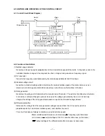
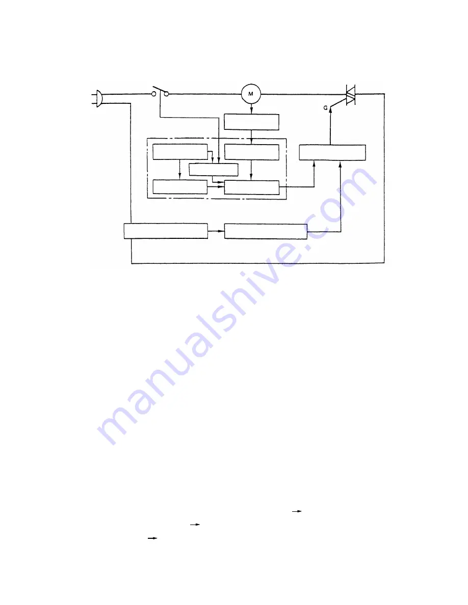
8-1. Control Circuit (Block Diagram)
8-2. Function of Each Block
(1) Rotation speed detector:
Generates a frequency signal proportionate to the actual rotation speed of the motor. A magnetic sensor in the
controller monitors changes in the magnetic flux from a magnet, and generates a frequency signal.
(2) F-V converter:
Converts the frequency signal produced by the rotation speed detector into DC voltage.
(3) Standard voltage circuit:
Generates a standard voltage which determines the no-load rotation speed of the motor and serves as a
reference in maintaining constant rotation speed even when there are fluctuations in the load.
(4) Ramp generator:
Generates the voltage which determines the acceleration of the motor. The soft start function when the motor
is turned on is achieved through a gradual increase of the voltage generated by this circuit. When fully
charged, the voltage of the ramp generator becomes equal to the standard voltage (above).
(5) Differential amplifier:
Compares the voltage from the ramp generator voltages received from the F-V converter (which is
proportionate to the actual motor rotation speed), and amplifies the result.
This circuit functions as follows to maintain a constant rotation speed:
Motor rotation speed decreases (or increases)
frequency signal decreases
(or increases)
output voltage of the F-V converter decreases (or increases)
output voltage of the differential amplifier increases (or decreases).
Rotation speed
detector
Phase control circuit
Load current control circuit
Load current detecting circuit
Ramp generator
Differential
amplifier
Variable resistor
F-V converter
Standard voltage
circuit
Soft start and constant speed control circuit
Triac
Motor
Switch
AC power source
Summary of Contents for SP18VA
Page 21: ......


