--- 8 ---
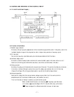
(6) Load current detecting circuit:
Detects the load current by means of a low resistance resistor which is in series with the motor and the triac.
(7) Load current control circuit:
When the detected load is excessive (overload), this circuit sends a command (control signal) to reduce power
to the motor.
(8) Phase control circuit:
Generates the trigger signals necessary to turn the triac on, and delivers them to the gate of the triac. The
conductive angle of the triac is determined by the timing of the generated trigger signals.
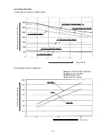
When starting the tool: Controlled by the soft start circuit, the phase control circuit generates trigger signals
to gradually increase the conductive angle of the triac.
Constant speed operation: When there are variations in the rotation speed, the phase control circuit
generates trigger signals to keep the rotation speed as close as possible to the
present rotation speed determined by the standard voltage circuit. In short, when
the load increases and causes the rotation speed to decrease, the conductive
angle of the triac is increases, and the voltage applied to the motor is increased.
In this way, the rotation speed is kept as close as possible to the standard
rotation speed.
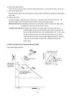
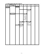
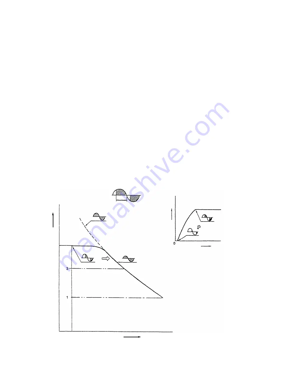
8-3. Motor Characteristics and Voltage Applied to the Motor
Phase control voltage waveform
Conductive
angle
(When electronic control
not applied)
Rotation speed
determined by
the standard
voltage circuit
As the load inceases,
the voltage applied to the
motor increases.
Soft start characteristics
when starting the tool
Voltage applied to
the motor increases
gradually
Switch ON
Time
Rotation speed
Dial
6
Rotation speed
0 No-load
Load
Dial
Dial
Summary of Contents for SP18VA
Page 21: ......


