background image


7 - 72 

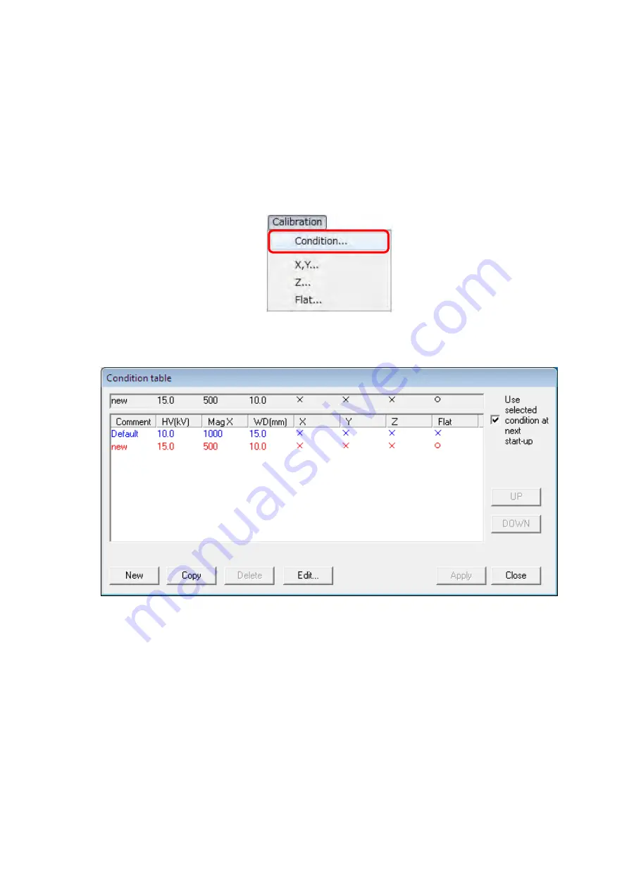
7.23  Setting of Calibration Condition 

 
The new creation and the edit of the calibration condition, and the switch to another 
calibration condition are executed using the Condition table dialog. 
The Condition table dialog is displayed when selecting the [Condition] from the [Calibration] 
menu or clicking the [Condition] block area on the main operation window of 3D-Image 
Viewer. 


Figure 7.23-1  Condition Menu 


Figure 7.23-2    Condition table Dialog 

 
The current condition data is displayed at the top of the window. 
The data that is registered as a default value is displayed at the top of the Condition table 
dialog in blue. Execute the 3D image display with the default value as a basic data when the 
calibration condition is not newly made. The line below from the default value is a calibration 
condition, which are already made. A red character displays the calibration condition applied 
to the display image. The applied calibration condition is displayed in the [Condition] block on 
the main operation window. 
 

Summary of Contents for TM3030 Plus

Page 1: ...structions and precautions carefully Be sure to follow the instructions and warning of instruction manual and warning label Keep this manual in a safe place nearby so it can be referred to whenever needed Copyright C Hitachi High Technologies Corporation 2014 May 2016 5th Edition All rights reserved Printed in Japan Part No 55E 8881 4 HR G HMS ...

Page 2: ...arty in any form or by any means without the express written permission of Hitachi High Technologies Corporation 3 Hitachi High Technologies Corporation assumes no liability for any direct indirect or consequential damages arising from use not described in this manual Utmost care must be exercised when using the instrument 4 This document does not provide any warranty or permission for industrial ...

Page 3: ...computer PC operations and moving the specimen stage Because minors can take unexpected action out of curiosity the system administrator should use utmost caution not to operate the system miners independently or unmentioned way in this manual ABOUT THIS INSTRUCTION MANUAL This Instruction Manual describes TM operating methods maintenance and inspection methods items that are necessary to support ...

Page 4: ...stem provided at the beginning of this Instruction Manual List of Abbreviations Abbreviations that appear frequently in this Instruction Manual and their full spellings are given below PC Personal Computer HV High Voltage DFP Diaphragm Pump TMP Turbo Molecular Pump FOV Field of View ...

Page 5: ...onsumables or parts with a limited warranty period that have failed after the warranty period Geographic Area of Warranty The warranty is limited to within the borders of the country in which the product was purchased Warranty Period The warranty period is one 1 year from the completion date of installation Warranty Limitations and Exclusions HHT does not extend any warranty either implicitly or e...

Page 6: ...d 9 A system failure arising from disassembling or alteration not authorized by HHT 10 A system that has been discarded or sold or relocated without notice to HHT or a system that is bought from a reseller 11 A system failure arising from the use of the system or by an operating method not provided in this Instruction Manual or from a repair performed not under HHT s control 12 A system failure ar...

Page 7: ... service company designated by HHT and request for the performance of a relocation service After Service 1 For any after service requirements please contact the HHT s dealership 2 Any system relocated or sold without contacting in advance the sales department that handles your account or a maintenance service company designated by HHT will be ineligible to receive after service 3 For a period of s...

Page 8: ... relevant laws and directives can conceivable occur in the future when discarding the system either do so by checking relevant laws and regulations or consult the sales department that handles your account or a maintenance service company designated by HHT When discarding a used PC or turning it over for recycling please be sure to erase any data remaining on the hard disk at the customer s respon...

Page 9: ...rnal parts from the instrument or mount any unspecified parts on it 3 Do not modify the instrument for unlocking its safety mechanisms 4 The laws and regulations concerning radiation hazard prevention may be revised or amended as required When using this instrument be sure to check the latest issues of the relevant laws and regulations and take proper safety measures if necessary Handling of Chemi...

Page 10: ...disclaimer and license as libpng 1 0 6 with the following individuals added to the list of Contributing Authors Simon Pierre Cadieux Eric S Raymond Gilles Vollant and with the following additions to the disclaimer There is no warranty against interference with your enjoyment of the library or against infringement There is no warranty that our efforts or the library will fulfill any of your particu...

Page 11: ...nus Holmgren Greg Roelofs Tom Tanner libpng versions 0 5 May 1995 through 0 88 January 1996 are Copyright c 1995 1996 Guy Eric Schalnat Group 42 Inc For the purposes of this copyright and license Contributing Authors is defined as the following set of individuals Andreas Dilger Dave Martindale Guy Eric Schalnat Paul Schmidt Tim Wegner The PNG Reference Library is supplied AS IS The Contributing Au...

Page 12: ...tion The Contributing Authors and Group 42 Inc specifically permit without fee and encourage the use of this source code as a component to supporting the PNG file format in commercial products If you use this source code in a product acknowledgment is not required but would be appreciated A png_get_copyright function is available for convenient use in about boxes and the like printf s png_get_copy...

Page 13: ...ictions 1 The origin of this software must not be misrepresented you must not claim that you wrote the original software If you use this software in a product an acknowledgment in the product documentation would be appreciated but is not required 2 Altered source versions must be plainly marked as such and must not be misrepresented as being the original software 3 This notice may not be removed o...

Page 14: ...e of a hazardous condition that if not avoided can potentially lead to serious property damage damage to the system data damage or environmental pollution without endangering humans NOTE This item is used to provide an explanation to ensure the proper use of the function and the accurate performance of measurements while avoiding minor damage to the system Please comply with all the warning labels...

Page 15: ...tem please contact the Sales Department that handles your account or a maintenance service company designated by HHT The cautionary items and instructions provided on the system or in the Instruction Manual have been developed with a great deal of care Notwithstanding this fact unexpected events can occur When operating the system beyond complying with the instructions it is requested that the cus...

Page 16: ...ilt in laser light source PCs equipped with such laser devices are designed not to emit any laser beam harmful to humans to the outside under normal operating conditions However if the laser beam leaks out of the system and gets into eyes it can cause vision problems Please read the precautions on the laser provided in the Instruction Manual supplied with the PC and in addition be sure to comply w...

Page 17: ...e cover from the system When opening the electron gun and other components for maintenance purposes be sure to turn off the earth leakage breaker and the power switch and unplug the power cord before commencing the work Chapter 5 Maintenance Electric Shock from Improper Grounding When connecting the main unit to the power supply be sure to use the grounded power cable that satisfies law and rule a...

Page 18: ... to an earthquake or other events Do not install the device when delivering and do not transfer the device after installation Our engineer must carry out it Chapter 1 Specifications and Installation Conditions As a rule do not move the diaphragm pump because it is a heavy load of 4 5 kg When moving it by necessity move it carefully after considering the length of piping and cable the safety to one...

Page 19: ...se finger injury when opening and shutting Be sure not to pinch fingers when opening and shutting Chapter 5 Maintenance The finger might get injured in the opening and shutting part of the top cover Be sure not to pinch fingers when opening and shutting Chapter 5 Maintenance Burns from Touching the Filament Assembly and Peripheral Components After the system has been in use the Wehnelt and the ano...

Page 20: ...artment that services your account and request replacement labels Locations of WARNING and CAUTION Labels on the TM3030Plus Main Unit on the Sides Hazardous voltage inside Can cause death or severe injury Do not remove the cover P N 52E 4125 WARNING For Manual Stage For Motor drive Stage Beware of heavy load 68kg Can cause injuries When lifting the heavy load do carefully by two or more persons no...

Page 21: ... death or severe injury Do not remove the cover P N 52E 4125 WARNING Hazardous voltage inside Can cause death or severe injury Do not remove the cover P N 52E 4125 WARNING Hazardous voltage inside Can cause death or severe injury Do not remove the cover P N 52E 4125 WARNING Hazardous voltage 15kV inside Cancausedeathorsevereinjury Do not resolve the electron gun P N 52E 6731 WARNING Beware of high...

Page 22: ...out the Cable Connection To prevent a system malfunction when connecting the power cable or a dedicated cable be sure to turn off the earth leakage breaker and the power switch In particular when plugging or unplugging a USB cable do so by turning off the PC Remember that performing a Safe removal of hardware step on the PC and receiving a USB device can now be removed safely message does not mean...

Page 23: ...son As a rule the customer is not allowed to relocate the instrument Any malfunction might occur in TMP if excessive shock is applied to the instrument without TMP secured 4 Handling of installation table Do not apply excessive vibration or external shock to the table where the instrument is placed Be careful not to apply any vibration to the table especially when doing some work on it About Power...

Page 24: ...e PC On Data Backup In some cases a PC failure or malfunction can cause data corruption To avoid such a problem periodically copy the contents of the hard disk to another hard disk CD ROM a magneto optical disk or other external storage devices Such periodic copying is referred to as a backup For further details on this topic see the instruction manual supplied with the PC About Application Softwa...

Page 25: ...te virus definitions When connecting to the network HHT recommends the establishment of a firewall as an anti computer virus measure between the system and the network Setting up a firewall is a customer responsibility HHT does not warrant that all computer viruses can be prevented by setting up a firewall If there are concerns about a computer virus infection check your system by using anti virus...

Page 26: ...r For these services contact either the sales department handling your account or the Service Department 2 When connecting the PC to a network be sure to take adequate anti computer virus measures For details see the About the computer virus section in this chapter 3 The system is not supplied with an Ethernet cable an appropriate cable should be procured 4 Any change in settings for network conne...

Page 27: ...s the mouse and the keyboard won t work for some reason on the keyboard press the Ctrl Alt and Delete keys simultaneously and shut down the system by following the instructions that appear in the dialog box software resetting After that close Windows normally turn off the main unit and restart it If this condition occurs any data up to that point will be lost If the PC fails to restart after a sof...

Page 28: ...paying attention to the environment around the installation site for the system 1 Avoid installing the system in a place near power lines serving equipment such as a large magnetic clutch and subject to sudden current or magnetic field changes 2 Install the system in a place away from sources of vibration such as large machine tools or transportation facilities roads railroads and the like About M...

Page 29: ...rrespond to the standard of classification of the harmful factor under the laws of Korea 첨부된 아래의 리스트의 화학물질은 산업안전보건법 시행 규칙 별표 11 의 2 제 1 호에 따라 유해인자의 분류기준에 해당하지 않습니다 TableChemical substances for TABLETOP MICROSCOPE TABLETOP MICROSCOPE 용 화학물질 No Part No Product Name 품명 Notes 비고 Attached Presence 첨부 유무 1 539 2132 Vacuum Grease Electron Grease Yes No 유 무 ...

Page 30: ...e or Damage to the System SAFETY 9 NOTICE SAFETY 9 About the Power Supply SAFETY 9 About the Cable Connection SAFETY 9 About the Detector SAFETY 9 About Turbo Molecular Pump SAFETY 10 About Power Outages SAFETY 10 On the Power Supply for the PC SAFETY 11 On Data Backup SAFETY 11 About Application Software SAFETY 11 About the Computer Virus SAFETY 12 About Network Connection SAFETY 13 For the Prope...

Page 31: ...s to be Prepared 1 9 2 INSTALLATION AND SETUP 2 1 2 1 Connecting to the PC 2 1 2 2 Setting up the PC 2 1 2 2 1 Screen Settings 2 1 2 3 Installation of the TM3030Plus Application Program 2 12 2 3 1 Installation of the Application Program 2 15 2 3 2 Installation of the Instruction Manual 2 20 2 3 3 Setup of the System Files 2 25 2 3 4 Confirmation of the Installation 2 27 2 3 5 Installation of the U...

Page 32: ... 2 Loading a Specimen and Adjusting its Height 4 8 4 2 3 Changing Specimens 4 13 4 2 4 Observation Condition Settings 4 18 4 2 5 Signal Select Observation Mode Settings 4 21 4 2 6 Starting Observation 4 25 4 2 7 Searching for Field of View 4 26 4 2 8 Setting a Magnification 4 30 4 2 9 Adjusting the Brightness Contrast 4 32 4 2 10 Coarse Focusing 4 33 4 2 11 Fine Focusing 4 35 4 2 12 Saving the Ima...

Page 33: ...Image Shift Reset Button 4 87 4 3 24 Rotation Button 4 87 4 3 25 Edit Button 4 89 4 3 26 Minimize Button 4 95 4 3 27 Exit Button 4 96 4 3 28 Setting for Save Window 4 97 4 3 29 Save Image Window 4 97 4 3 30 Digital Zoom Window 4 99 4 3 31 Data Entry Measurement Window 4 103 4 3 32 Image Balance Window 4 108 4 3 33 Preset Magnification Window 4 110 4 3 34 Auto B C Adjustment Window 4 111 4 3 35 Con...

Page 34: ...and Uninstalling 7 7 7 5 Environment Required for the Operation of 3D Image Viewer 7 7 7 6 Installing 3D Image Viewer 7 8 7 7 Uninstalling 3D Image Viewer 7 11 7 8 3D Image Viewer Screen Configuration 7 13 7 9 Menu Functions 7 15 7 10 Image Settings View Function 7 23 7 11 Profile Settings View Function 7 28 7 12 Mouse Pointer 7 30 7 13 3D Viewer Functions 7 31 7 14 Operation Procedures 7 33 7 14 ...

Page 35: ...n into TDV Format 7 62 7 20 Print 7 63 7 21 Model Display in Three Dimensions 7 66 7 22 Calibration of 3D Measurement 7 71 7 23 Setting of Calibration Condition 7 72 7 24 Calibration Operations 7 75 7 24 1 Calibration of X Y 7 75 7 24 2 Calibration of Z 7 77 7 24 3 Calibration of Flat 7 79 7 25 Height Calibration Using a 30 degree Tilted Specimen Stub 7 80 7 25 1 Example of Procedure for Flat Cali...

Page 36: ... Correctly measure and set the specimen size and height An incorrect setting can potentially damage the specimen or components inside the specimen chamber CAUTION 5 The turbo molecular pump is a limited life item It should be replaced after five years When the bearings reach the end of their life abnormal heat generation an abnormal noise or abnormal stoppage can occur When replacing the TMP pleas...

Page 37: ...for a long time leave it in an evacuated condition instead of opening the specimen chamber to the atmosphere 6 Notice on Disturbance by Electromagnetic Wave Though this instrument is nothing of the sort which gives off electromagnetic wave intentionally electromagnetic wave is slightly emitted from electronic circuit in this instrument Therefore equipment which is capable of being interfered with ...

Page 38: ...n so as to be magnified and displayed on screen The main feature of this system is observation ability with high magnification which cannot be done with the optical microscope and it permits to get three dimensional images with great focal depth Downsizing the traditional electron microscope and simplifying the operations even beginners who never used electron microscopes are allowed to use this T...

Page 39: ...l microscope 3 Elimination of cumbersome preparation of samples 4 The capacity to mount specimens up to 70 mm across and 50 mm thick 5 PC based operation and the automated focus brightness adjustment function 6 A quick 3 minute starting time 7 Only an indoor power supply is required AC100 to 240 V 5 A or less 8 Able to observe various targets by selecting observation mode and condition ...

Page 40: ... PC and other recording media 13 Recording pixels 1280 960 pixels max 640 480 pixels 14 Data display Micron marker file No date comments 15 Automated function Auto brightness control auto focusing adjustment 16 Auxiliary operation function Raster rotation Magnification preset 2 steps 17 Vacuum pump Compact turbo molecular pump 30 l s Diaphragm pump 1 m3 h 18 Vacuum detector Pirani gauge 19 Frequen...

Page 41: ...ors Display 15 inch screen Interface connector USB2 0 3 0 PC card slots IEEE 1394 6 pin or Oxford EDX is indispensable File device HDD DVD ROM drive installed NOTE A PC display resolution of 1366 768 pixels or less may cause the application to fail to start The use of a high resolution monitor such as SXGA 1280 1024 pixels SXGA 1400 1050 pixels etc may render the size of observation images smaller...

Page 42: ...requency 7 Hz 4 0 µm p p or less 7 Hz frequency 10 Hz 1 5 µm p p or less 10 Hz frequency 2 0 cm s2 or less Magnetic field Meet the following stray magnetic field value for the installation site The allowable value of AC magnetic field is defined as the amount of image distortion elongation shrinkage or bending is 0 5 mm or less in photography at a specified magnification or specified focus positio...

Page 43: ...ifferent from that in other modes so the amplitude of the image may become large WARNING Using the system at a humid or dusty place can result in electric shock or fires For installation prevent a place close to a sink or a humidifier a humid basement room and a dusty or smoky place WARNING When connecting the main unit to the power supply be sure to use the grounded power cable that satisfies law...

Page 44: ... the system in an unstable place or a place liable to fall or toppling due to an earthquake or other events Install the system as it has a space of not less than 200 mm on the left side so that the center of the gravity of the system is positioned near the center of the table Do not install the device when delivering and do not transfer the device after installation Our engineer must carry it out ...

Page 45: ...e 1000 W 800 D 700 H mm Withstand load 100 kg or more The Chair is not included in the size Dimensions is reference Grounded power cable 1200 800 330 606 Manual Stage 633 Motor Drive Stage Diaphragm pump 145 256 Power supply grounding Units mm Recommended Table layout Notebook PC power cable 2 5 m USB cable 200 374 PC Main unit 250 ...

Page 46: ...efer to 1 4 Recommended PC Specifications Table Recommended table Size 1 200 mm W 800 mm D 700mm H or larger Withstand load not less than 100 kg Others Flat No casters Others Ethyl alcohol Metal polishing agent Recommended supplier Ted Pella http www tedpella com material_html polish htm pikal Part name PIKAL paste Ultrasonic cleaning system Blower ...

Page 47: ...e power cable of the main unit in a customer provided outlet 2 2 Setting up the PC 2 2 1 Screen Settings NOTE The setup process and the reference screen images described in this chapter are designed for the PC belonging to the TM3030Plus main unit Unspecified PCs may require a different way for setup and show different screen images from those of this chapter In such a case follow your PC s instru...

Page 48: ...2 2 Figure 2 2 1 1 Start Button Window 2 Select Small icons from View by pull down menu of Control Panel Figure 2 2 1 2 Adjust your computer s settings Window Click Click ...

Page 49: ...appears Click the Personalization icon Figure 2 2 1 3 Adjust your computer s settings Window 4 Scroll down and click the Windows 7 Basic icon Figure 2 2 1 4 Change the visuals and sounds on your computer Window Scroll down Click ...

Page 50: ...tion program is recommended to be used with the setting mentioned above With using the Windows Aero function observation screen imaging speed may be reduced and it may prevent normal observation 6 The following window appears Click the Screen saver icon located in the lower right of the screen and click the Change power settings located in the lower left of the Screen Saver Settings window Figure ...

Page 51: ...igh performance menu is displayed Select Never in the Dim the display Turn off the display and Put the computer to sleep items Then click the Save changes button Figure 2 2 1 8 Change settings for the plan High performance Window NOTE Configure the same above setting in the Balanced and Power saver modes After all the setting is done set Select a power plan to High performance Click Back to Figure...

Page 52: ...rs Change the setting of On battery and Plugged in for When I press the power button to Shut down Change the setting of On battery and Plugged in for When I close the lid to Do nothing Then click the Save changes button Figure 2 2 1 10 Define power buttons and turn on password protection Window Click Click Change to Shut down Change to Do nothing ...

Page 53: ... Windows and application may not work normally or image data may be lost during capturing When this communication error occurred restart the application 11 Return to the Select a power plan window and click Personalization and then Display in the lower left of the window Figure 2 2 1 11 Select a power plan Window Figure 2 2 1 12 Change the visuals and sounds on your computer Window Click Click ...

Page 54: ...ow 13 Confirm the setting is same as bellow 9 point Segoe UI at 96 pixels per inch Scale to this percentage of normal size 100 and click the OK button Figure 2 2 1 14 Custom DPI Setting Window 14 Back to the Display window and click the Adjust resolution Figure 2 2 1 15 Make it easier to read what s on your screen Window Click Click ...

Page 55: ...ged PC Orientation Landscape Figure 2 2 1 16 Change the appearance of your display Window In the case of using English as a Display language for TM3030Plus application please operate the settings below 16 Click Control Panel from the Start button in the left of the desktop window 17 The following window appears Click Region and Language ...

Page 56: ...elect Administrative tab and click Change system locale button in the Language for non Unicode programs Figure 2 2 1 18 Region and Language Window 19 The Region and Language Settings window appears From the pull down list of Current system locale select English United States and click the OK button Click ...

Page 57: ...The following window appears Click the Restart now button Figure 2 2 1 20 Change System Locale Window 21 After restarting open the Administrative tab in the Region and Language window and confirm that the Language for non Unicode programs is English United State ...

Page 58: ...0Plus application program refer to 2 3 1 Installation of the Application Program 2 3 Installation of the TM3030Plus Application Program NOTE When installing the application follow these precautions 1 Log in as TM3030PlusUSER 2 Do not connect the main unit to the PC with USB cable before completion of the installation Figure 2 3 1 Prohibition of the Connecting Main Unit to the PC Main unit USB cabl...

Page 59: ...030PlusUSER If no other user login name is set additionally the login window does not appear 2 Insert the TM3030Plus setup CD ROM into the CD DVD drive 3 The following window appears Click the Run SETUP exe icon Figure 2 3 2 AutoPlay Window ...

Page 60: ...igure 2 3 3 User Account Control Window 5 The following window appears Input Serial Number of the TM3030Plus in the dialog box and click the OK button Serial Number is listed on the product nameplate located on the back of the main unit Figure 2 3 4 Input Serial Number Dialog Box Figure 2 3 5 Product Nameplate Click ...

Page 61: ... appears Click the Installation for TM3030Plus application button Figure 2 3 1 1 TM3030Plus Setup Tools Window Main Menu 2 The following window appears Click the Installation of application program button Figure 2 3 1 2 TM3030Plus Setup Tools Window Installation Click Click ...

Page 62: ...plication failure occurs and so the application is to be repaired refer to 2 5 1 2 Repairing Figure 2 3 1 3 Message Window 3 The following window appears Select English United States and click the OK button Figure 2 3 1 4 Choose Setup Language Window 4 The following window appears Wait until the preparing finishes Figure 2 3 1 5 Preparing to Install Window ...

Page 63: ...ved before will be displayed by default In this case they can be used without changed Click the Next button Figure 2 3 1 7 Customer Information Window NOTE For using with all login user select Anyone who uses this computer all users as Install this application for When selecting Only for me TM3030PlusUSER only the user who is now installing the application can use it Click Click ...

Page 64: ...tall button Figure 2 3 1 8 Ready to Install the Program Window 8 The following window appears and the application program starts to be installed Do not click the Cancel button during this installation Figure 2 3 1 9 Installing TM3030Plus Window Click ...

Page 65: ...ll button Figure 2 3 1 10 Windows Security Window 10 The following window appears Click the OK button Figure 2 3 1 11 Attach Your Device Window 11 When the install process is completed the following window appears Click the Finish button Figure 2 3 1 12 InstallShield Wizard Completion Window Click Click ...

Page 66: ...llation for TM3030Plus application button Figure 2 3 2 1 TM3030Plus Setup Tools Window Main Menu 2 Install the instruction manual Select Installation of the instruction manuals from the Installation menu of the TM3030Plus Setup Tools Figure 2 3 2 2 TM3030Plus Setup Tools Window Installation Click ...

Page 67: ...he Instruction Manual re install it For the details of the uninstall process refer to 2 4 2 Uninstallation of the Instruction Manual Figure 2 3 2 3 Message Window 3 The following window appears Click the OK button Figure 2 3 2 4 Choose Setup Language Window 4 The following window appears Wait until the preparing finishes Figure 2 3 2 5 Preparing to Install Window ...

Page 68: ... window appears Click the Next button Figure 2 3 2 7 Customer Information Window NOTE For using with all login user select Anyone who uses this computer all users as Install this application for When selecting Only for me TM3030PlusUSER only the user who is now installing the application can use it Click Click ...

Page 69: ... Click the Install button Figure 2 3 2 8 Ready to Install the Program Window 8 The instruction manual starts to be installed Do not click the Cancel button during this installation Figure 2 3 2 9 Installing TM3030Plus Manual Window Click ...

Page 70: ...2 24 9 When the install process is completed the following window appears Click the Finish button Figure 2 3 2 10 InstallShield Wizard Completion Window Click ...

Page 71: ...e Installation for TM3030Plus application button Figure 2 3 3 1 TM3030Plus Setup Tools Window Main Menu 2 Setup the System Files Select Setup of system files from the Installation menu of the TM3030Plus Setup Tools Figure 2 3 3 2 TM3030Plus Setup Tools Window Installation Click ...

Page 72: ... 3 3 System Installed Window 4 Click the Exit button in the TM3030Plus Setup Tools window Figure 2 3 3 4 TM3030Plus Setup Tools Window Installation 5 Take out the setup CD ROM from the CD DVD drive NOTE Keep the TM3030Plus setup CD ROM at hand because factory default system data is saved in it Click ...

Page 73: ...esktop Figure 2 3 4 1 TM3030Plus Shortcut Icon 2 Confirm the TM3030Plus is added in the program menu of the Start button Figure 2 3 4 2 Confirmation of Installation 3 Substantial application file is installed in the C Program Files x86 TM3030Plus folder Do not edit move or delete the installed file ...

Page 74: ...ort Figure 2 3 5 1 Connecting the Main Unit and the PC 2 Turn on the main unit The Plug and Play function recognizes the USB device and displays the following message for a few seconds in the lower part of the screen Figure 2 3 5 2 Installing device driver software Message 3 After the USB device driver is installed successfully the following message appears Figure 2 3 5 3 SemUsb Device Message PC ...

Page 75: ... 1 Open Device Manager from Control Panel of the Start menu Figure 2 3 6 1 Device Manager Icon When Device Manager does not appear select Small icons from View by pull down menu of Control Panel Figure 2 3 6 2 Control Panel Figure 2 3 6 3 Control Panel ...

Page 76: ... Device Manager appears Confirm SEM USB Device exists in Universal Serial Bus controllers If it doesn t exist install the USB driver software again Figure 2 3 6 4 Device Manager Window 3 Close Device Manager ...

Page 77: ...oesn t start when the main unit is shut down or the USB cable is unplugged When initializing this message appears 3 Do not shut down the main unit or unplug the USB cable while the application is running 1 Double click the TM3030Plus shortcut icon on desktop to power up the main unit Figure 2 3 7 1 Connecting the Main Unit to the PC 2 The application starts up Figure 2 3 7 2 Application Startup Wi...

Page 78: ... Up Window 4 The Set up the observation screen size when the application has started message appears Click the OK button Figure 2 3 7 4 Observation Screen Size Setup Window 5 The message No User Setting File found Do you default to start up PC message Click the OK button Figure 2 3 7 5 Default to Start Up Window NOTE When initializing do not shut down the main unit or unplug the USB cable Click Cl...

Page 79: ...en the application starts normally the operation window appears Figure 2 3 7 6 Operation Window 7 Select Observation Screen Size from the Maintenance menu in the operation window Figure 2 3 7 7 Maintenance Menu ...

Page 80: ... 8 Observation Screen Size Window 9 Measure the red line appearing in the operation window with a ruler Figure 2 3 7 9 Measuring the Observation Screen Size NOTE Measure the red line in 0 5 mm increments Otherwise a wrong value may input and magnification of the observation screen may not be accurate ...

Page 81: ...environment Figure 2 3 7 10 Observation Screen Size Window 11 Click the Close button to close the Observation Screen Size window 12 Click the X button at the right side of the title bar in the operation window or select Exit from the File menu to close the application program 13 The following window appears Click the OK button to close the application program Figure 2 3 7 11 Application Closing Wi...

Page 82: ...the desktop Figure 2 3 8 1 TM3030Plus Shortcut Icon NOTE Before launching an application check the following items 1 Make sure the PC is connected to the main unit with a USB cable 2 Start the application when the main unit is powered on The application cannot be started if the main unit is turned off or the USB cable is unplugged an initialization message will be displayed 3 When the application ...

Page 83: ...ndow 5 When the application program starts normally the following operation window appears For a description of image observation operations see Chapter 4 Figure 2 3 8 4 Operation Window 6 Select either the X button at the right edge of the title bar in the Operation window or Exit from the File menu to close the application program Click ...

Page 84: ...2 38 7 The following confirmation window appears Click the OK button to close the application program Figure 2 3 8 5 Close the Application Window Click ...

Page 85: ... program with a user name of TM3030PlusUSER 1 Open Control Panel from the Start menu 2 Select Programs and Features from the Control Panel Figure 2 4 1 1 Programs and Features Icon 3 The following window appears Select TM3030Plus and click Uninstall Figure 2 4 1 2 Uninstall or change a program Window 4 The following window appears Click the Yes button ...

Page 86: ...s Wait a moment Figure 2 4 1 4 Windows Installer Window 6 When the following window appears click the Yes button Figure 2 4 1 5 User Account Control Window 7 The following window appears and the uninstallation starts Figure 2 4 1 6 Windows configures TM3030Plus Window Click Click ...

Page 87: ...2 41 8 After finishing the uninstallation confirm the TM3030Plus is removed from the Programs and Features window 9 Close the Programs and Features window ...

Page 88: ...el from the Start menu 2 Select Programs and Features from Control Panel Figure 2 4 2 1 Programs and Features Icon 3 The following window appears Select TM3030Plus Manual and click Uninstall Figure 2 4 2 2 Uninstall or change a program Window 4 The following window appears Click the Yes button Figure 2 4 2 3 Programs and Features Window Click ...

Page 89: ...er Window 6 When the following window appears click the Yes button Figure 2 4 2 5 User Account Control Window 7 After the uninstallation process is finished confirm the TM3030Plus Manual is removed from the Programs and Features window 8 Close the Programs and Features window Click ...

Page 90: ...case where the conventional TM3030Plus application program is already installed and later version needs to be installed apply the following process NOTE Confirm the version of the TM3030Plus application program by seeing the Upgrade for TM3030Plus application in the TM3030Plus Setup Tools The now installing version is shown in the Version Information of the Help menu 1a Power up the PC and login a...

Page 91: ...g window appears Click Run SETUP exe Figure 2 5 1 1 AutoPlay Window 1d Easy install tool starts automatically If the User Account Control window appears click the Yes button Figure 2 5 1 2 User Account Control Window Click ...

Page 92: ...l Number is listed on the product nameplate on the back of the main unit Figure 2 5 1 3 Input Serial Number Dialog Box Figure 2 5 1 4 Product Nameplate 1f The following window appears Click the Upgrade for TM3030Plus application button Figure 2 5 1 5 TM3030Plus Setup Tools Window Main Menu Serial No Click ...

Page 93: ...ation program button Figure 2 5 1 6 TM3030Plus Setup Tools Window Upgrade 1h The following window appears Click the OK button Figure 2 5 1 7 Choose Setup Language Window 1i The following window appears Click the Yes button Figure 2 5 1 8 Continue Setup Window Click ...

Page 94: ...llowing window appears Wait until the preparation finishes Figure 2 5 1 9 Preparing to Install Window 1k The following window appears Click the Next button Figure 2 5 1 10 Resuming the InstallShield Wizard Window Click ...

Page 95: ...llowing window appears click the OK button Figure 2 5 1 12 User Account Control Window NOTE When the TM3030Plus application program Setup exe is installed with the TM3030Plus Setup tools the User Account Control window does not appear because the change of the setting has been permitted on the User Account Control window upon the startup of the TM3030Plus Setup tools ...

Page 96: ...ppears Click the OK button Figure 2 5 1 13 Attach Your Device Window 1o When the installation is completed successfully the following window appears Click the Finish button Figure 2 5 1 14 InstallShield Wizard Completed Window Click ...

Page 97: ...he application program NOTE Confirm the version of the TM3030Plus application program by seeing the Upgrade for TM3030Plus application in the TM3030Plus Setup Tools The now installing version is shown in the Version Information of the Help menu 2a Click the Upgrade for TM3030Plus application button of the following TM3030Plus Setup Tools main menu Figure 2 5 1 15 TM3030Plus Setup Tools Window Main...

Page 98: ...g window appears Click the Upgrade of application program button Figure 2 5 1 16 TM3030Plus Setup Tools Window Upgrade 2c The following window appears Click the OK button Figure 2 5 1 17 Choose Setup Language Window Click ...

Page 99: ...wing window appears Wait until the preparation finishes Figure 2 5 1 18 Preparing to Install Window 2e The following window appears Click the Next button Figure 2 5 1 19 Welcome to the InstallShield Wizard Window Click ...

Page 100: ...dow appears Select the Repair button and click the Next button Figure 2 5 1 20 Program Maintenance Window 2g The following window appears Click the Install button Figure 2 5 1 21 Ready to Install the Program Window Click Click ...

Page 101: ... 2 5 1 22 User Account Control Window 2i The following window appears Do not click the Cancel button during this installation Figure 2 5 1 23 Installing TM3030Plus Window 2j The following window appears Click the OK button Figure 2 5 1 24 Attach Your Device Window Click ...

Page 102: ...2 56 2k When the installation is completed successfully the following window appears Click the Finish button Figure 2 5 1 25 InstallShield Wizard Completion Window Click ...

Page 103: ...sion needs to be installed apply the following process 1a Select Upgrade for TM3030Plus application from the following TM3030Plus Setup Tools main menu Figure 2 5 2 1 TM3030Plus Setup Tools Window Main Menu 1b The following window appears Click the Upgrade of the instruction manuals button Figure 2 5 2 2 TM3030Plus Setup Tools Window Upgrade Click Click ...

Page 104: ... and click the OK button Figure 2 5 2 3 Choose Setup Language Window 1d The following window appears Click the Yes button Figure 2 5 2 4 Setup Continue Window 1e The following window appears Wait until the preparing finishes Figure 2 5 2 5 Preparing to Install Window ...

Page 105: ...ars Click the Next button Figure 2 5 2 6 Welcome to the InstallShield Wizard Window 1g The following window appears Do not click the Cancel button during this installation Figure 2 5 2 7 Installing TM3030Plus Manual Window Click Click ...

Page 106: ...ol Window NOTE When the TM3030Plus application program Setup exe is installed with the TM3030Plus Setup Tools the User Account Control window does not appear because the change of the setting has been permitted on the User Account Control window upon the startup of the TM3030Plus Setup Tools Click ...

Page 107: ...gure 2 5 2 9 InstallShield Wizard Completed Window 2 Repairing Use this function when installing the instruction manual of the same version as already installed 2a The following window appears Choose English United States and click the OK button Figure 2 5 2 10 Choose Setup Language Window Click ...

Page 108: ...owing window appears Wait until the preparing finishes Figure 2 5 2 11 Preparing to Install Window 2c The following window appears Click the Next button Figure 2 5 2 12 Welcome to the InstallShield Wizard Window Click ...

Page 109: ...dow appears Select the Repair button and click the Next button Figure 2 5 2 13 Program Maintenance Window 2e The following window appears Click the Install button Figure 2 5 2 14 Ready to Install the Program Window Click Click ...

Page 110: ...g window appears The instruction manual starts to be installed Figure 2 5 2 15 Installing TM3030Plus Manual Window 2g When the following window appears click the Yes button Figure 2 5 2 16 User Account Control Window Click ...

Page 111: ...2 65 2h When the installation finished the following window appears Click the Finish button Figure 2 5 2 17 InstallShield Wizard Completion Window Click ...

Page 112: ...lems related to functions can occur 4 Do not eject the TM3030Plus setup CD ROM from the optical drive when using it There is a possibility that the program is not installed normally Load the setup CD ROM on the optical drive The following TM3030Plus Setup Tools menu will start automatically Figure 2 6 TM3030Plus Setup Tools Window Functions of the TM3030Plus setup CD ROM TM3030Plus Setup Tools are...

Page 113: ...the already installed application first and then the installation becomes enabled For the installation procedures refer to 2 3 Installation of the TM3030Plus Application Program For the uninstallation procedures refer to 2 4 Uninstallation of the TM3030Plus Application Program 2 Installation of instruction manual The TM3030Plus instruction manual can be installed If already installed it cannot be ...

Page 114: ...work properly and some troubles may occur 2 6 2 Upgrading the Application Select Upgrade for TM3030Plus application to show the following TM3030Plus Setup Tools window Upgrade Figure 2 6 2 TM3030Plus Setup Tools Window Upgrade Use this function for upgrading the TM3030Plus application program and Instruction manual which are already installed Downgrading is not possible 1 Backup of system files Ba...

Page 115: ...pgrading of the Instruction Manual 4 Recover the system files Restore the back up system file from TM3030Plus_Backup folder on desktop Without installation of the system file TM3030Plus application program does not start Do not use the back up system file for other systems Otherwise the system does not work properly and some troubles may occur 2 6 3 Output Log Data Select Output log data from the ...

Page 116: ...em Configuration Figure 3 1 shows the external view of the TM3030Plus Tabletop Microscope Figure 3 1 External View of the TM3030Plus Tabletop Microscope Diaphragm pump Main unit PC supplied by the customer Table supplied by the customer ...

Page 117: ...and signal cables diaphragm pump Evacuation indicator detail Evacuation indicator EVAC AIR switch Specimen stage X Y stage knob Top cover Specimen stage Pull out handle SYSTEM LED Green Turns ON when the system is normal Does not light when the error occurs AIR LED Yellow Lights ON when the specimen chamber is at atmospheric pressure and blinks On and OFF during air introduction EVAC LED Blue Ligh...

Page 118: ...ure 3 2 1 3 Main Unit Right Side View Figure 3 2 1 4 shows the electron gun section under the top cover Figure 3 2 1 4 Electron Gun Section Power switch Electron gun Axis adjustment knobs Electron gun cushion ...

Page 119: ...3 4 3 2 2 Diaphragm Pump Figure 3 2 2 shows the diaphragm pump Figure 3 2 2 Diaphragm Pump Evacuation tube connector Signal connector Power connector ...

Page 120: ...s 1a Mouse cursor Corresponding to mouse operation an arrow on the screen a hand shaped mark or a micro adjustment mark moves 1b Click Pressing a left mouse button and immediately releasing it In this instruction manual long holding it down without moving a mouse is also referred to as click 1c Double click Clicking a left mouse button twice in quick succession 1d Drag Moving a mouse while holding...

Page 121: ...vation 2 Title bar Displays the name of an application 3 Menu bar Provides access to the functions of the application Select your target function 4 View mode settings area 15 Signal select observation mode settings area 1 Start stop button 6 Title bar button 5 Image save buttons 7 Image observation area 2 Title bar 3 Menu bar 12 Rotation button 13 Image shift reset button 11 Focus settings area 10...

Page 122: ...tion image 9 Magnification settings area Specifies an observation magnification 10 Brightness contrast settings area Specifies brightness and contrast of an observation image 11 Focus settings area Adjusts focus of an observation image 12 Rotation button Rotates an observation image in any direction 13 Image shift reset button Resets the settings of an image shift see 4 2 7 1b 14 Observation condi...

Page 123: ...Condition Settings 1 4 2 5 Signal Select Observation Mode Settings 2 4 2 6 Starting Observation 4 2 7 Searching for Field of View 4 2 8 Setting a Magnification 4 2 9 Adjusting the Brightness Contrast 4 2 11 Fine Focusing 4 2 12 Saving the Image Data 4 2 13 Checking the Image Data 4 2 15 Shutting Down the System 4 2 14 Terminating the Image Observation 4 2 10 Coarse Focusing 1 The application start...

Page 124: ... 1 2 Starting the System Power Switch Operation 3 The LED lamp located in the lower right side of the main unit indicates the pressure condition of the system The LED display changes depending on the EVAC AIR switch operation 3a AIR LED lights yellow Introduction of air into the specimen chamber has been completed Ready for exchanging specimen 3b AIR LED blinks yellow Air is in the process of bein...

Page 125: ...en chamber Figure 4 2 1 4 EVAC LED Blue Lighting 4 Check the lighting pattern of the EVAC LED blue If it is blinking wait until it starts lighting Depending on the EVAC AIR switch operation AIR LED might light or blink yellow In this case push the EVAC AIR switch to evacuate the specimen chamber After completing evacuation the lighting pattern of EVAC LED will change from blinking to lighting AIR ...

Page 126: ...6 Turn on the PC 7 Start the application 7a Choose one from the followings to start the application Double click the TM3030Plus shortcut icon on the desktop screen Select TM3030Plus from the start menu Right click the shortcut icon and select Open Figure 4 2 1 6 Starting Application Double click or right click and select Open Select ...

Page 127: ... the following items 1a Specimens that can Blow Up When Placed in a Vacuum An object filled with gas or liquid such as a balloon can blow up when placed in a vacuum to damage internal components These specimens can be observed by breaking the outer surface in advance Examples Balloons inflated and sealed eggs of any size or type cherry tomatoes citrus fruits and living things such as insects and f...

Page 128: ... can stick to the objective lens They can also adversely affect the imaging due to magnetic deflection of an electron beam Such samples can be observed by completely demagnetizing them Examples Magnets and magnetic recording media etc 1f Other Examples Substances harmful to human bodies and environment unfixed samples and living things should not be observed NOTE Because the specimen chamber is ev...

Page 129: ...items use glue or woodwork bond in small amounts Set them in the specimen chamber after they have become thoroughly dry 4 Fix the specimen on the conducting double sided tape Figure 4 2 2 3 Fixing the Specimen on the Specimen Stub NOTE The maximum size of a specimen to be observed is up to 70 mm in diameter In any case do not mount a specimen exceeding the specified size or the specimen can contac...

Page 130: ...1 mm 0 5 to 1 5 mm As shown in Figure 4 2 2 7 loosen the lock nut 1 and turn the height adjustment screw to adjust the height Then tighten the lock nut 1onto the lock nut 2 to secure the specimen stub In addition rotate the lock nut 2 once on the specimen height gauge to confirm any part of the specimen surface does not contact the gauge There are two pieces of the height adjustment screw Choose e...

Page 131: ...4 12 Figure 4 2 2 6 Specimen Height Gauge and Specimen Stub Assembly Figure 4 2 2 7 Adjusting the Specimen Height Approx 1 mm Reference position 0 5 1 5 mm lock nut 1 Height adjustment screw lock nut 2 ...

Page 132: ...is completed 2 When air introduction is completed AIR LED lights yellow from a blinking state 3 Wait a few seconds after AIR LED lights yellow Then grip the handle to draw out the specimen stage and remove the specimen stub assembly Figure 4 2 3 1 EVAC AIR Switch Operation Introducing Air Figure 4 2 3 2 Pulling Out the Specimen Stage NOTE Do not draw out the specimen stage forcibly by the time the...

Page 133: ...tub assembly with its height already adjusted securely into the holder base of the stage until it stops Figure 4 2 3 4 Attaching the Specimen Stub Assembly Figure 4 2 3 5 Hexagon Socket Head Screw for Fixing Specimen Stub Assembly Specimen stub assembly Hexagon socket head screw Stage Specimen stub assembly ...

Page 134: ...tub assembly In that case use the ball wrench 2 so that it does not touch the stage feeding screw When removing the specimen stub assembly loosen the hexagon socket head screw first and remove it Do not use the ball wrench other than the provided ball wrench 2 NOTICE When bringing your hands close to the motion mechanism of the specimen stage during specimen change Be careful not to touch any movi...

Page 135: ...if the specimen does not contact the surrounding components of the specimen chamber as shown below Figure 4 2 3 8 Specimen Change CAUTION The specimen stage weighs approximately 5 kg When exchanging specimens securely grasp the handle and be careful not to get your hands pinched NOTE As shown in Figure 4 2 3 9 if the specimen or the specimen stub touches the upper face of the frontage re adjust th...

Page 136: ...ile gently holding the specimen stage press the EVAC AIR switch to conduct evacuation When the evacuation process is finished the lighting pattern of EVAC LED blue switches from blinking to lighting Figure 4 2 3 10 EVAC AIR Switching Operation Evacuation ...

Page 137: ...set using the observation condition selection buttons The current condition is indicated by a green border If the observation condition is switched during observation Auto B C adjustment is executed Select a desired condition depending on the specimen to be observed the observation purpose and the magnification settings The observation condition previously selected will be applied upon the applica...

Page 138: ...ification is only reference value Set the advanced value depending on samples and purpose When Low mag is selected the l mark is displayed in the information area located in the lower right part of the image observation area see 4 3 2 Figure 4 2 4 2 Observation Condition Settings 5 kV Low Mag 1b Middle mag An electron beam is focused more than Low mag achieving relatively high resolution However i...

Page 139: ...erence value Set the advanced value depending on samples and purpose When High mag is selected the h mark is displayed in the information area located in the lower right part of the image observation area see 4 3 2 Figure 4 2 4 4 Observation Condition Settings 5 kV High Mag The features of the observation condition of 5kV are explained below Low Mag Middle Mag High Mag Electron beam focusing Coars...

Page 140: ... 2 5 Signal Select Observation Mode Settings The image signals BSE SE Mix and the observation modes Conductor Standard Chg up Red can be set using the signal select observation mode selection buttons The current image signal is indicated by a green border If the Signal Select Observation mode is switched during observation Auto B C adjustment is executed The observation mode is switched every time...

Page 141: ... the information area located in the lower right part of the image observation area see 4 3 2 when Shadow 1 or Shadow 2 is selected the S mark is displayed when TOPO is selected the T mark is displayed Every time the BSE button is clicked Conductor Standard or Chg up Red is selected in order and the selected observation mode is displayed under the BSE button Select a desired mode depending on the ...

Page 142: ...hg up Red is selected the L mark is displayed in the information area located in the lower right part of the image observation area see 4 3 2 Figure 4 2 5 4 Signal Select Observation Mode Settings BSE Chg up Red 2 SE Secondary Electron Topographical information on a sample surface can be obtained Every time the SE button is clicked Standard or Chg up Red is selected in order The current mode will ...

Page 143: ...Figure 4 2 5 6 Signal Select Observation Mode Settings SE Chg up Red 3 Mix BSE and SE signals can be mixed to show a composite image When Mix is selected the M mark is displayed in the information area located in the lower right part of the image observation area even though any image mode BSE i e COMPO Shadow 1 Shadow 2 or TOPO is selected see 4 3 2 3a Standard This observation mode is suitable f...

Page 144: ...ettings Mix Chg up Red NOTE Compared to Conductor the life of the filament can be shorten in Standard and Chg up Red 4 2 6 Starting Observation 1 When EVAC LED lights blue the Start button on the operation window turns to an active state Figure 4 2 6 1 Starting Observation 2 Click the Start button to display an image The sample is irradiated and the auto start function activates the Auto focus and...

Page 145: ...ield of View The way to identify a target field of view depends on the type of the specimen stage manual stage or motor drive stage At the same time it is preferable to set lower magnification e g 100x or lower See 4 2 8 1 Searching for Field of View Manual Stage There are two ways for searching for a target field of view 1a Operating the XY knobs If you want to move the field of view extensively ...

Page 146: ...fore after shifting the field of view be sure to set the rotation angle to 0 for image rotation 1b Image shift When moving the field of view finely at a high magnification of 5 000x or higher the use of image shift is more preferable Image shift is a function to shift a field of view by moving the scanning area of electron beam Place the mouse cursor on a point the red circle in Figure 4 2 7 3 whi...

Page 147: ...rching for FOV Image Shift Operation Figure 4 2 7 4 Searching for FOV Image Shift Operation Click the image shift reset button to recover the previous field of view Figure 4 2 7 5 Searching for FOV Image Shift Reset Operation ...

Page 148: ...ervation screen select 8 Points or 4 Points from the Mouse Control Mode in the Stage menu For the details refer to 4 3 7 2 Mouse Control Mode When matching the mouse cursor to the marks the stage buttons displayed on the observation screen the cursor changes into the mark Under such a condition if the left mouse button is clicked the mouse cursor stays on the mark and the field of view does step m...

Page 149: ...ogether with brightness contrast and focus changed correspondingly In such cases appropriately operate the various auto buttons such as auto B C see 4 2 9 2 auto focusing see 4 2 10 2 and manual focus adjustments see 4 2 11 1 to set conditions to facilitate observation Magnification can be set by any of the following methods 1 Clicking the Magnification Button Figure 4 2 8 1 Magnification Settings...

Page 150: ...the image perform adjustments until an appropriate magnification level is attained Adjustment can be continued until the left mouse button is released even if the cursor moves outside of the Magnification button 3 Clicking the Preset Button Figure 4 2 8 3 Magnification Settings Preset Button Operation By registering magnifications that is frequently used two magnification levels can be memorized y...

Page 151: ...ion of 5 000x or lower 4 2 9 Adjusting the Brightness Contrast Brightness and contrast can be manually or automatically adjusted 1 Manual Operation To adjust the brightness and contrast manually click either or side of the Brightness or Contrast button While pressing the button brightness and contrast continue to change For the details refer to 4 3 18 Brightness Button and 4 3 19 Contrast Button F...

Page 152: ...e search process 4 2 10 Coarse Focusing Manual focusing and auto focusing are available 1 Manual Operation Figure 4 2 10 1 Coarse Adjustment of Focusing Manual Operation To adjust focus click either or side of the Focus button While pressing the button the focus continues to vary If an accurate focus position is not found use auto focusing function see 4 2 10 2 and then check it by performing manu...

Page 153: ... 2 10 4 Coarse Focusing Auto focusing in Progress Screen NOTE The accuracy of Auto focusing can be affected by the specimen surface structures Auto focusing will not operate properly if the specimen surface contains few minute structural features its contrast is low or the specimen gets charged easily In such cases perform manual focusing Focus Focus ...

Page 154: ...he screen Figure 4 2 11 1 Fine Focusing Reduce Button Operation 1b Move the cursor into the image observation area or the Focus button Then the cursor changes to the mark Figure 4 2 11 2 Fine Focusing Mouse Dragging Operation 1c Drag the mouse to the right or left direction and focus correspondingly changes to be fine adjusted While viewing the image perform appropriate focusing Adjustment can be ...

Page 155: ...4 36 Figure 4 2 11 3 Fine Focusing in Observation Area Mouse Dragging Operation Figure 4 2 11 4 Fine Focusing in Focus Button Mouse Dragging Operation ...

Page 156: ...timal point see 4 2 11 1c the image shows blurred concentric circles as in the figure below Figure 4 2 11 5 Image without Astigmatism In the presence of astigmatism the image runs in one direction by moving the focus back and forth see 4 2 11 1c as in the figure below Figure 4 2 11 6 Image Showing Astigmatism If astigmatism is present it can be corrected as described below For ease in correction p...

Page 157: ...ed When changing the focus point the image may run as in Figure 4 2 11 6 In this case the astigmatism is not appropriately corrected Again perform astigmatism correction 4 2 12 Saving the Image Data After adjusting the focus click the Slow button in View mode settings area to show an image equivalent to an actual image to be saved where you can check the detailed structure For changing brightness ...

Page 158: ...on to close the Setting for Save window 2 Click either the Save button see 4 3 15 or the Quick Save button see 4 3 14 to capture images 3 After image capture the Save Image window appears Enter a file name and save the data by selecting the destination of save and the type of file JPEG bitmap or TIFF When not saving the file click the Cancel button During the save processing Freeze is selected in ...

Page 159: ...280x1100 pixels 100 400 KB Table 4 2 12 2 Image Save Type and Image Save Size bmp Image Save Type Quick Save size Save size Images only 640x480 pixels 301 KB 1280x960 pixels 1 202 KB Image information 640x520 pixels 327 KB 1280x1040 pixels 1 302 KB Image info comments 640x550 pixels 345 KB 1280x1100 pixels 1 377 KB Table 4 2 12 3 Image Save Type and Image Save Size tif Image Save Type Quick Save s...

Page 160: ...image was saved last Figure 4 2 13 Image Data Save Folder NOTE If reduced images are not displayed in the folder click the View button on the Toolbar and select either Medium Icons or Large Icons This displays a list of saved images in the folder 4 2 14 Terminating the Image Observation 1 Click the Stop button to terminate the image observation process Figure 4 2 14 1 Terminating the Image Observa...

Page 161: ...tion NOTE When exchanging specimens and then pressing the EVAC AIR switch for air introduction into the specimen chamber the displayed image on screen will disappear 3 Close the application 3a Click X on the Title bar located in the upper right area of the operation window or select Exit from the File menu 3b A termination confirmation dialog appears Click the OK button to close the application If...

Page 162: ...r and then remove the specimen 2 Press the EVAC AIR switch to evacuate the specimen chamber observation enabled After completion the lighting pattern of EVAC LED blue changes from blinking to lighting Figure 4 2 15 1 Pressing the EVAC AIR Switch Evacuation Operation 3 Close the application and shut down the PC Figure 4 2 15 2 PC Shut Down ...

Page 163: ...t off Figure 4 2 15 3 System Shutting Down NOTE If image observation is not performed for a long time activate the main unit and evacuate air from the specimen chamber at least once every two weeks in order to keep the specimen chamber in a vacuum condition ...

Page 164: ...ervation condition Observation mode Image signal image mode information image number date time distance and magnification as well as comments The information items and comments can be displayed or hidden To set the display condition click the Edit button or select Setting for Save from the File menu For the details on settings refer to 4 3 28 Setting for Save Window Figure 4 3 2 Information Commen...

Page 165: ...enu Figure 4 3 3 1 File Menu 1 Observation Figure 4 3 3 2 File Menu Observation Menu 1a Start HV ON Starts electron beam irradiation and then an image is displayed The same operation is allowed by pressing the Start button on the operation window For the details refer to 4 3 10 Start Stop Button NOTE When the Start stop button shows Stop the Start HV ON is not selectable 1b Stop HV OFF Terminates ...

Page 166: ...ils refer to 4 3 15 Save Button 3 Setting for Save The Setting for Save window appears allowing the display non display settings of the information items comment entry edit and the settings of image save type name When Quick Save or Save is executed the specified conditions are reflected in the created image file The Edit button operation on the operation window allows the same process to be perfo...

Page 167: ...e between two points can be measured on screen Edited images can be saved as image files image save size 640x480 pixels image only 640x520 pixels image information and 640 550 pixels image information comments For the details refer to 4 3 31 Data Entry Measurement Window 3 Digital Zoom A high resolution image is captured and displayed as a digital zoom image When a part to be enlarged is specified...

Page 168: ...ss to be performed For the details refer to 4 3 11 View Mode Selection Button 2 Signal Select Figure 4 3 5 3 View Menu Signal Select Menu Signals can be selected depending on a target image you want to acquire The Signal select observation mode selection button operation on the operation window allows the same process to be performed For the details refer to 4 3 13 Signal Select Observation Mode S...

Page 169: ...er of a sample is relatively larger In the image shown below the brighter part indicates lead Pb while the darker part indicates tin Sn When COMPO is selected any mark is not displayed in the information area located in the lower right part of the image observation area see 4 3 2 Figure 4 3 5 5 Image Mode Settings COMPO 3b Shadow 1 Select Shadow 1 from the Image Mode menu to display an image illum...

Page 170: ...played in the information area located in the lower right part of the image observation area see 4 3 2 Figure 4 3 5 7 Image Mode Settings Shadow 2 3d TOPO Select TOPO from the Image Mode menu This mode is useful when the topographic information is to be exaggerated When TOPO is selected the T mark is displayed in the information area located in the lower right part of the image observation area se...

Page 171: ...alue of D i e the distance from a specimen surface to a BSE detector displayed in the information area becomes larger the contrast of the image becomes weaker In particular if the image mode is Shadow 1 Shadow 2 or TOPO that phenomenon will be remarkable To achieve good contrast pay attention to the specimen height see 4 2 2 6 7 In the case where Distance is selected in the Information block See 4...

Page 172: ...ce on the Auto B C adjustment window See 4 3 34 The Auto B C button operation allows the same process to be performed For the details refer to 4 3 20 Auto B C Button 7 Auto Focus Automatically adjusts the focus appropriately The Auto Focus button operation allows the same process to be performed For the details refer to 4 3 22 Auto Focus Button 8 Image Shift Reset Resets the field of view using a ...

Page 173: ...itivity Displays the Control Sensitivity window See 4 3 35 where control sensitivity of operation buttons the Magnification button and the Brightness button etc can be adjusted 4 Astigmatism Correction Figure 4 3 6 2 Setting Menu Astigmatism Correction Menu 4a Yes Displays the astigmatism correction operation unit in the information comments area on the operation window Use this function if astigm...

Page 174: ...les Chg up Red When observing non conductive samples in the Standard mode brightness contrast can change over time i e brightness change or image can look shifted unexpectedly i e image deviation In such cases it is recommended that the observation mode should be set to Chg up Red 5b Signal select SE Mix Figure 4 3 6 4 Setting Menu Observation Mode Menu When SE or Mix is selected the two observati...

Page 175: ...enu Observation Condition Menu The observation condition can be selected from 5 kV 15 kV and EDX in the Observation Condition menu The Observation condition selection button operation on the operation window allows the same process to be performed For the details refer to 4 3 12 Observation Condition Selection Button 6a 5 kV Well suited for observing fine features on the specimen surface 5 kV can ...

Page 176: ...to 5 2 Beam Axis Alignment 7 Observation Surface Figure 4 3 6 6 Setting Menu Observation Surface Menu 5 kV of the Observation condition can be selected along with Low mag Middle mag or High mag Similarly every time the 5 kV button operation in Observation condition settings area is clicked Low mag Middle mag and High mag can be switched in order For the details refer to 4 3 12 Observation Conditio...

Page 177: ...ted the mark is displayed in the upper left part of the information area located in the lower right part of the image observation area Figure 4 3 6 9 Information Area Display Fine 8c Fine High Contrast Optimizes image automatically to capture the image having less blur sharpened outline and high contrast This is effective for low key condition such as the Chg up Red mode or 5 kV When executing Qui...

Page 178: ...ntrast the effect of Fine and Fine High Contrast might be unclear NOTE Note that even though Fine or Fine High Contrast is selected form Image Optimize the effect is not reflected in an image captured using 3D Image capture 4 3 7 Stage Menu The following menus are displayed when the motor drive stage is installed Figure 4 3 7 1 Stage Menu 1 Stage Position Displays the Stage Position window to show...

Page 179: ... can be selected The value of the specimen stub size box shows the current size 1e Home position button Moves the motor drive stage to the home position NOTE In the following cases the dialog message shown below is displayed until the initialization processing is completed At this time the operation screen cannot be operated In the case where the application has been started but the stage initiali...

Page 180: ...ge Menu Mouse Control Mode Menu 8 Points 2b 4 Points Displays the stage move buttons in four directions top bottom right left Figure 4 3 7 5 Stage Menu Mouse Control Mode Menu 4 Points 2c None Hides the stage move button Figure 4 3 7 6 Stage Menu Mouse Control Mode Menu None NOTE While introducing air into the specimen chamber the stage cannot be operated ...

Page 181: ... Screen Size window that allows saving the size of the image observation area Be sure to set the observation screen size after installing the application on the PC For the details refer to 2 3 7 Setup of the Observation Screen Size NOTE The proper display of scales requires the correct registration of an observation screen size 3 Output Log Data Outputs the operation information of the system to t...

Page 182: ...anation of buttons when the mouse cursor is moved to under the button 3 User Information Displays the user information window that allows storing user information for controlling the application Use this function when it is necessary to keep track of the party that controls the program for operational purposes For the details refer to 4 3 39 User Information Window 4 Version Information Displays t...

Page 183: ...age appears indicating HV ON After it disappears an image is displayed Moreover when clicking the Start button right after the specimen exchange i e evacuation is completed or the application startup the dialog message appears indicating the Auto start in progress condition and Auto focusing and Auto B C are operated along with the magnification set to 100x Once the electron beam irradiation start...

Page 184: ...ndicating a system failure appears after the Auto start in progress window disappears refer to 5 5 Error Messages 2 Stop HV OFF Button Figure 4 3 10 4 Start Stop Button Stop While the Start stop button shows Stop electron beam irradiation is on HV ON Click the Stop button to stop electron beam irradiation Then the button will be switched to Start NOTE A message can appear to show that the conditio...

Page 185: ...w while adjusting the observation position of the specimen 2 Slow Figure 4 3 11 2 View Mode Selection Button Slow Well suited for checking an image with a high image quality An image having an actual image quality to be saved will be displayed 3 Reduce Figure 4 3 11 3 View Mode Selection Button Reduce Well suited for the manual fine adjustment of focus see 4 2 11 1 or astigmatism correction see 4 ...

Page 186: ...the observation condition selection buttons The current condition is indicated by a green border If the observation condition is switched during observation Auto B C adjustment will be executed Select a desired condition depending on the specimen to be observed the observation purpose and the magnification settings The observation condition previously selected will be applied upon the application ...

Page 187: ...ation at a magnification of 2 000x to 6 000x This magnification is only reference value Set the advanced value depending on samples and purpose When Middle mag is selected the m mark is displayed in the information area located in the lower right part of the image observation area see 4 3 2 Figure 4 3 12 3 Observation Condition Settings 5 kV Middle Mag 1c High mag An electron beam is more focused ...

Page 188: ...es suitable for high magnification observation When 15 kV is selected the N mark is displayed in the information area located in the lower right part of the image observation area see 4 3 2 Figure 4 3 12 6 Observation Condition Settings 15 kV 3 EDX This observation condition is well suited for observing specimens that do not produce adequate brightness contrast levels Select EDX for EDX analysis i...

Page 189: ...observation mode previously selected will be applied upon the application startup Figure 4 3 13 1 Signal Select Observation Mode Selection Button NOTE If switching the observation modes Conductor Standard and Chg up Red among different image signals or even in a single image signal it takes over ten seconds to reach the specified degree of vacuum At the same time image brightness changes After the...

Page 190: ...ceramic biological samples or foods When Standard is selected the M mark is displayed in the information area located in the lower right part of the image observation area see 4 3 2 Figure 4 3 13 3 Signal Select Observation Mode Settings BSE Standard 1c Chg up Red When observing non conductive samples in the Standard mode brightness contrast can change over time i e brightness change or image can ...

Page 191: ... area see 4 3 2 Figure 4 3 13 5 Signal Select Observation Mode Settings SE Standard 2b Chg up Red When observing non conductive samples in the Standard mode brightness contrast can change over time i e brightness change or image can look shifted unexpectedly i e image deviation In such cases it is recommended the observation mode should be set to Chg up Red When Chg up Red is selected the L mark i...

Page 192: ...ion In such cases it is recommended that the observation mode should be set to Chg up Red When Chg up Red is selected the L mark is displayed in the information area located in the lower right part of the image observation area see 4 3 2 Figure 4 3 13 8 Signal Select Observation Mode Settings Mix Chg up Red NOTE Compared to Conductor the life of the filament can be shorten in Standard and Chg up R...

Page 193: ...e starts Figure 4 3 14 3 Image Capture Screen The time to image capture depends on the each View mode During the processing a dialog message appears After the completion it will disappear When canceling Quick Save click the Cancel button on the dialog message NOTE When either Fast or Reduce is selected in View mode settings area Quick Save cannot be canceled If Quick Save is executed with Freeze s...

Page 194: ...Window NOTE The items previously selected in the Setting for Save window see Figure 4 3 28 are displayed in the Information comment area see 4 3 2 To modify the condition click the Edit button see 4 3 27 or select Setting for Save from the File menu 4 3 15 Save Button Figure 4 3 15 1 Save Button A high resolution image is captured and saved as an image file Image Save size 1280x960 pixels image on...

Page 195: ... be captured Figure 4 3 15 3 Image Data Capture Screen It takes about 30 to 40 seconds to capture an image At the same time the dialog appears indicating the progress of the image capture process It will disappear when image capture is finished To cancel the image capture click the Cancel button NOTE To avoid noise in the saved image be careful not to vibrate the system main unit during the image ...

Page 196: ... be used in a file name half width characters Figure 4 3 15 4 Save Image Window NOTE The items previously selected in the Setting for Save window see Figure 4 3 28 are displayed in the Information comment area see 4 3 2 To modify the condition click the Edit button see 4 3 25 or select Setting for Save from the File menu NOTE Once an image is saved Quick Save cannot be executed To do Quick Save ch...

Page 197: ...x 7 000x 8 000x 9 000x 10 000x 12 000x 15 000x 18 000x 20 000x 25 000x 30 000x 40 000x 50 000x 60 000x The Observation condition 5kV 15kV and EDX and the value of D i e the distance from a specimen surface to the BSE detector limits the lowest magnification Set the Observation condition and the value of D so as to match your target magnification When a display size see 2 3 7 7 to 10 ranges 150 mm ...

Page 198: ...ge magnification difference for example a low magnification e g 100x or lower and a high magnification e g 10 000x an deviation of the field of view can occur In such a case change magnifications by using the Magnification button It is recommended that the preset magnification should be set within a magnification of 5 000x or lower NOTE If the magnification set as a preset value is not allowable i...

Page 199: ...htness click the side to decrease it click the side While the button is pressed the brightness continuously changes The brightness level of the current image is indicated below the button The green bar becomes longer to show higher brightness it becomes shorter to show lower brightness Figure 4 3 18 2 Brightness Button Manual Operation Figure 4 3 18 3 Brightness Adjustment Brightness Brightness ...

Page 200: ... viewing the image perform adjustments until an appropriate brightness is attained Even when the cursor moves out of the Brightness button the adjustment can be continued until the left mouse button is released The brightness level of the current image is indicated below the button The green bar becomes longer to show higher brightness it becomes shorter to show lower brightness NOTE The brightnes...

Page 201: ... contrast click the side to decrease it click the side While the button is pressed the contrast continuously changes The contrast level of the current image is indicated below the button The green bar becomes longer to show higher contrast it becomes shorter to show lower contrast Figure 4 3 19 2 Contrast Button Manual Operation Figure 4 3 19 3 Contrast Adjustment Contrast Contrast ...

Page 202: ...hile viewing the image perform adjustment to achieve an appropriate contrast Even when the cursor moves out of the Contrast button the adjustment can be continued until the left mouse button is released The contrast level of the current image is indicated below the button The green bar becomes longer to show higher contrast it becomes shorter to show lower contrast NOTE The contrast of an image va...

Page 203: ...pleted Figure 4 3 20 2 Auto B C Execution Window When a field of view or magnification is shifted brightness and contrast can vary In such cases press the Auto B C button to appropriately adjust the balance between brightness and contrast NOTE The brightness and contrast of an image vary depending on a specimen to be observed Even though the same adjustment is employed the observed field of view a...

Page 204: ...the button is pressed the focal length continuously changes The current focal length is indicated below the button The green bar becomes longer to show shorter focal length it becomes shorter to show longer focal length Figure 4 3 21 2 Focus Button Manual Operation 2 Focus Adjustment Mouse Dragging Operation 2a Move the mouse cursor into the Focus button to change the cursor to the mark Figure 4 3...

Page 205: ...priate focus Adjustment can be continued until the left mouse button is released even if the cursor moves outside of the Focus button NOTE The focal length D shows the distance between a specimen surface and a BSE detector after setting the specimen on the specimen stage If Distance is selected in the information block see 4 3 25 a the value of D is displayed in the information area on the operati...

Page 206: ...he range over which the field of view can be moved by image shifting is limited If it ceases to move press the Image Shift Reset button once Conduct the Image Shift again for fine adjustment by manipulating the XY knobs 4 3 24 Rotation Button Figure 4 3 24 1 Rotation Button Rotation is a function to rotate an image by rotating the scanning direction of an electron beam 1 Resetting to 0 By clicking...

Page 207: ... mark the image is rotated clockwise by clicking the mark it is rotated counterclockwise While clicking either mark the image is continuously rotated Figure 4 3 24 2 Image Rotation Operation The indicator in the center of the Rotation button shows the current rotation angle When the rotation angle is 0 reference position it points to the upward direction NOTE In the case where a manual stage is in...

Page 208: ...n set information show hide edit any comments to be entered and select the desired image save type and file name 1 Screen Display Tab Each item in the Information Comment area can be edited and the information show hide settings can be performed Figure 4 3 25 3 Information Comment Area Image number Time Date Observation magnification Distance Comment ...

Page 209: ...ion Comment area When Distance is selected the distance upon saving an image will be displayed Save Image type other than Image Only NOTE Distance means the distance from the BSE detector D 0 to a specimen surface 4 Magnification Specifies show hide for the magnification in the Information Comment area When Magnification is selected the magnification upon saving an image will be displayed Save Ima...

Page 210: ... in the range of 0000 to 9999 For Title up to 10 half width alphanumeric characters can be entered 1b Imput Comment Figure 4 3 25 5 Input Comment Block Specifies show hide for comments in the Information Comment area When Comment is selected the comment will be displayed in the image to be saved Save Image type image information comment Up to 30 full width characters can be entered 2 Save Image Ta...

Page 211: ... Type the display in the Information Comment area and corresponding image to be saved will be as follows 1 Image only Information Comment area The characters in the Information Comment area are hidden Figure 4 3 25 7 Information Comment Area Characters Hidden Saved Image The saved image is an image file consisting of an only observation image Save Image size Save 1280x1024 pixels Quick Save 640x48...

Page 212: ... The saved image file includes the information the items selected in the Information block Save Image size Save 1280x1040 pixels Quick Save 640x520 pixels Figure 4 3 25 10 Saved Image Characters Hidden in Comment Area 3 Image Information Comment Information Comment area Characters are displayed in the both Information and Comment areas Figure 4 3 25 11 Information Comment Area Characters Displayed...

Page 213: ...E If each mark of the observation condition the observation mode the signal select and the image mode see Figure 4 3 2 is displayed in the information area similarly those marks are also embedded in the saved image 2b File Name Figure 4 3 25 13 File Name Block When saving an image an image number or a magnification can be used as a file name 1 Use Image Number Uses the image number displayed in th...

Page 214: ...Number is selected as explained above 1 the file name will be image number xMMM or image number D xMMM after Digital Zooming However when the magnification is higher than 1 000x the file name will be xM Mk when that is higher than 10 000x it will be xMMk NOTE The file name can be edited upon executing image save 4 3 26 Minimize Button Figure 4 3 26 1 Minimize Button Minimizes an application progra...

Page 215: ...on Figure 4 3 27 1 Exit Button Terminates the application program Click OK on the Application Termination Confirmation window to terminate the application program Figure 4 3 27 2 Application Termination Confirmation Window ...

Page 216: ...gure 4 3 28 Setting for Save Window For the details on settings refer to 4 3 25 Edit Button 4 3 29 Save Image Window Figure 4 3 29 Save Image Window This window allows saving an image file by specifying a saving destination and a file name ...

Page 217: ...age number is displayed as a file name If Use Magnification is selected a magnification is added to the file name 3 File Type Three types of an image file are supported Table 4 3 29 File Types File Type Format JPEG file jpg JPEG compatible image file with image compression Bitmap file bmp Bitmap image file without image compression TIFF file tif Tagged image file format without image compression T...

Page 218: ... images start to be captured image capture irrespective of the current View mode A dialog message is displayed showing the image capture is in progress it takes 30 to 40 seconds to complete the saving process after the image capture is finished Figure 4 3 30 2 Image Capture Execution Window NOTE To prevent noise in the saved image be careful not to exert vibrations on the system main unit during t...

Page 219: ... zoom location and a digital zoom image is displayed Zoom magnification Select a digital zoom magnification 2x or 4x from the pull down list box Zooming location specification frame Using a frame specify the location where digital zooming is to be performed The frame displayed on the Digital Zoom window can be moved by mouse dragging operation NOTE The size of the frame varies with the zooming mag...

Page 220: ... the original magnification This button is enabled when the display image is being zoomed 4 Click Save to save the digital zoom image As a Save Image window appears enter the file name and select the destination of save and the file type If not saving the image click the Cancel button NOTE Any of the following characters cannot be used in a file name half width characters Figure 4 3 30 5 Save Imag...

Page 221: ...ished the View mode changes to the Freeze mode NOTE After digital zooming Quick Save is not operable To perform Quick Save select other than Freeze from the View mode Saved images can be verified by using Explorer Select Saved Images from the File menu or click the F9 key on the keyboard to display the folder in which the images are saved NOTE When the digital zoom image is saved with a magnificat...

Page 222: ...Data Entry Measurement NOTE To write characters and graphics on the observation screen select Freeze see 4 3 11 in View mode settings area or execute Quick Save see 4 3 14 or Save see 4 3 15 Data cannot be entered in Fast Slow or Reduce of the View mode NOTE When exchanging specimens and then pressing the EVAC AIR switch for air introduction into the specimen chamber the displayed image will disap...

Page 223: ... 104 Figure 4 3 31 2 Data Entry Measurement Select Screen Figure 4 3 31 3 Image Capture Execution Window 1b The Data Entry Measurement window is displayed Figure 4 3 31 4 Data Entry Measurement Window 1 ...

Page 224: ...dited Before saving the data delete it by pressing the Clear button and re enter the modified data Any deleted data cannot be recovered When a given specimen is observed under the same magnification and yet it has significant topographic surface features the values obtained resulting from a quick measurement may vary due to differences in focal positions Also size measurements can yield different ...

Page 225: ...cking any location on the screen where text is to be inserted the text insertion part is displayed black on white Enter a text and click the ENTER key to determine it By clicking any other point on the window during character input the text insertion part moves to that point Straight line button Draws a straight line Drag the mouse from the start point to the end point of the straight line Arrow b...

Page 226: ...a circle Square button Draws a square Drag the mouse from the start point to the desired point to draw a square Image adjustment button Calls an image adjustment screen The brightness and contrast can be adjusted on this screen For the details refer to 4 3 32 Image Balance Window Delete selection button Selects the data to be deleted The data can be selected in sequence by pressing the or key the ...

Page 227: ... width characters Figure 4 3 31 6 Save Image Window Close button Closes the window 4 3 32 Image Balance Window Figure 4 3 32 Image Balance Window This window allows adjusting the image on the Data Entry Measurement window see 4 3 31 Click the Image adjustment button see 4 3 31 2 ...

Page 228: ...y adjusts the brightness and contrast on the basis of the image on the Data Entry Measurement window OK button Reflects results of adjustment on the image of the Data Entry Measurement window and closes the Image Balance window Cancel button Closes the Image Balance window without reflecting results of adjustment on the image of the Data Entry Measurement window NOTE Only the image on the Data Ent...

Page 229: ... see 4 3 17 on the Operation window NOTE If two magnifications with a large magnification difference such as a low magnification e g 100x or less and a high magnification e g 10 000x are set and switched each other an observation field of view deviation can occur In such a case change magnifications by using the Magnification button It is recommended that the preset magnification should be set at ...

Page 230: ... of Auto B C adjustment The level can be changed by manipulating the slider When the level is raised and Auto B C adjustment is performed the brightness of the observation image is increased Conversely when the level is lowered the brightness is decreased 2 Contrast Level Adjusts the contrast level 2 to 2 during the execution of Auto B C adjustment The level can be changed by manipulating the slid...

Page 231: ... sensitivity of the Brightness button on the operation window the speed of continuous brightness change while the button is held continuously 3 Contrast Specifies the operation sensitivity of the Contrast button on the operation window the speed of continuous contrast change while the button is held continuously 4 Focus Specifies the operation sensitivity of the Focus button on the operation windo...

Page 232: ...t are set according to each step When selecting Beam Axis Alignment see 4 3 8 from the Maintenance menu the Beam Axis Alignment window is open Before performing beam axis alignment set the supplied reference sample on the specimen stage For the details refer to 5 2 Beam Axis Alignment NOTE The Beam Axis Alignment window appears only when electron beam irradiation is on HV ON When any electron gun ...

Page 233: ...s after axis alignment in each step Operation Procedure Displays the operation procedure and the adjustment point of the beam axis adjustment in each step Stop button Cancels the beam axis alignment process and closes the Beam Axis Alignment window ...

Page 234: ...alled Select the Observation Screen Size from the Maintenance menu to open the Observation Screen Size window Once a size is set no further setting is required unless the application is re installed NOTE A failure to register the observation screen size properly may result in an incorrect scale display Use a ruler to measure the image observation area and enter the results in the Observation Scree...

Page 235: ...rmation Comment area on the operation window by selecting Astigmatism Correction see 4 3 6 from the Setting menu For the details refer to 4 2 11 2 Astigmatism Correction NOTE Astigmatism correction is enabled only when electron beam irradiation is in progress in the HV ON status Astigmatism 1 scroll bar Astigmatism 2 scroll bar Corrects the aberration Reset button Returns the sliders of Astigmatis...

Page 236: ...ional purposes must be tracked Select user information see 4 3 10 from the Help menu to display the user information window The information stored on the user information window can be checked on the version information window 1 Administrator Information 1a Manager Enter the name of the manager for the system 1b Company Department Enter the name of the department responsible for controlling the sy...

Page 237: ...uct logo the software version and copyright declarations are displayed on the Version Information window In the lower part of the window the information registered on the user information window is shown Select Version Information from the Help menu to display the version information window ...

Page 238: ...tion and maintenance list is shown in Table 5 Table 5 Inspection and Maintenance List Item Task Interval Notes Filament Filament replacement When the filament is broken See Section 5 1 Wehnelt Cleaning Upon filament replacement See Section 5 1 9 Anode Cleaning Every 5 to 6 times of filament replacement or when the filament is heavily contaminated See Section 5 1 9 Condenser lens aperture Condenser...

Page 239: ...elt and the anode around the filament are heated about 90 C Touching any of them can cause burns Before undertaking any filament replacement work turn off the main unit and wait at least 30 minutes to allow it to cool down WARNING Internally the system uses maximum voltages of AC 100 V and DC 15 kV Touching any of the internal components or circuits when the system is powered on can potentially re...

Page 240: ...d screw twice to loosen it using a provided hexagonal wrench Tilt the electron gun to the left of the system until it touches the cushion Figure 5 1 2 Opening Closing the Electron Gun 1 Figure 5 1 3 Opening Closing the Electron Gun 2 NOTE Note that the hexagon head screw may come off if loosened too much CAUTION The electron gun weighs 2 5 kg It might cause finger injury when opening and shutting ...

Page 241: ...se clean gloves to keep them free of particles and smudges Figure 5 1 6 Removing the Wehnelt and the Cartridge Filament Figure 5 1 7 Wehnelt and Cartridge Filament 7 Remove the Wehnelt from the cartridge filament by turning it counterclockwise Figure 5 1 8 Removing the Wehnelt 1 Figure 5 1 9 Removing the Wehnelt 2 8 Clean the removed Wehnelt Clean the Wehnelt every time the filament is replaced We...

Page 242: ...ishing agent or particles Remove lint and any particles with an air blower If such particles still remain image distortion can occur with astigmatism spots on the image For the explanation of astigmatism refer to 4 2 11 2 Astigmatism Correction As for the metal polishing agent please prepare by customers if needed We recommend PIKAL paste Manufactured by NIHON MARYO KOGYO CO LTD Figure 5 1 11 Meta...

Page 243: ... Each cartridge filament is supplied with a spacer for adjusting the height of the filament When replacing the cartridge filament and if a spacer is provided with the new cartridge filament be sure to mount the spacer NOTE The brightness of the image can vary to some extent from adjustment guidelines due to the particular combination of a filament and an Wehnelt If the image is dark reduce the num...

Page 244: ...lign the guard ring pin with the holder groove of the cartridge filament and insert it vertically Figure 5 1 17 Wehnelt and Cartridge Filament Figure 5 1 18 Cartridge Filament Insertion Part Figure 5 1 19 Inserting the Cartridge Filament Pin Guard ring Holder groove Cartridge filament Spacer is used to adjust the image brightness Discard Cartridge filament spacer Reuse Wehnelt If broken ...

Page 245: ... the o ring and is free of particles then attach the o ring to the groove Figure 5 1 22 Electron Gun O ring NOTE Thinly apply the supplied vacuum grease to the entire o ring Failure to do so can cause air leak trapped in the o ring groove to the electron gun when the electron gun is moved during the beam axis alignment process In addition electron beam irradiation can be forced off O ring Cap ...

Page 246: ...arrow in the figure below using a provided hexagonal wrench Press the EVAC AIR switch to evacuate the air After completing evacuation The lighting pattern of the EVAC LED blue changes from blinking to lighting In the next step perform beam axis alignment see 5 2 Figure 5 1 23 Filament Replacement Finished ...

Page 247: ...ning of this manual 1 Supply water into the wash basin of the ultrasonic cleaner up to 10 to 20 of its capacity 2 Fill organic solvent into a beaker to about half of its capacity 3 Put parts which have been cleaned with polishing paste into the beaker 4 Place the beaker in the wash basin of the ultrasonic cleaner 5 Turn on the cleaner and clean the parts for 2 to 3 minutes 6 After the cleaning tak...

Page 248: ...the specimen chamber After completing evacuation the lighting pattern of the EVAC LED blue changes from blinking to lighting Figure 5 2 1 Verifying the Evacuation of the Specimen Chamber 2 Activate the application Click the Start button on the operation window to irradiate the electron beam Figure 5 2 2 Starting the Application EVAC LED blue Click ...

Page 249: ...e 5 2 3 Starting the Beam Axis Alignment Mode NOTE Beam axis alignment can be performed only when electron beam irradiation is on HV ON During the execution of beam axis alignment do not operate the specimen stage otherwise the beam axis cannot be aligned Click the OK button as the following confirmation message is displayed The Beam Axis Alignment window appears Figure 5 2 4 Reference Sample Load...

Page 250: ...am axis alignment again Figure 5 2 6 Reference Sample Loading Confirmation Window 2 4 Beam axis alignment STEP 1 Turn the four axis alignment knobs A B C and D to move the electron gun so that the image will be the brightest NOTE Moving the electron gun by turning the axis alignment knobs the air trapped in the o ring groove can leak into the electron gun chamber and the beam can be forced off In ...

Page 251: ...n Gun Axis Alignment Knobs 2 4b In the next step turn one of the knobs for example Screw A in Figure 5 2 8 in a fastening direction When it becomes tight loosen the knob in the opposite direction in Figure 5 2 8 Screw C and then turn Screw A further in the tightening direction During this operation turn the knob while paying attention to the image When an image appears adjust the knobs in the dire...

Page 252: ...e 5 2 10 STEP 1 Reference Image NOTE Figure 5 2 10 is only an example Don t be alarmed if the same image does not appear it is not a problem The following window appears during the setting of conditions Axial alignment should not be performed until the window disappears Figure 5 2 11 Electron Beam Condition Setup Window 2 ...

Page 253: ... brightest After determining the position where the image becomes the brightest go to 5b below If the position cannot be found click the STEP 3 tab if the image becomes dark click the STEP 1 tab to perform axis alignments again 5b Gently tighten the axis alignment knob to secure the electron gun When tightening the knob use caution so that the brightness does not change and tighten the four direct...

Page 254: ...ner similar to STEP 2 adjust the beam axis so that the image on the observation screen is the brightest After determining the position where the image becomes the brightest go to 6b If the position cannot be found click the STEP 2 tab if the image becomes dark click the STEP 1 tab to perform axis alignments 6b Gently tighten the axis alignment knob to secure the electron gun When tightening the kn...

Page 255: ... 15 is only an example Don t be alarmed if the same image does not appear it is not a problem 7 When the beam axis alignment window closes automatically the axis alignment of the electron beam is completed Figure 5 2 16 Electron Beam Condition Setup Window 3 ...

Page 256: ...eference sample Use the same method if image deterioration becomes apparent after the system is used 9a Set the supplied reference sample in the standard position Refer to 4 2 3 Changing Specimens 9b Perform auto brightness adjustments focusing adjustments and astigmatism correction At a magnification of 5 000x the reference sample is observed as shown in the figure below Perform brightness focusi...

Page 257: ... the image is too bright increase the number of spacers one by one Two adjustment spacers are provided on the lid of the cartridge filament Using fewer spacers could reduce the life length of the filament A dirty objective aperture or condenser lens aperture can cause an increase of astigmatism and so the image similar to that shown in Figure 5 2 18 can not be acquired In such a case replace the c...

Page 258: ...nate the application program and turn off the power switch on the right side of the main unit CAUTION After the system has been in use the Wehnelt and the anode around the filament are heated about 90 C Touching any of them can cause burns Before undertaking any filament replacement work turn off the main unit and wait at least 30 minutes to allow it to cool down 3 Wait for a minimum of 30 minutes...

Page 259: ...the liner tube straight up Figure 5 3 3 Removing the Liner Tube 6 Remove the liner tube replace the condenser lens aperture Figure 5 3 4 External View of the Liner Tube 7 Grasping the top holder remove the pipe by turning it counterclockwise A condenser lens aperture and a holder are built between the Pipe1 and the top holder and between the pipe holders and the pipes Replace the condenser lens ap...

Page 260: ...the open hole can cause a decline in image quality Grasp the periphery of the aperture with tweezers so as to prevent any scratch in the center hole Figure 5 3 6 Condenser Lens Aperture Condenser lens aperture Condenser lens aperture Holder Pipe holder Pipe 1 Top holder Pipe 3 Pipe holder Pipe 2 Condenser lens aperture Condenser lens aperture Holder Holder Condenser lens aperture Holder ...

Page 261: ...the holder and secure the pipe by tightening it onto the top holder screw thread Figure 5 3 7 Top Holder Figure 5 3 8 Replacing the Condenser Lens Aperture 1 Figure 5 3 9 Replacing the Condenser Lens Aperture 2 10 After assembling the liner tube into its original condition use an air blower to remove dust Figure 5 3 10 Replacing the Condenser Lens Aperture 3 Holder Condenser lens aperture Top hold...

Page 262: ...perture it is recommended that the condenser lens aperture be also replaced at the same time 1 Introduce air into the specimen chamber Press the EVAC AIR button to introduce air into the specimen chamber After completing the introduction the lighting pattern of AIR LED yellow changes from blinking to lighting 2 After confirming that AIR LED lights yellow terminate the application program and turn ...

Page 263: ...e Put on gloves and remove the anode by turning it counterclockwise Cover the removed anode with clean aluminum foil or place it in a plastic bag to protect it from particles or scratches Figure 5 4 1 Opening and Closing the Electron Gun Figure 5 4 2 Removing the Anode 5 Remove the liner pipe To take out the liner pipe first pull out the liner tube For a description on how to pull out the liner tu...

Page 264: ... care for installation Also since the open hole on the objective aperture is extremely small scratches and the adhesion of particles can reduce image quality When handling the objective aperture unit exercise adequate care not to let dust and particles on it Figure 5 4 5 Removing the Objective Aperture Unit Figure 5 4 6 Disassembling the Objective Aperture Unit 7 Install the objective aperture uni...

Page 265: ... the liner pipe is not inserted completely the anode cannot be inserted into the right position And leakage occurs so the evacuation cannot be completed 9 Confirm that the o ring is set to the groove and then close the electron gun 10 Press the EVAC AIR switch to evacuate the air After completing evacuation the lighting pattern of EVAC LED blue changed from blinking to lighting In the next step pe...

Page 266: ...B or more by deleting unnecessary files 1004 No USB driver found Could not start up the application Click the OK button to close the program Some of the files required to run this program may be missing Install the USB driver For installation of the USB driver refer to 2 5 4 and 2 5 5 in the instruction manual 1050 Could not start up the application Please check Display Setting Click the OK button...

Page 267: ...s not authorized Log on the computer at an authorization level of Administrator and set the permissions for the user profiles from the security setting 1083 Failed to access Temporary Folder Could not start up the application Click the OK button to close the program Access to Temporary folder is not authorized Log on the computer at an authorization level of Administrator and set the permissions f...

Page 268: ...n screen size referring to 2 2 8 in the instruction manual 1112 The data in Initial File are wrong Do you default to start up PC Initial file TM_Scope ini contains abnormal data or some of the data are missing To start this application in default setting click the OK button and the Cancel button to terminate this application After the application startup set observation window size referring to 2 ...

Page 269: ...er Setting File are wrong Do you default to start up PC User setting file TM_User ini contains abnormal data or some of the data are missing To start this application in default setting click the OK button and the Cancel button to terminate this application 1150 Time has run out Start up the main unit and application again A time out has occurred during a startup processing Make sure the USB cable...

Page 270: ...PC power 2 Turn off the main unit power 3 Restart the PC 4 Turn on the main unit power and start the application If the same message appears repeatedly after restart of the system contact the nearest service representative 1170 Invalid main unit system information Cannot start up the application The system now being used is not supported by this application program which starts only for the TM3030...

Page 271: ...the PC 4 Turn on the main unit power and start the application If the same message appears repeatedly after restart of the system contact the nearest service representative 1202 The high voltage power supply is wrong Start up the main unit and application again Contact service if the failure occurs repeatedly This message appears if an error in the high voltage power supply unit is found during th...

Page 272: ... off the PC power 2 Turn off the main unit power 3 Restart the PC 4 Turn on the main unit power and start the application If the same message appears repeatedly after restart of the system contact the nearest service representative 1210 The high voltage power supply is wrong Start up the main unit and application again Contact service if the failure occurs repeatedly Abnormality on the high voltag...

Page 273: ...e 1212 Beam current is too high Please check the filament setting An emission current of 200 µA or more overcurrent has been detected during a gradual increase process of a high voltage Click the OK button to close the message Make sure there are no particles on the filament tip and the opening of the Wehnelt Also confirm that the specified spacer ring is properly mounted For the details refer to ...

Page 274: ...cles on the filament tip and the opening of the Wehnelt Also confirm that the specified spacer ring is properly mounted For the details refer to 5 1 Filament Replacement 1223 Beam current is too low Please check the filament setting An emission current higher than 10 µA or lower than 20 µA has been detected while the electron beam is being emitted Click the OK button to close the message The filam...

Page 275: ...essage Restart the system by the following procedure 1 Turn off the PC power 2 Turn off the main unit power 3 Restart the PC 4 Turn on the main unit power and start the application If the same message appears repeatedly after restart of the system contact the nearest service representative 1242 Beam Axis Alignment uses the BSE Was the reference sample set in the center of the stage This message ap...

Page 276: ...displays the message Click the OK button to close the message Restart the system by the following procedure 1 Turn off the PC power 2 Turn off the main unit power 3 Restart the PC 4 Turn on the main unit power and start the application If the same message appears repeatedly after restart of the system contact the nearest service representative 1251 The image observation was stopped Now ventilating...

Page 277: ...Auto B C Adjustment cannot be executed This message appears if a time out 50 s has occurred during auto B C adjustment Auto B C adjustment stops and brightness and contrast are reset to the levels before this adjustment If auto B C adjustment remains unsuccessful brightness and contrast should be adjusted manually 1303 Failed to adjust brightness and contrast of SE images The beam axis may not be ...

Page 278: ...on to continue the current process click the Cancel button to cancel the process It is recommended to stop image observation once and readjust the height of specimen holder properly For specimen preparation and height adjustment refer to 4 2 2 in the instruction manual 1401 Time has run out Image Capture cannot be executed Start up the main unit and application again Contact service if the failure...

Page 279: ...tton to close the message Secure adequate free space in the hard disk 1422 The same File Name has been found Do you replace it by a new file A file with the same name already exists in the destination folder to save Click the OK button to overwrite the file Or click the Cancel button to display the data saving window again 1423 Memory size is inadequate Change the destination of an image to save D...

Page 280: ...an image No more items can be added This message appears when the number of data items exceeds 50 Click the OK button to close the message To add new items delete unnecessary items first 1471 Proceeding with this operation will delete all the items Do you want to delete This message appears to confirm the operation Click the OK button to delete all items Or click the Cancel button to cancel the op...

Page 281: ...closed and no particles such as dust are trapped 1512 The vacuum does not reach the normal level Check if there is no vacuum leakage Start up the main unit and application again Contact service if the failure occurs repeatedly A time out 300 s has occurred during evacuation Click the OK button to close the message Restart the system by the following procedure 1 Turn off the PC power 2 Turn off the...

Page 282: ...application If the message appears repeatedly contact the nearest service representative 1514 The vacuum does not reach 3 000Pa Check if there is any vacuum leakage Start up the main unit and application again Contact service if the failure occurs repeatedly A time out 120 s has occurred after the TMP was started Click the OK button to close the message Restart the system by the following procedur...

Page 283: ...r a blown fuse F5 on the CONTROL0 board was found Click the OK button to close the message Restart the main unit If the message appears repeatedly contact the nearest service representative 1571 The power supply of 15V for VA was shut down Start up the main unit and application again An overcurrent in the power supply or a blown fuse F4 on the CONTROL0 board was found Click the OK button to close ...

Page 284: ...the OK button to close the message Restart the main unit If the message appears repeatedly contact the nearest service representative 1577 The power supply of 18V for OBJ was shut down Start up the main unit and application again An overcurrent in the power supply or a blown fuse F12 on the COLHVC00 board was found Click the OK button to close the message Restart the main unit If the message appea...

Page 285: ... shut down Start up the main unit and application again An overcurrent in the power supply or a blown fuse F7 on the COLHVC00 board was found Click the OK button to close the message Restart the main unit If the message appears repeatedly contact the nearest service representative 1583 The power supply of 15V for HVC was shut down Start up the main unit and application again An overcurrent in the ...

Page 286: ...e message 1690 The instruction manual does not exist Install the instruction manual This message appears when the TM3030Plus electronic manual in PDF format is not installed on the PC and so it cannot be displayed Install the TM3030Plus electronic manual from the supplied TM3030Plus SETUP CD ROM 1691 The instruction manual cannot be displayed Confirm if the PDF file browser has been installed This...

Page 287: ...ption settings and starts the termination processing Or click the Cancel button to cancel the modification of option settings 1735 It is time to maintain the Turbo Molecular Pump It is recommended to replace it with a new one This message appears when the turbo molecular pump run time has reached a specified limit 7200 hours Click the OK button to close the message 1736 It is time to maintain the ...

Page 288: ... beam axis alignment settings is started It will be closed when the beam axis alignment settings is completed or an internal cancellation processing occurs 1245 Now warming up Electron Gun as it is humid Please wait It takes about 3 minutes This message appears when the warming up of the electron gun is started It will be closed when the electron gun warm up process is terminated or the Cancel but...

Page 289: ...he progress bar visualizes the current progression of the evacuation process based on the value of the Pi gauge The message will be closed when the SEQ processing is successful and a HV Ready condition is detected If an error is found during the processing another error message will appear instead 1560 Now ventilating the specimen chamber Please wait This message appears when the EVAC AIR switch i...

Page 290: ...plication This termination confirmation message appears Click the OK button to start the termination process While click the Cancel button to cancel the termination process 1950 Now closing the application Please wait This message appears to indicate the termination process is in progress with an hourglass It will be closed together with the termination of the application program ...

Page 291: ...0057 Gauze For vacuum parts cleaning S269003 Aluminum foil For vacuum parts cleaning 539 2132 Vacuum grease For vacuum sealing 55E 1202 Objective aperture plate 0 15 mm diameter 1 piece 535 1289 Mono porosity mesh made of MO For focusing aperture 20 sheets pack 51E 0240 Cartridge Filament Filament 10 pieces pack Ethyl alcohol For vacuum parts cleaning 52E 6657 Fitting gloves For vacuum parts handl...

Page 292: ...E 1692 Exhaust tube Exhaust tube and sealing component between turbo molecular pump and specimen chamber 5 years 55E 2681 Pirani gauge Vacuum level measurement detector 3 years 51E 1492 Element Leak valve V1 filter 5 years 55E 1317 Element 5 Slow leak valve V2 V4 filter 5 years 55E 1171 Spring Specimen stage For lock nut 4 years 55E 2810 ACWHND00SP assy 5 years 55E 2822 CONTROL20SP assy 5 years 55...

Page 293: ...5E 2327 FAN2 assy 3 years 55E 2339 TMP cord assy 5 years 55E 2340 FAN3 assy 3 years 55E 2355 ELB_EG32AC 5 years 55E 2354 Multi channel DC power supply 5 years The number of years listed in the Replacement Interval column does not represent the warranty period Although the lifespan for limited life parts may vary depending on usage conditions perform replacement based on the specified replacement i...

Page 294: ...e For maintenance 0 5 A 2 J821156 Fuse For maintenance 1 6 A 2 J821157 Fuse For maintenance 2 A 2 J821158 Fuse For maintenance 3 2 A 2 J821159 Fuse For maintenance 5 A 2 J821591 Alarm Fuse For maintenance 2 A 2 J821594 Alarm Fuse For maintenance 5 A 2 J821055 Fuse For maintenance 6 3 A 2 55E 1392 Specimen stage 70 mm 55E 1682 Specimen stage 30 mm L456819 O ring For electron gun 1 L456111 O ring Fo...

Page 295: ...tron detector with four segments to obtain 3D information of a specimen This software is composed of 3D Image Capture that captures BSE images necessary for 3D display and 3D Image Viewer that performs 3D display and measurement The flowchart below shows a sequence of events leading to 3D image display and the functions employed in the process Figure 7 1 Main Flow of 3D VIEW Adjusts image brightne...

Page 296: ...ation where captured data is to be saved in advance the Main window allows you to read in the latest captured image and perform calculations by simply clicking the Automatic Import button It is in the Main window that bird s eye view graphics can be produced and measurements can be performed Also by clicking the 3D button you can create a 3D model from height distribution data and display the 3D m...

Page 297: ...t be performed Such a specimen may result in a profile different from the actual profile NOTE This function utilizes detection signals from four elements in the BSE detector If the surface of the detection elements are contaminated or scratched the variation arises in the detection sensitivity with the result that an accurate 3D display or measurement cannot be performed NOTE For executing the 3D ...

Page 298: ...EW NOTE Under certain observation conditions a shadow may occur on the image near the lowest magnification making it impossible to accurately display or measure a 3D image In such a case increase the magnification and perform capturing in a condition where there is no shadow on the screen NOTE In the observation at high magnification 2 000x or more the position of the image obtained by scanning fo...

Page 299: ...harge up Red from the Signal Select and Observation mode respectively or in the case where 5 kV is selected from the Observation condition the measurement accuracy will be deteriorated due to the effect of electron scattering NOTE It is not possible to utilize SE images or Mix images for 3D display measurement NOTE Measurement performance depends on the calibration accuracy the condition of the sp...

Page 300: ...on the profile Surface roughness measurement on a cross sectional profile Zooming function in height direction of a cross sectional profile Baseline correction function straight lines curves Bird s eye view display Color contour display 3D display function Rotation zooming Display history moving picture recording function AVI files ...

Page 301: ...ended memory 2 GB minimum Recommended video card A video card compatible with OpenGL or DirectX 9 a program interface that enhances the graphics function or later Depending on the capabilities of a specific video card or video card driver operation response and display grayscale such as 3D model rotation and zooming can decline Such problems can be resolved by upgrading the video card driver to th...

Page 302: ... CD ROM drive Use Explorer to open the CD drive 3 Open the English folder contained in the 3D Image Viewer setup CD then double click the Setup exe file 4 The installation program is started Click the Next button Figure 7 6 1 Installation Program 5 The Select Destination Folder dialog appears Click the Next button Figure 7 6 2 Select Destination Folder Dialog ...

Page 303: ...ext button Figure 7 6 3 Select Program Folder Dialog 7 The Create Shortcut dialog appears Click the Next button Figure 7 6 4 Create Shortcut Dialog 8 The Installation Information dialog appears Click the Next button Figure 7 6 5 Installation Information Dialog ...

Page 304: ...7 10 9 When the installation is completed the Finished Installation dialog appears Click the Finish button The installation process is finished Figure 7 6 6 Finished Installation Dialog ...

Page 305: ...ng 2 Open Control Panel Execute the Uninstall of Program 3 On the Add or Remove Programs list select 3D Viewer and click the Remove button 4 The Uninstallation dialog appears Click the Next button Figure 7 7 1 Uninstallation Dialog 5 The Information message appears Click the Yes button Figure 7 7 2 Information Message ...

Page 306: ...7 12 6 When uninstallation is completed the Finished Uninstallation dialog appears Click the Finish button The uninstallation process is finished Figure 7 7 3 Finished Uninstallation Dialog ...

Page 307: ... shown below Figure 7 8 3D Image Viewer Main Window Menu bar Displays commands in a menu format Selecting a menu item on this bar launches the associated command Menu bar Toolbar Image view Profile location Split bar Profile view Status bar Split bar Profile setting view Image setting view ...

Page 308: ... of the mouse pointer is displayed as a cursor line The Image view displays a cross cursor and the Profile view a vertical line cursor These cursors are synchronized in the both views Image setting view This view allows you to perform various settings such as selecting the display format of the image view Profile view Displays a cross sectional profile Profile setting view Performs various setting...

Page 309: ...rd5 Save As Names an image file and saves it in the 3D VIEW format rd5 Import Displays the Import window This command is used to import images that are acquired using the 3D Image Capture function See Chapter 7 15 2 Importing Image Data Import Automatic Import Displays the Auto Import dialog Performs setting of a folder to save images which will be opened upon clicking the Automatic Import button ...

Page 310: ...Files bmp from Save as type of the Save as dialog the image file as BMP format is saved When selecting Text Files csv from Save as type the text file as CSV format is saved 3 TDV File Format This function has been prepared to be used in the application developed by Japanese company However this application can be sold only in Japan and therefore this function has no meaning except Japan See 7 19 S...

Page 311: ...esult can be transferred to Excel by checking the checkbox English File name Full path Specifies the destination to save the Excel macro file for transferring to Excel The 3D Image Viewer is set as a default installation destination Use the default setting if changing the destination is not required Figure 7 9 3 User Setting Dialog Exit Ends the operation of 3D Image Viewer and shuts this window ...

Page 312: ... by the image edit software Copy Roughness Copies the numeric data of the rough parameter in the profile displayed in the profile view to the clipboard The numeric data of the rough parameter can be pasted by the text editor Example RSm 44 57 um Rlr 109 35 Rpm 5 05 um Rv 9 43 um Rp 13 00 um Rq 5 00 um Ra 3 91 um Rz 22 43 um Rz JIS 11 96 um lr 422 67 um Memory Image Copies the current image to memo...

Page 313: ...perations Figure 7 9 5 View Menu Toolbar Switches between Toolbar display hide modes Status Bar Switches between Status Bar display hide modes Split Moves the Split Bar Topmost window Specifies that the window is always displayed as the topmost item ...

Page 314: ...elected Divides the image in the image view at equal intervals by the selected number of lines and shows the roughness of the position of these lines Filter Sets the filtering for the profile that measures roughness 1 none The filtering is not executed 2 Smooth Width The smoothing is used with the number of pixels that is set to the profile 3 FFT The frequency range filtering is used to the profil...

Page 315: ... the Surface area dialog Figure 7 9 8 Surface area Dialog Power Spectrum Displays the power spectrum of the profile displayed in the profile view Lower Hz Sets the lower limit of displayed frequency range Upper Hz Sets the upper limit of displayed frequency range Print Prints the displayed power spectrum Save Saves the displayed power spectrum Figure 7 9 9 Power spectrum Dialog Open 3D view Displa...

Page 316: ... dialog which is used to set or select measurement conditions X Y Calibrates the horizontal X and vertical Y measurements Z Calibrates the height Z measurements Flat Executes the flatness calibration to correct the sensitivity difference etc of the BSE detector 6 Help menu Help operation commands About 3D Image Viewer Shows the version information of 3D Image Viewer ...

Page 317: ...tion condition comment Displays comments of the calibration condition HV Displays an accelerating voltage of the calibration condition Mag Displays a magnification of the calibration condition WD Displays a working distance WD of the calibration condition NOTE The value of D that shows the distance from the BSE detector to a specimen is displayed as WD Working distance that shows the focal length ...

Page 318: ...ration an orange mark is displayed at the left side of each button See 7 9 Menu Functions 5 Calibration menu 7 22 Calibration of 3D Measurement X Y Calibrates X and Y measurements Z Calibrates Z measurement Flat Executes the flatness calibration to correct the sensitivity difference etc of the BSE detector Without calibration With calibration Figure 7 10 2 Example of Displaying Calibration State ...

Page 319: ...ed when selecting a color contour line image By clicking the color bar the Level step dialog appears for inputting the maximum minimum and Step values so that contour settings can be changed Click the Default button to reset the value Figure 7 10 3 Level step Dialog Figure 7 10 4 Level Display Zoom This function is effective when selecting BirdView from the Image pull down list box Displays a bird...

Page 320: ...played in the profile view Free When clicking two arbitrary points on the image view a blue line connecting the two points is drawn The cross section profile of the line is displayed in the profile view Display values Displays the dialog that shows the measurement result of roughness by selecting the Display values check box The measurement result can be deleted from the Measurement of roughness d...

Page 321: ...ance dialog Scale When selecting the Scale checkbox the scale on the image view is displayed The scale is not displayed when the checkbox is not selected See Chapter 7 9 Menu Functions 1 File menu User Setting and 7 17 Measure 5 Image Fix Corrects the height of arbitrary three or nine positions on the image view in order to set the position where the height is 0 When the structure of the observati...

Page 322: ...rofile view display format Figure 7 11 1 Profile Settings View 1 Profile Zoom Displays expansion reduction of the scale in the direction of height of the profile displayed in the profile view by the setting magnification Zoom x1 Zoom x4 Figure 7 11 2 Example of Displaying Profile Zoom Profile View Profile fix Zooming rate selection ...

Page 323: ...on the image view is displayed The scale is not displayed when deselecting the checkbox See 7 9 Menu Functions 1 File menu User Setting and 7 17 Measure 3 Fixing the Height of the Profile Profile fix Corrects the height of arbitrary three positions on the profile view in order to set the position where the height is 0 When the structure of the observation specimen is on inclined or curved surface ...

Page 324: ...the operating modes Operating modes are specified separately for the image view and the profile view 1 Image View Mouse Pointer Arbitrary cross section mode Point specification Fix mode Line specification Fix mode Measure mode 2 Profile View Mouse Pointer Fix mode Measure mode ...

Page 325: ...D Setup dialog opens when there is no image 3D model data is created and displayed on 3D Image Viewer by specifying the quality of 3D model and clicking the OK button See 7 21 Model Display in Three Dimensions Figure 7 13 3D Viewer Window 2 Toolbar Button 1 Generate 3D model Re creates 3D model 2 Initialize 3D View The position where 3D model is displayed returns to an initial position immediately...

Page 326: ...ght information is displayed in the shadow SEM Superimposes and displays the contrast of the SEM image imported Contour 16 Displays the height information in the contour line with 16 colors Contour 256 Displays the height information in the contour line with 256 colors 7 Create AVI File The state of the rotations zooms and the movement operations of 3D model can be saved in the moving image as AVI...

Page 327: ...f the specimen Figure 7 14 1 1 Example of Specimen Height Setting NOTE In case of capturing the image outside the recommended range of sample height the accuracy of 3D display and the measurement with 3D Image Viewer might decrease 2 Insertion Direction of Specimen 3D VIEW executes 3D display and measurement by using the image observed from a specific direction Therefore whenever 3D Image Capture ...

Page 328: ...on of less than 30x the shadow of the variable aperture appears and this prevents an accurate 3D display measurement Execute capturing the image at a magnification of 30x or more Holder Base Specimen Stub Specimen Example of the observation image Observation image area Example of the direction that installs sample The direction that installs sample in the stage Top View Specimen Stage Holder Base ...

Page 329: ...tured by 3D Image Capture slightly becomes darker than that of the previous observation image The purpose of this is to adjust not to saturate the brightness of all images captured with four detection elements therefore this is normal performance NOTE When executing 3D Image Capture the angle of the rotation is set to a regulated value automatically After the capture ends the angle returns former ...

Page 330: ...SE or Mix is selected from Signal Select it is not possible to select 3D Image Capture Select the image saving mode in the 3D Image Capture dialog and execute capturing Figure 7 14 1 4 3D Image Capture Dialog Quick Save Image size 640 480 Image only Image acquisition time The capture of about ten seconds per one image is executed four times It takes about 40 seconds in total Save Image size 1280 9...

Page 331: ... image captured by Save And the accuracy of 3D display and the measurement with 3D Image Viewer might decrease 5 3D Image Capture Function When clicking the Quick Save or the Save button the 3D Image Capture is started The dialog shown in Figure 7 14 1 5 is displayed Clicking the Cancel button to stop 3D Image Capture Figure 7 14 1 5 3D Image Capturing Dialog ...

Page 332: ... The default is JPEG BMP Windows bitmap file TIFF TIFF file JPEG JPEG file NOTE When saving the file text file whose name is the same as the image file is created with a txt extension This file records the capture condition of each image When a 3D image is constructed using 3D Image Viewer this file is used When using 3D Image Viewer on a PC other than the TM3030Plus control PC the text file and i...

Page 333: ... Image Viewer After acquiring an image by using 3D Image Capture launch 3D Image Viewer to perform 3D display measurement Start 3D Image Viewer by double clicking the 3D Image Viewer shortcut on the Desktop or from the Start menu Figure 7 15 1 3D Image Viewer Main Window ...

Page 334: ...into 3D Image Viewer by either of two methods opening a previously saved image or using the Automatic Import function that automatically selects the latest image stored in a specified folder 1 Import 1a Opening the Import dialog When clicking Import from the File menu or the Import button on the Toolbar the Import dialog is opened Figure 7 15 2 1 Import Menu Figure 7 15 2 2 Import Button ...

Page 335: ...ng is displayed Figure 7 15 2 4 A B C and D can individually select the image file for import The image file whose file name does not include element name of A B C or D can be imported in this setting For the Txt section select the Txt file which records the observation condition that is made with image file at the same time NOTE When importing the image captured by function other than Image captu...

Page 336: ...tomatic import is a function to open the image file saved in the pre set folder by clicking the Automatic Import button on the Toolbar The Automatic Import function is effective to observe 3D image without waiting time NOTE The image that can be opened by automatic import is only the latest modified image saved in the pre set folder Select and open the image from the Import when opening former ima...

Page 337: ...n on the Automatic Import dialog and set the folder for saving the image file opened by the automatic import Then click the OK button The newest image file in the pre set folder can be imported when checking Automatic Import on the dialog and clicking the OK button Figure 7 15 2 6 Automatic Import Menu Figure 7 15 2 7 Auto Import Dialog ...

Page 338: ...ofile in the entire horizontal direction of the image is displayed When selecting the Line from the Measurement of roughness and moving the mouse cursor on the image view the mouse cursor becomes Under such a condition a blue line is displayed in the horizontal direction of the image when clicking the image displayed in the image view and the profile of the selected line is displayed in the profil...

Page 339: ...hness to the profile displayed in the profile view is displayed in the Measurement of roughness dialog When selecting the other profile line the measurement result is added to the Measurement of roughness dialog The measurement result selected can be deleted from the Measurement of roughness dialog by clicking the Delete button after selecting the measurement result displayed on the Measurement of...

Page 340: ... The Excel transfer function can be used when checking the Use Excel on the Statistic block and clicking the OK button Automatic or manual transfer is selectable Whenever the line of the profile is selected when selecting the Auto the measurement result is automatically transferred to Excel When selecting the Manual the Excel Transfer button is displayed in the Toolbar When clicking the Excel Tran...

Page 341: ...7 47 Figure 7 16 3 3 User Setting Menu Figure 7 16 3 4 User Setting Dialog Figure 7 16 3 5 Excel Transfer Button ...

Page 342: ...sition The Image Measure dialog is displayed as follows X Horizontal distance between 2 points Y Vertical distance between 2 points lp Length between 2 points Angle Angle between 2 points While executing the measurement the menu of 3D Image Viewer and the operation of the button are ineffective When clicking the Release button the measurement mode is canceled and other operations become available ...

Page 343: ...ment Result to Excel The image measurement result can be transferred to Excel by setting it on User Setting menu See 7 9 Menu Functions 1 File menu User Setting NOTE 3D VIEW does not include Excel Purchase Excel separately and install it into the computer that 3D Image Viewer is installed in When Excel is not installed this function is not available ...

Page 344: ...easure dialog is displayed as follows X Horizontal distance between 2 points Z Vertical distance between 2 points lp Length between 2 points Angle Angle between 2 points While executing the profile measurement the menu of 3D Image Viewer and the operation of the button are ineffective When clicking the Release button the measurement mode is canceled and other operations become available The dialog...

Page 345: ...ent result to Excel The profile measurement result can be transferred to Excel by setting it on User Setting menu See 7 9 Menu Functions 1 File menu User Setting NOTE 3D VIEW does not include Excel Purchase Excel separately and install it into the computer that 3D Image Viewer is installed in When Excel is not installed this function is not available ...

Page 346: ... The profile measurement result is transferred to Excel automatically even if set to the Manual by the user setting The Auto Manual setting of the Excel transfer is an effective function for only Roughness Line ...

Page 347: ...or or the tilted specimen stage Use Z function to calibrate the gap between the actual specimen structure height and the specimen height measured by 3D Image Viewer See 7 22 Calibration of 3D Measurement See 7 22 Calibration of 3D Measurement NOTE When releasing the Fix or importing another image or finishing the 3D Image Viewer the value of the height corrected by the Fix function is canceled Eve...

Page 348: ...7 18 1 2 Example of Operating the Image Fix 3 points 3 After specifying 3 points the confirmation message in Figure 7 18 1 3 is displayed Click the OK button and apply the Image Fix When executing the Image Fix the Fix button changes into the Release button Click the Release button to release the Image Fix Figure 7 18 1 3 Confirmation Message of the Image Fix ...

Page 349: ...e example of correction that uses the Image Fix is shown in Figure 7 18 1 5 The shape of the hollow can be horizontally observed by correcting the tilted surface Before correction After correction Figure 7 18 1 5 Example of Executing the Image Fix 3 points ...

Page 350: ...t corrects height on the image view The mouse cursor changes into when moving it to the image view Under such a condition when clicking the line position a red horizontal line is displayed Next the mouse cursor changes into when moving it to the profile view Specify 3 points to correct the height of the profile A red perpendicular line is displayed at the specified points Figure 7 18 2 2 Example o...

Page 351: ...executing the Image Fix the Fix button changes into the Release button Click the Release button to release the Image Fix Figure 7 18 2 3 Confirmation Message of the Image Fix The example of correction that uses the Image Fix 9 points is shown in Figure 7 18 2 4 where the thread part carved on the cylinder column surface to the flat surface is corrected and only the height of the thread part is obs...

Page 352: ...1 Select the line displayed the profile on the image view 2 Click the Fix button on the Profile fix block Figure 7 18 3 1 Profile fix Block 3 The mouse cursor changes into when moving it to the profile view With such a condition specify the 3 points that correct the height on the profile Figure 7 18 3 2 Example of Operating the Profile fix Specified position of the Profile fix ...

Page 353: ...isplayed Click the OK button and apply the Profile fix When executing the Profile fix the Fix button changes into the Release button Click the Release button to release the Profile fix Figure 7 18 3 3 Confirmation Message of the Profile fix Figure 7 18 3 4 Profile fix Release Button ...

Page 354: ...ving the data as RD5 format four imported images and Txt file containing the observation conditions are included into one file Afterward when the file with RD5 format is opened without Txt file that records the image and the observation condition 3D data can be displayed and measured Moreover the condition of the calibration and the state of Image Fix are saved When saving with the RD5 format sele...

Page 355: ...e view is saved as an image Save as dialog is displayed Specify the destination folder and input the file name and then click the Save button Select the Export menu to save the state of bird s eye view and a contour line as an image with the data displayed on the image view Figure 7 19 2 Export Menu 7 19 3 Saving an Image or Profile on Image View as a CSV Format Image File This explains the method...

Page 356: ... the image displayed in the profile view is saved as data 3D Image Viewer does not provide the function to open the text file with CSV format Therefore use the text editor etc of a standard attachment for Windows to open the text file with CSV format Figure 7 19 3 1 Export Menu Figure 7 19 3 2 Saving by CSV Format 7 19 4 Conversion into TDV Format This function has been prepared to be used in the ...

Page 357: ...ayed in the Image view Profile Prints the image displayed in the profile view Image and Profile Prints with the images of the image view and the profile view arranged up and down 4 Images Prints with four kinds of selected images arranged to one page Figure 7 20 1 Image and Profile Print Preview Figure 7 20 2 4 Images Print Preview ...

Page 358: ... 7 20 4 Print image Dialog When selecting 4 Images the Print format dialog is displayed On the Print format dialog four types of images can be selected from four pull down lists arranged in order of the arrangement of the image Click the OK button the Print dialog is displayed And then print is started The following types of images can be printed Memory 1 Memory 2 Memory 3 Memory 4 Line Profile SE...

Page 359: ...played in Image View can be stored To store an image in from Memory 1 to Memory 4 with the image to be saved displayed in Image View select Memory Image from the Edit menu and select the memory number in which the image is to be stored from Memory 1 to Memory 4 Figure 7 20 6 4 Images Print Preview ...

Page 360: ...alog is displayed Use the Model Quality slider and select one of the three options Low Middle and High Then click the OK button When clicking the Cancel button creating of 3D model is canceled In case of clicking the Generate 3D model button in the Toolbar of 3D Viewer window the 3D Setup dialog is also displayed Set the image quality by a similar procedure and create 3D model NOTE The higher the ...

Page 361: ...view is set to the None as a default NOTE The 3D model creation time becomes longer when the Preview is set to Simply Normally or Detailed except None Figure 7 21 4 3D Data Creating Dialog 3 Displaying a 3D Model 3D model is displayed on the 3D Viewer window when creating 3D model is completed Using the Tool button provided in the 3D Viewer window the image can be rotated zoomed and moved For a de...

Page 362: ... moving picture can be more smoothly played When the value of Size or Frame Rate is large high performance PC is required Reduce the number of Size or Frame Rate and save the moving picture again when the PC stops while saving NOTE Moving pictures produce a substantially larger amount of data than normal images While the required data capacity varies with the image size of the picture being record...

Page 363: ...ogram displayed in the Video Compression the codec compression reproduction program of movie that has already been installed in the computer using 3D Image Viewer is displayed The codec is a program offered by the manufacturer of the video captures software and the movie player software Inquire the content that can be set by Video Compression of the source of each codec The maker of the codec sele...

Page 364: ...oom etc of the 3D model The recording elapsed time is displayed at the lower left part of AVI view window Click the Stop button to end it The video replay function is not provided in 3D Image Viewer Use the movie player software of Windows standard etc to play the video file with AVI format Figure 7 21 8 AVI View Window ...

Page 365: ...isplayed in the Condition block of the main operation screen of 3D Image Viewer view For the item calibrated an orange mark is displayed at the left of each button When the calibration is not executed a white mark is displayed See 7 11 Profile Settings View Function NOTE When the ruggedness shape on the specimen surface exceeds signal detection angle 50 degrees 3D measurement cannot be accurately ...

Page 366: ... Menu Figure 7 23 2 Condition table Dialog The current condition data is displayed at the top of the window The data that is registered as a default value is displayed at the top of the Condition table dialog in blue Execute the 3D image display with the default value as a basic data when the calibration condition is not newly made The line below from the default value is a calibration condition w...

Page 367: ... The content of the checkbox and the button of the Condition table dialog are shown below Always use Condition Starts under the current calibration condition being applied when 3D Image Viewer starts next time When not checking it 3D Image Viewer is started with the default setting New button Makes newly the calibration condition The dialog of Figure 7 23 3 opens when clicking the New button As fo...

Page 368: ...e deleted Edit button The dialog shown in Figure 7 23 3 is displayed And then the Comment HV Mag and WD of the calibration condition selected can be edited Apply button Applies the condition that has been selected to the displayed image Close button Closes the Condition table dialog UP DOWN button Permutes the order of the condition on the Condition table dialog The selected condition is moved up ...

Page 369: ...whose size in horizontal direction X and vertical direction Y are known such as the meshes execute the calibration of X and Y size 1 Capture the specimen whose size in horizontal direction X and vertical direction Y are known such as the meshes with the 3D Image capture And then import the image using 3D Image Viewer 2 Select the X Y from the Calibration menu or click the X Y button on the main op...

Page 370: ... and input angle Figure 7 24 1 2 Adjustment of X Y Dialog 5 The confirmation message shown in Figure 7 24 1 3 is displayed When clicking the OK button X Y calibration is executed The left side of the X Y button in the Calibration block changes into an orange mark Figure 7 24 1 3 Confirmation Dialog X Y calibration ends with the above mentioned procedure When selecting the X Y from the Calibration ...

Page 371: ... the same as those under actual situation as much as possible 1 Capture an image of a specimen whose height is known by 3D Image capture and then import the image using 3D Image Viewer 2 Select Z from the Calibration menu or click the Z button on the main operation screen of 3D Image Viewer view 3 The message in Figure 7 24 2 1 is displayed On the image displayed in the image view click the positi...

Page 372: ...zontal X and input angle Figure 7 24 2 3 Adjustment of Z Dialog 6 The confirmation message shown in Figure 7 24 2 4 is displayed When clicking the OK button Z calibration is executed The left side of the Z button in the Calibration block changes into an orange mark Figure 7 24 2 4 Confirmation Dialog Z calibration ends with the above mentioned procedure When selecting the Z from the Calibration me...

Page 373: ...om the Calibration menu or click the Flat button on the main operation screen of 3D Image Viewer view 3 The confirmation message shown in Figure 7 24 3 is displayed When clicking the OK button Flat calibration is executed The left side of the Flat button in the Calibration block changes into an orange mark Figure 7 24 3 Confirmation Dialog Flat calibration ends with the above mentioned procedure W...

Page 374: ... on the material of the observed specimen distance from the BSE detector to the specimen and the magnification etc Therefore the specimen and observation condition for Z calibration should be the same as those under actual situation as much as possible 7 25 1 Example of Procedure for Flat Calibration by 30 degree Tilted Specimen Stub 1 Attach flat specimens on the top side a flat surface and on a ...

Page 375: ...image Figure 7 25 1 3 Example of Specimen Installation Direction 3 Move the stage Z and focus on the flat part of the tilted specimen stub Figure 7 25 1 4 Flat Part of Tilted Specimen Stub The direction that installs specimen in the stage Top View Specimen Stage Holder Base Specimen Stub TM3030Plus Main Unit Flat part Holder Base Specimen Stub Specimen Observation image area Tilted part Flat part ...

Page 376: ...e Condition from the Calibration menu or click the Condition block of the main operation screen of 3D Image Viewer view to display the Condition table dialog On the dialog either select the measurement parameters to be applied or create new ones Figure 7 25 1 6 Condition Block Figure 7 25 1 7 Condition table Dialog 6 Execute calibration of Flat according to the procedure of 7 24 3 Calibration of F...

Page 377: ...t A Element B Element C Element D Figure 7 25 2 1 Example of Tilted Flat Part Capturing 2 Using 3D Image Viewer import the image acquired as above 3 On the 3D Image Viewer application select Condition from the Calibration menu or click the Condition block of the main operation screen of 3D Image Viewer view to display the Condition table dialog On the dialog either select the measurement parameter...

Page 378: ...the borderline of the tilted part and the flat part is vertical and does not exist use Free of the Measurement of roughness to specify the position And specify the line of calibrating Z horizontally to the borderline of the tilted part and the flat part Figure 7 25 2 4 Example of Calibration of Z Specifying Calibration Position Tilted part Flat part The Second click point Borderline The first clic...

Page 379: ...Z Specifying Height Position 5 Input 30 that is an actual inclination angle of the specimen into the Angle box on the Adjustment dialog and execute calibration Figure 7 25 2 6 Adjustment Dialog The Second click point Slope line The first click point ...

Page 380: ...7 86 6 When measuring the inclination angle after Z calibration 30 degree which is same as an actual angle is measured Figure 7 25 2 7 Example of Image That Has Been Calibrated ...

Page 381: ...Sm1 Sm2 Sm3 l Smi Sm n 1 2 Rlr Profile Length Ratio Total length of a cross sectional curve divided by the length of a segment in percent b Length a Rlr a b 100 3 Rpm Average Maximum Profile Peak Height The reference length is divided into 5 equal parts for each segment the height of the center line peak is calculated and Rpm refers to the arithmetic mean of the center line peaks ...

Page 382: ...Root Mean Square The square of the deviation from the centerline to the roughness curve f x is integrated over 1 segment of the measured length and the square root is taken of the average over the segment Rms l f x dx l 1 0 2 7 Ra Roughness Average Arithmetic average of absolute values Ra l f x dx l 1 0 8 Rz Maximum Height of the Profile Distance from the highest peak to the deepest valley ...

Page 383: ...ofile Japanese Industrial Standard Difference between the average of altitudes peaks to the fifth peak and the deviation of the altitudes of valleys to the fifth valley 10 lr Sampling Length Measure of the part for which a cross sectional curve is shown ...

Page 384: ...g Quick Save time 60 sec has run out Memory size is inadequate Failed to save the images The save destination disk is full Check the amount of the disk space 3D Image Capture requires the space of at least 40 MB Failed the Brightness setting The images with inappropriate brightness for 3D might be saved Do you continue Brightness could not be set at the proper level Adjust the brightness using a u...

Reviews: